Archive for the 'BMOW 1' Category
Audio Amplifiers
I am well and truly stumped when it comes to amplifying BMOW’s audio. Any sane person would have given up long ago. Mix the three voices down to two stereo channels, and send them unamplified to headphones, and it sounds decent enough. But mix them down to a single mono channel, amplify it, and send it to a small speaker, and it sounds distorted and crunchy. The problem persists no matter how I tweak the amplifier circuit.
Last week I convinced myself that the LM386 wasn’t up to the amplification task, and ordered a bunch of other low-voltage power amplifiers. They arrived yesterday, I tried them all, and the result was pretty much the same as with the LM386. I tried an LM386 clone from another company, a TDA7052N, TDA2822M, and a NJM2073D. None of them made any noticeable difference.
I’m beginning to suspect that the problem lies not with the amplifier, but with the way I’m mixing the channels. The AY-3-8913 datasheet shows all three channels wired directly together to get a single mono channel. That’s what I did, but does that make sense? What happens when one voice is driving its output high, and the other is driving it low, and they’re wired directly together?
The TDA2822M is interesting in that it can be configured as two separate stereo amplifiers, or a single, higher-power mono amplifier. I tried the stereo setup, driving two separate speakers, each connected to a single voice of the AY-3-8913, with the third voice unconnected. It sounded good! Wiring the third voice to one of the others sounded noticeably worse, but still not as bad as when all three voices are wired together.
I see a few options on where to go from here:
- Experiment to see if there’s a better way to connect the three voices than short-circuiting them together. Maybe connect them with low-value resistors?
- Put two (or three) separate speakers in the BMOW case, each driven by a separate amplifier, so the voices don’t need to be mixed.
- Build the mono amplifier circuit and live with the distortion.
- Omit the amplifier and speaker entirely, and use headphones and/or an external sound system.
Custom PCBs
While I wait for my new audio power amp chips to arrive, I’ve started looking at making a custom PCB or two for BMOW’s various buttons, connectors, and jacks. I plan to use a pizza-box case from an old X-terminal that’s the perfect size, and already has case cut-outs for VGA and keyboard connectors, and other goodies. I could try to use all panel mount connectors with wires running back to the BMOW board, but some parts like the VGA and keyboard connectors typically only come in PCB-mount varieties.
I plan to design a simple PCB of about 1×5 inches, which will hold the various connectors, as well as the audio amplifier and related circuitry. It will be a long narrow board mounted in the back of the case, right next to the cut-outs, with headers for connecting cables internally back to the BMOW board. Of course I don’t really need to do this, but it’ll help make everything look neat and professional, and I’ve been looking for an excuse to design a PCB for a while. I know nothing at all about the design process, but I’m interested to learn. I will definitely keep this to a 2-layer or even 1-layer design, to keep it as simple as possible.
I wrote a little bit about some PCB manufacturing options in a comment to a posting last summer: /2008/08/17/wire-wrapping-pain . At this point I think I’ve narrowed the choices to ExpressPCB and their free, proprietary CAD tools, or the free version of Eagle PCB and Futurlec’s manufacturing service.
ExpressPCB looks very easy to use, and easy to submit designs, with very quick turn-around on manufacturing and shipping. That’s pretty important, because I’m notoriously impatient. Their “miniboard” package gives you three copies of a 3.8 x 2.5 inch board for $51 plus shipping. Unfortunately their software seems pretty basic, and its built-in library of components isn’t great. It also locks you in to their proprietary file format, with no easy way to export your design to other programs and manufacturers later.
Eagle PCB seems to be the standard tool for hobbyists making PCBs. It looks more full-featured, but with a steeper learning curve for newbies like me. The free version has a size limit of 8×10 cm (3.9 x 3.1 inches). Futurlec will accept Eagle files, and turns around orders in 7-10 business days. The cost for a single board comparable to ExpressPCB’s miniboard is $31, or $43 for three of them, plus shipping. They’re in Thailand, but were able to ship my last parts order to me in just two days, and it had some cool elephant stamps on the package to boot.
Given these size constraints compared to my desired 1×5 board size, I’ll probably try to design a board with half the connectors on one side and half on the other, and get two of them. Then I’ll put the two boards side-by-side with one rotated 180 degrees, and populate half of each board with the appropriate connectors. It’ll be two 3.8 x 1.25 logical boards sharing each 3.8 x 2.5 physical board.
I’m leaning towards Eagle PCB + Futurlec, but I plan to play around with them both for a while, and see what sticks. It should be fun!
Be the first to comment!Mixing and Volume
I’ve done some more breadboard experiments with the audio output circuit, but I’m having a lot of trouble getting it all to work as intended.
First the good news: I built the LM386 amplifier section, and it pretty much works. I purchased a five-conductor headphone jack, which passes the left and right channels through to the mono amplifier section when nothing is plugged in, but disconnects the amplifier section when a headphone plug is inserted. The only problem is that even when disconnected, the amplifier section still picks up a faint copy of the audio signal (from antenna effects or power supply noise?) and amplifies it. Ideally the amplifier section would be switched off entirely when a headphone plug is inserted, instead of merely disconnecting its input signal.
The bad news: The portion of the circuit before the headphone jack seems able to mix three channels into two, or to control the volume, but not both. The AY-3-8913 has three separate voices: A, B, and C. I want to mix them so that A is on the left stereo channel, C is on the right channel, and a half-volume copy of B is on both channels. This job is done with a resistor network. I also want to control the output volume with a potentiometer. Below are two similar circuits for performing these tasks. Although it’s not shown here, both circuits have their L and R outputs connected to the headphone jack, which in turn is connected to the speaker amplifier section as described above.
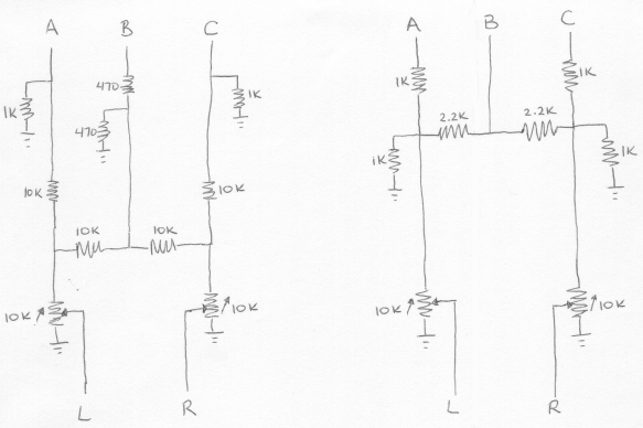
On the right is the “Polish circuit” I mentioned in my last post, with a 10K stereo audio potentiometer added at the output. On the left is a circuit I found on a ZX Spectrum hacking site, also with an output potentiometer. Neither circuit included a potentiometer originally.
You can probably see where this is going: the functions of mixing and attenuation conflict. Mixing works because the total resistance between A, B, or C and L or R is different for different paths. In the case of the Polish circuit (right side), if the potentiometer is turned all the way so there’s zero resistance between input and output, then the total resistance from A to L is 1K, from B to L is 2.2K, and from C to L is 5.4K. There more than 5x the resistance for C to L versus A to L, so A appears mostly on the left channel, and very little of C appears on the left channel.
If the potentiometer is now turned almost to the other extreme, so there’s 9K resistance between input and output, the situation changes. Now there the total resistance from A to L is 10K, from B to L is 11.2K, and from C to L is 14.4K. These are all similar enough that all voices go to both channels more-or-less equally, and the stereo effect is lost. This is where I’m stuck: I can get stereo mixing, or volume attenuation, but not both at the same time. The circuit on the left uses larger resistors, so the loss of stereo is less pronounced, but the maximum volume level is quieter.
Some ideas for addressing this problem:
- Move the potentiometer to after the headphone jack. This would allow for volume control of the amplified speaker, which is mono anyway, but the headphone jack would always be at maximum volume. In practice this would make the jack only useful as a line-out, and not for headphones.
- Change the stereo mix so that A and B go to the left channel, and C to the right, with no common path between them. This is simple but non-symmetrical, and the 100% stereo separation may not sound very pleasing.
- Use a transistor or op-amp as a voltage follower, inserted before the potentiometer, so that changes in the potentiometer resistance don’t affect the resistor network used for stereo mixing. This might be the best solution, but I’m uncertain how to build it, and don’t want to add still more elements to an already large circuit.
- Buy a second AY-3-8913, and create a six-channel audio system with three voices on each channel. Ha ha.
Progress on Audio
I’ve made some good progress on the audio hardware, working with the SN76489 and an Arduino microcontroller to help test things out. I put those components plus a clock generator on a breadboard, and wrote some simple Arduino programs to exercise the SN76489’s inputs. It didn’t take too long to get some simple tones, but I expect it will take much longer to learn to use the sound generator creatively to get the best possible results. Here’s a video of my contraption playing a continuous chord with one of the three voices ascending and descending:
I’m still not really sure what the “correct” way to connect this part to an external speaker is, but here’s the schematic showing what I did: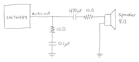
The first 10 Ohm resistor and 0.1 uF capacitor are there because they were in the datasheet for the related SN76494, to “prevent oscillation”. Whether they’re present or not doesn’t actually seem to make any difference, on the scope or to my ear. The 470 uF capacitor is there to remove the DC bias from the SN76489’s output, which swings back and forth around an average of roughly 3 volts. Without it, the circuit still works, but the sound isn’t as loud. The value of 470 uF was pure chance: I tried some smaller values around 1 uF, but they messed up the audio waveform. 470 uF was the next smallest value I had, and it worked. I’m not sure the second 10 Ohm resistor is necessary at all. I was trying to add some resistance to help prevent the total current draw from the SN76489 output pin from exceeding 10 mA, but I don’t think I succeeded.
With a single voice at maximum volume, and no speaker connected, the peak-to-peak voltage swing at the output pin is about 560 mV. With all three tonal voices at maximum volume, the swing is about 2 volts. The measured voltage drops by about half when the speaker is connected. Subjectively, the volume from the speaker is only medium-soft.
This all looks pretty promising, but despite that, I think I’m going to dump the SN76489 and put in the extra effort to try to get the AY-3-8913 working instead. While they’re generally similar, the AY-3-891x chip is enough more advanced that it sounds a lot better, at least to my ears. It’s in stereo, it’s got hardware envelope control, tonal voices can have noise in them, and there are two more bits of precision on the tone frequency settings. The SN76489 kind of makes me want to claw my eyes out after five minutes. Listen to this SN76489 music sample, and compare it to this AY-3-8910 sample, and you’ll see what I mean.
Read 18 comments and join the conversationAudio Plans
 It’s finally time to create an audio system for BMOW. There’s not much board space left, so this will likely be the end of the road as far as new hardware goes, save perhaps one or two miscellaneous chips. I’ve got space remaining for one more 0.6 inch DIP, or about six more 0.3 inch DIPs, depending on their pin counts. There’s also a spot where I’d planned to add a second SRAM, which is all wired up, but with some work it could be unwired to provide space for a second 0.6 inch DIP or two more 0.3 inch ones. This will be as much an exercise in space conservation as in hardware design.
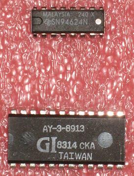
I bought two 1980s-vintage programmable sound generators from www.arcadecomponents.com: an AY-3-8913 and an SN76489. The BMOW audio system will include one of these, with a minimal amount of extra hardware to support it.
SN76489
This chip was made by Texas Instruments, and was also known as the SN94624 as seen in the photo. It was the sound engine in systems like the TI-99/4, IBM PCjr, Tandy 1000, Acorn BBC Micro, ColecoVision, and Sega Master System, and first went into production in 1980. It has three tone generators and one noise generator. The tone generators create simple square waves at programmable frequencies and amplitudes. The tone frequencies have 10 bits of precision. Altering the envelope for a sound requires the CPU to rapidly change the amplitude for a tone generator.
The chip itself is pretty small: a 16-pin 0.3 inch DIP. The four voices are mixed internally and connected to an analog sound out pin. Interfacing with the chip looks pretty simple: it’s like a slow RAM, with standard chip enable and write enable inputs. It is write-only, and cannot be read. The only complication is that writes take 32 clock cycles to complete, requiring some extra hardware to latch the data and CPU control signals and hold them for 32 clocks.
AY-3-8913
The AY-3-8913 is a variant of the AY-3-8910, which was used in systems such as the Atari ST, Amstrad CPC, Sinclair ZX Spectrum, Intellivision, and Vectrex. It was also at the heart of the Mockingboard sound card for the Apple II family. It is similar to the SN76489, but a bit more capable. The AY has three voices, each of which can be mixed from one of three independent tone generators and a single noise generator. The tone frequencies have 12 bits of precision. The tones are simple square waves, which are then modified by a hardware envelope generator to create triangle waves, sawtooth waves, and other patterns.
The chip itself is a 24-pin 0.6″ DIP. There are quite a few useless pins, so minimizing size doesn’t appear to have been a design goal. The three voices are connected to three separate analog sound out pins, so some extra hardware is needed to mix them for a single speaker. Presumably this is some kind of op-amp circuit, but I need to research it. Interfacing with the chip requires mimicking the two-wire bus protocol for some long-dead General Instrument CPU. It can be read or written. The timing requirements for setup, write pulse width, and hold times are slow enough that some extra interface hardware would be needed, probably similar to that for the SN76489, maybe a bit more complicated.
Pros and Cons
The TI chip requires less board space, and looks a bit simpler to interface with. It has a single-pin, pre-mixed output. It might still require an op-amp anyway in order to drive a speaker, though. The AY chip has a hardware envelope generator, and better precision for the tone generator frequencies. It definitely requires an op-amp to mix the channels and drive a speaker.
I should really design it out in detail, but I’m guessing the interface hardware for the AY would require two or three extra chips. Because it’s a 0.6 inch DIP, and the way the remaining BMOW board space is organized, it would require a bunch of long wires (about eight inches) spanning the width of the board. In contrast, I think I could do the TI SN76489 hardware with a single extra chip, and fit it all in one area of the board.
The bottom line looks like the TI chip will yield somewhat poorer audio results, but will be simpler to get going. I’m leaning towards it for that reason. I still need to do some more research into the AY interface requirements, and figure out how to sum channels and drive a speaker with an op-amp, then I should be ready to make a decision and get started.
Read 6 comments and join the conversationFun With Fonts
The BMOW display circuitry supports bitmap fonts, with each character on an 8×16 pixel grid. When I first built the hardware, I used an 8×16 font from X-Windows, but I never cared for it much. Here’s what it looks like:
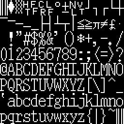 It’s a serif font, more at home on a printed document than on a computer screen. Notice how lower-case hij all run together, as do klmn, #$, and other font glyphs. Zero is taller than the other numbers. The period/decimal point is in the left portion of the glyph cell instead of centered, which looks very odd for a fixed-width font when it’s used as a decimal point. All the character strokes are one pixel wide, giving it a narrow feel. There’s one pixel of empty space between most characters, horizontally and vertically, so it also feels a bit crowded.
I decided to try some new fonts to replace the X-Windows one, but 8×16 fonts aren’t common. Instead, I tinkered with some classic computer fonts.
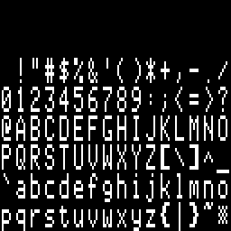 This is a slightly modified version of the character font from the Apple II series of computers. The Apple II font glyphs are 7×8, so I inserted an extra empty column into each glyph, and scaled it up to twice the original number of rows vertically, to get 8×16 glyphs. Like the X-Windows font, all the character strokes are one pixel wide, giving it that same narrow feel. The characters themselves are also pretty narrow, with most being only 5 pixels wide, providing 3 pixels of space horizontally between adjacent characters. Most characters are 7 pixels tall (14 after scaling), leaving 1 pixel (2 after scaling) of space vertically between adjacent characters. A lower-case letter with a descender will actually touch a capital letter on the line below it. I burned this into BMOW’s character ROM and played with it for a bit, but it just didn’t look right.
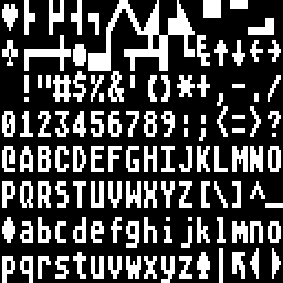 Ah, this is more like it. This is the 8×8 font from the Atari 8-bit computers, scaled up to twice the height vertically, to get 8×16 glyphs. It’s big and bold, with all the character strokes two pixels wide. The characters themselves are wider too, with most of them being six pixels wide, providing two pixels of space horizontally between adjacent characters. Most characters are actually shorter than the Apple II ones, though: 6 pixels high (12 after scaling), leaving 2 pixels (4 after scaling) of space vertically between adjacent characters. I burned this into BMOW’s character ROM, and was fairly happy with the results. My only real regret was that by scaling up an 8×8 font to make an 8×16 font, I was effectively throwing away half of BMOW’s vertical resolution.
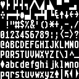 My solution was to retouch the Atari font by hand, taking advantage of the addition vertical resolution compared to the original to make curved edges look smoother. You can see the result here. In the process of smoothing the letters, I actually made them slightly bolder than they were before, so now this is an extra-bold in-your-face style font. I’m pretty happy with it overall, as it’s nice and legible, and has a good retro-8-bit style to it.
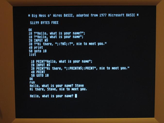
Here’s a photo of BMOW running MSBASIC with the final font: