Archive for the 'BMOW 1' Category
Memory Map
Recently I’ve been working on a revamped bootloader, turning it into a menu of cool built-in demos as well as its original purpose of downloading new programs from a remote PC. That’s led to some interesting tidbits, such as making the bootloader able to bootload itself. However, the biggest change to fall out of all this is a new memory map for BMOW.
You might be thinking that now is a strange time to consider rewriting the memory map, when the hardware is done and the machine is essentially finished, and you’d be right. Fortunately all of the relevant address decoding logic is contained in a single programmable GAL, and the memory and devices are connected to the address bus in a way that allows them to be located more-or-less anywhere in the address space, subject to some alignment requirements. The bulk of the work would be updating all the software I’ve written to work with a new memory mapping.
But why would I even consider a change like this? In the beginning, BMOW was conceived with a 16-bit address space, allowing for 64K of addressable memory:
| Range | Size | Contents |
|---|---|---|
| $0000 – $3EFF | 15.75K | ROM |
| $3F00 – $3FFF | 256 bytes | memory-mapped devices |
| $4000 – $FFFF | 48K | RAM |
Pretty simple. But at the last minute before I began hardware construction, I decided to expand the address space to 24 bits, allowing for 16MB of addressable memory. I added a third byte to the address bus called the bank byte, along with the existing low and high bytes. The instruction set was left mostly unchanged, however, so most instructions use 16-bit addresses, and implicitly reference the current bank. Thus the address space was divided into 256 banks of 64K each, and program references to different banks are fairly awkward (think x86 segment registers, etc). I left the first 64K bank mapped as it was originally planned, but added more RAM and eventually video RAM elsewhere in the address space. As a result, the current BMOW memory map looks like this:
| Range | Size | Contents |
|---|---|---|
| $000000 – $003EFF | 15.75K | ROM |
| $003F00 – $003FFF | 256 bytes | memory-mapped devices |
| $004000 – $07FFFF | 496K | RAM |
| $080000 – $1FFFFF | unused | |
| $200000 – $207FFF | 32K | Video RAM |
| $208000 – $FFFFFF | unused |
A little odd, but it works. The problem I’m running into now with this memory mapping is that there’s only 16K of ROM. That’s not much space to fit a whole collection of cool built-in demos. Physically the ROM is actually 128K, so more space exists, it’s just not mapped anywhere into the address space. This is what ultimately motivated the change to the memory map that I’m contemplating now. I assembled a set of requirements and goals for the new memory map:
- $000000 must be ROM, because that’s where the CPU begins after a cold boot.
- The interrupt vector must be somewhere in the first three banks ($000000 – $02FFFF) or last two banks ($FE0000 – $FFFFFF), due to limitations on the constants I can generate in microcode, so some part of that range must be RAM.
- The interrupt vector should be kept at its current location ($00FFFE-$00FFFF) if possible, to avoid the need for microcode changes.
- ROM must be mapped to a 128K boundary.
- RAM must be mapped to a 512K boundary.
- ROM should ideally be mapped to a contiguous 128K address space, with no holes.
- RAM should ideally be mapped to a contiguous 512K address space, with none of it masked by ROM occupying the same space.
- Existing memory mappings should be changed as little as possible, to minimize the amount of software changes required.
A relatively logical mapping would have ROM at $000000 – $01FFFF, RAM at $F80000 – $FFFFFF, and devices somewhere like $020000 – $0200FF. However, I’d really like to avoid the microcode changes required if RAM is relocated, and I have some reason to suspect intermittent hardware glitches due to address bus signal noise if using bank $FF. Relocating RAM entirely from its current position would also require more software changes.
Instead, I’m planning to keep the existing mappings as they are, but add additional mappings for the same RAM and ROM at different address ranges, in order to meet the other requirements. So RAM and ROM will appear multiple times in the address space. This is a bit strange, and I may come to regret it, but I think it will solve my current problems with minimum impact. Essentially, ROM will be re-mapped to a currently unused address space in a contiguous 128K block, and RAM will be re-mapped to an unused contiguous 512K block. Existing microcode and hardware will continue to work as-is, but new software can take advantage of the new mappings to access additional ROM and previously-hidden RAM. The new memory mapping will look like this:
| Range | Size | Contents |
|---|---|---|
| $000000 – $003EFF | 15.75K | ROM |
| $003F00 – $003FFF | 256 bytes | memory-mapped devices |
| $004000 – $07FFFF | 496K | RAM |
| $080000 – $0FFFFF | 512K | mirror of RAM |
| $100000 – $11FFFF | 128K | mirror of ROM |
| $120000 – $1FFFFF | unused | |
| $200000 – $207FFF | 32K | Video RAM |
| $208000 – $FFFFFF | unused |
On a side note, the BMOW site has been receiving dramatically more visitors in the past week, after it was picked up on Hack-a-Day and Reddit. Hello to the new readers!
Read 3 comments and join the conversationFinal Touches
Today I installed the front panel LCD, and hooked up the all-important power light. Fitting the front panel LCD was a major pain in the ass, especially after the death of my Dremel. I cut a hole in the front panel using a pair of tin snips, but it came out looking pretty ragged. Oh well, it’s functional. I had to ditch my faithful 20×4 LCD that’s been with me practically since day one, since it was too tall to fit, and substituted a 24×2 LCD in its place. As you can see in the photo, it works fine, but will require an update to my LCD driver to make text word-wrap correctly.
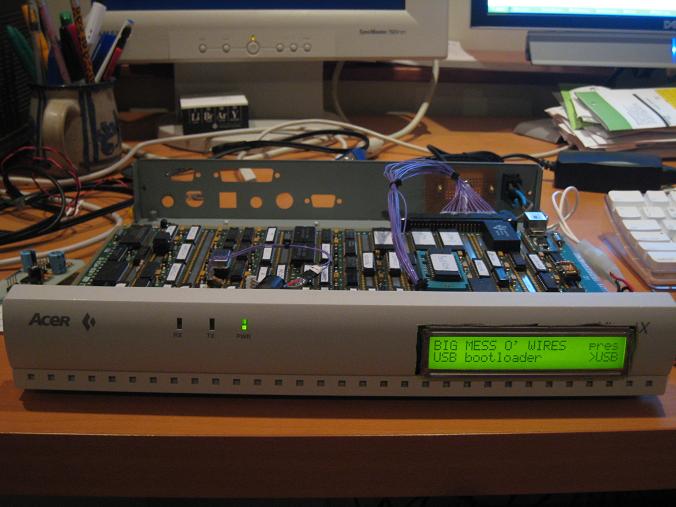
Barring anything unforseen, that’s it for BMOW hardware. I’ll be packing away the soldering iron and wire-wrap tools now, and concentrating on the software end of things for a while.
Read 1 comment and join the conversationFinishing the Case
The deed is done! Or at least the major parts of it. BMOW now exists as a sturdy pizza box enclosure, with real power and peripheral connectors that can stand up to repeated plugging and unplugging. It’s quite a step up from the bare circuit board with wires dangling everywhere that’s graced my desk for so long. In short, it looks like a real computer now!
A week ago, I wrote here about my adventures fitting the main circuit board into the case. With that done, I still needed to build the power connector, finish the audio daughter board, and create the rear port connector panel. This required a large amount of boring soldering and gluing, plus a bit of interesting design on the audio board. I’d never attempted to build a circuit on a generic PCB panel using soldered wires before, and it didn’t go too well. There must be a trick to neatly soldering up the required connections on the back side, but I didn’t find it. The back of the audio board is a mess, and required a few hours of debugging to find the flaky solder joints, but it all worked fine in the end.
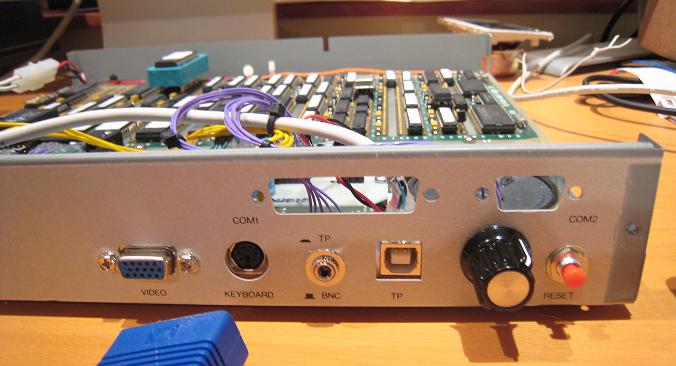
Here’s the rear of the case after installation of the DC power jack (in the space where the AC plug was originally), the VGA video connector, and the new reset button:
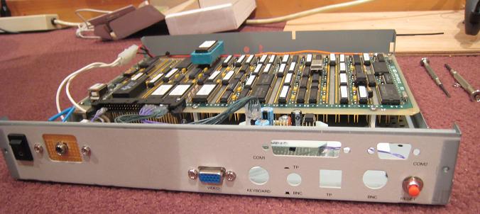
And here’s a top view of the same thing, showing the audio board installed, but no other components yet:
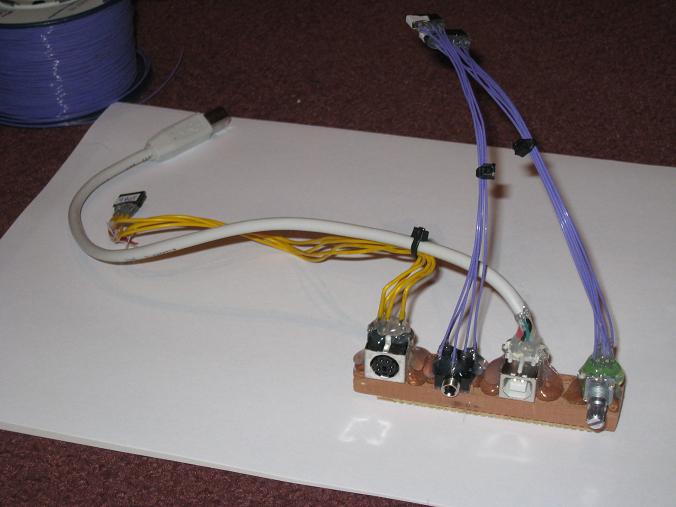
The hardest part was the rear port connectors. The headphone jack and volume knob are panel-mount connectors, but the keyboard and USB connectors are PCB-mount, and I didn’t have a PCB to mount them on. I need something to attach all the connectors to, to hold them in the right position relative to the holes in the case, and keep them sturdy enough to withstand the force of repeated pluggings and unpluggings. I ended up mounting the connectors on a piece of wood that was just the right height. The PCB-mount connectors were mounted upside-down on the wood, with the legs facing upward. That means the keyboard and USB connectors are upside-down, relative to how you’d see them on a normal PC. Odd, but not really a problem.
Here’s the finished rear port connector module. From left to right, it’s keyboard, headphone/line, USB, and volume. The connectors all run internally to jacks on the BMOW main board or audio board.
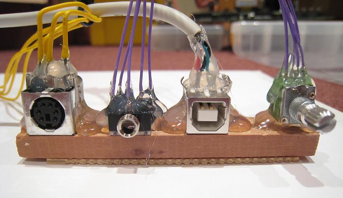
Here’s a close-up of the rear port connector module. There’s lots of hot glue poured over everything:
With everything crammed inside the case, including a small speaker, it’s a tight fit:
With the rear panel ports populated, it begins to look like a recognizable computer. I even found a retro-style volume knob. Who really cares if the USB port is actually labeled “TP”? Those vacant COM1/COM2 ports don’t look very nice, though. Ventillation holes?
At this point, I tried to put the cover on, and discovered that it didn’t fit! What the $@#*&#? I had to get out the Dremel tool once more, to grind down a small metal fin that projects from the inside of the cover down into the case. After grinding it off, there’s only about 0.1 inch of clearance.
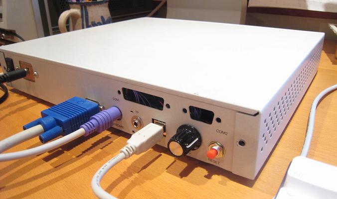
The finished product, with cover successfully installed:
Front view. I need to silkscreen a BMOW logo on there somehow:
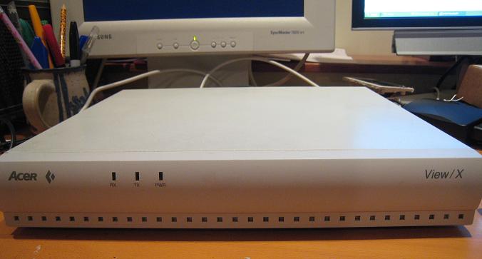
All this, and it still runs too:
That’s almost it for my hardware plans. I’d like to hook up those three LEDs on the front panel, and I’m probably going to cut an opening in the front to mount a 2-line LCD. Then I plan to tidy up the software a bit, and create a “demo ROM” with a menu of my greatest hits like animating kid photos, Microchess, BASIC, and music players. Then BMOW should be ready for its world tour, or a quiet retirement.
Read 8 comments and join the conversationBuilding the Case
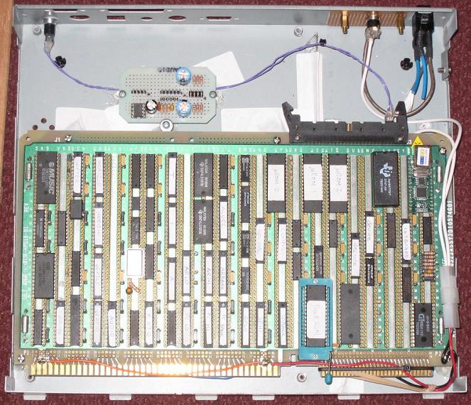
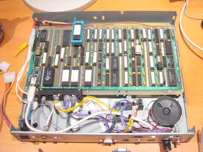
I’m making progress on building BMOW’s case. After more than a year of sitting naked on my desk, it’s finally going to get a proper enclosure: a gutted X-terminal that is just the perfect size… or so I thought. A couple of weeks I ago, I used a Dremel to cut out a divider that partitioned the interior space. Then this past weekend I did the first test-fit. Uh-oh! While the BMOW board did just barely fit inside, the lid wouldn’t fit on with the board in the enclosure. It was actually both too wide and too tall, by just a fraction of an inch in both dimensions. Doh! Here’s what the test fit looked like:
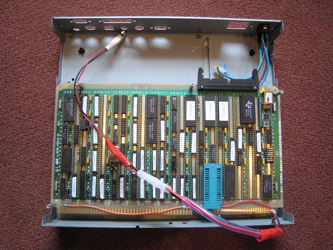
The lid (not shown here) has small tabs that extend into the case, and fit into grooves in the base. These tabs were bumping into the BMOW board when I attempted to close the lid. That’s not surprising, since you can see in the photo that there’s virtually zero extra space horizontally. In fact there’s about 1/16 inch of space to spare on both sides, so I cut the tabs down to that size with the Dremel, and now they just barely squeak through.
I wasn’t out of the woods yet, though. The lid still wouldn’t close, because the board was just a fraction of an inch too tall. Putting a ROM in that green ZIF socket you see in the photo was just barely enough to prevent the lid from closing. After some thought, I decided to solve that problem by using shorter standoffs underneath the board, so it would sit lower in the case. That was easier said then done, however, because the wire-wrap pins on the bottom are about 3/4 of an inch long, so the standoffs need to be taller than that. I found some standoffs that worked, but now those pins came so close to the bottom of the case, that they actually made contact with the jagged remnants of that divider I’d previously removed. I had to go back and grind the divider down to a nub with the Dremel before it all fit.
The next problem I faced was how to anchor the board securely in the case. Drilling mounting holes for the standoffs would work, but I don’t have any way of measuring and drilling the holes accurately enough to match the holes in the board. In the end, I decided to screw the standoffs into the board, then stick the whole thing in the case and hot glue the standoffs to the case’s base. This had “bad idea” written all over it: there was a decent chance I might accidentally melt or glue the the board itself while anchoring the standoffs. That was risky enough, but it gets worse. You can see in the photo that I had good access to the top and side of the board with the glue gun, I couldn’t really reach the bottom side. Unfortunately BMOW has only two mounting holes on the bottom side: bottom-left and bottom-middle (hidden under the cable in the photo). I actually dragged the whole thing down into the basement, and drilled a new mounting hole in the bottom-right of the PCB with everything still mounted on it, and the whole thing in the case. It was a little comical. I covered all but that corner with a towel to protect it from flying metal flakes off the drill, but one mistake could have easily destroyed a year’s work.
Fortunately the surgery went without a hitch, and I got the board nicely mounted in the case. I also ditched the jury-rigged power cable you see in the photo that has caused me so many headaches, and carefully wired up new power connections, this time with a real power switch too! With the new connections, I measure 4.96 volts on the board, instead of the 4.75 or so I used to see with the old hookup.
The hardest part of this job is hopefully behind me now, but there’s still a lot of work to do fashioning new connectors from the BMOW board to the case holes, and building a small off-board audio mixer/amplifier circuit. I need to build new VGA, keyboard, USB, volume, audio, and reset cables, solder them all to the appropriate connectors, and devise some way to mount them all neatly and securely aligned with the holes in the case. Earlier I’d considered building a small custom PCB for this, but I think I’ll probably just do it all by hand. I have a strong suspicion that hot glue will play a role once again!
Read 3 comments and join the conversationMusic Demo
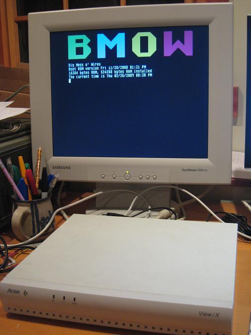
I’m very pleased to say that after a few false starts, and lots of slow plodding progress, I finally have an audio demo to show off! The AY-3-8913 and related interface circuitry have been integrated into BMOW, and it works flawlessly. I’ve routed the analog voltages for the three voices to an off-board mixer/amplifier circuit, which is currently on a protoboard. Then I grabbed some old chiptunes from an AY emulator, deciphered the basics of the emulator file format, and shoved the resulting raw register data into the AY at 50Hz. This is the result.
The video demos a three minute chiptune, which just barely squeezed into 64K. It also shows off my desk workspace. That’s the PC monitor on the right displaying the BMOW bootloader UI, and the BMOW system monitor on the left. Keep your eyes peeled for the logic analyzer, Arduinos, and some other goodies mentioned in long-ago BMOW posts too.
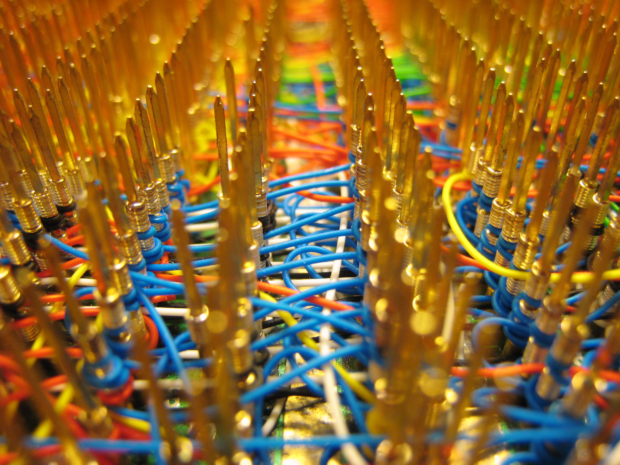
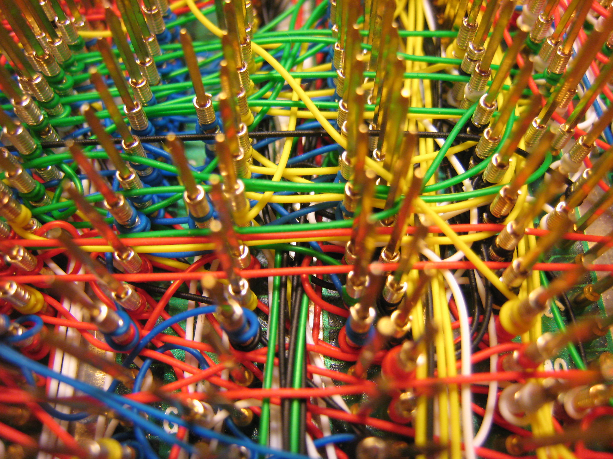
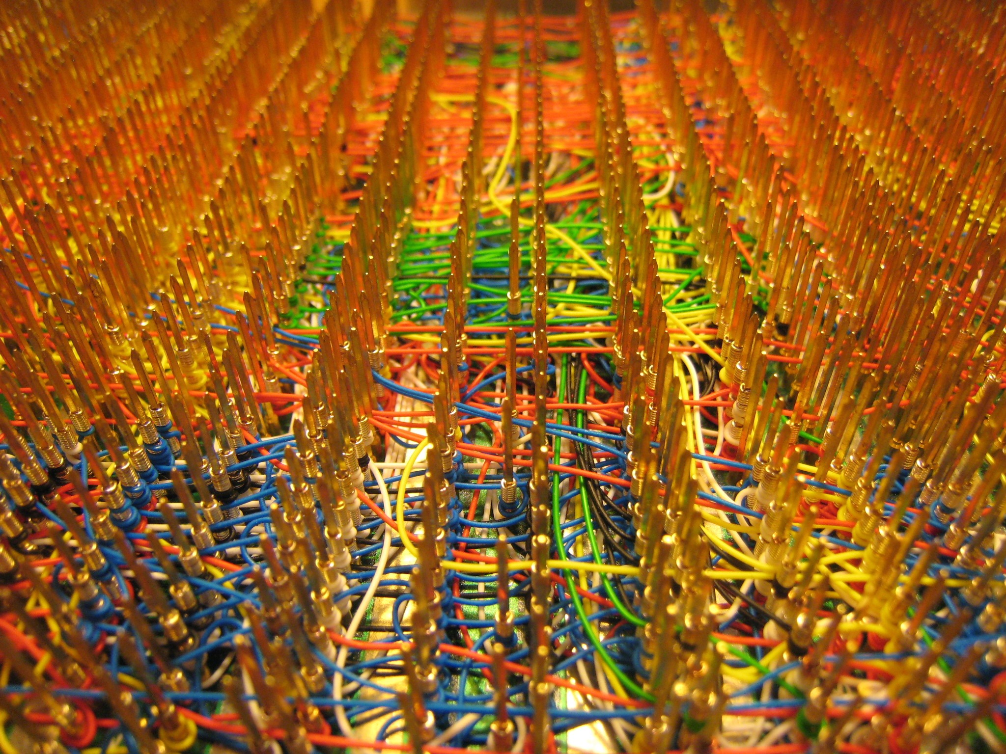
Read 3 comments and join the conversationWire-Wrap Photos
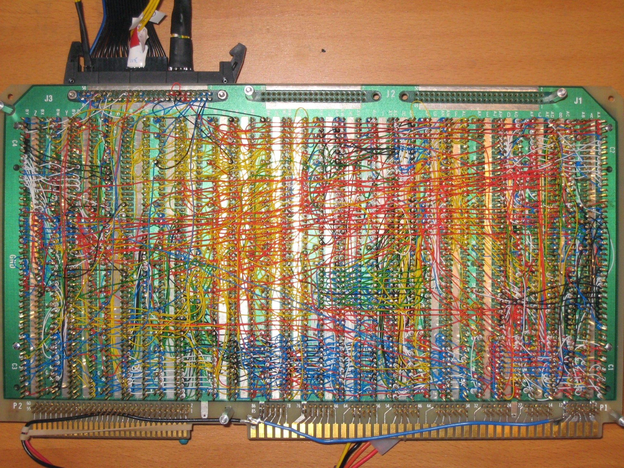
I finished wiring the audio circuitry for BMOW yesterday, which marks the end of wiring for BMOW… for version 1 at least! I took the opportunity to reflect on my wire-wrapping odyssey, and took a bazillion photos of the namesake Big Mess o’ Wires before it disappears forever into an opaque case. It’s really quite a sight. There are 1253 wires with 2506 individually-wrapped connections, and I’ve got every one logged in a spreadsheet.
At first I found the slow pace of wire-wrapping to be a chore, but eventually I came to enjoy it. Once I get going, I can wrap about 25 wires in an hour. It’s almost like a form of meditation. Despite how long it takes to wrap, the wire-wrapping hasn’t really impacted my overall rate of progress. Design, debugging, and general procrastination consume the most time, and wrapping is just a small part of the total.
All this craziness is built on a 12×7 inch Augat wire-wrap board with 2832 gold wire-wrap posts, which I purchased from eBay for $50. I started wondering about all that gold… are those posts solid gold, or gold-plated? I broke one once, and its cross-section appears to be solid gold. I know the boards sold for astronomical prices when new, and the name Augat suggests the atomic symbol for gold. The board was even listed in the precious metals section of eBay, rather than anywhere electronics-related. With a postage scale and a little figuring, I estimated the total weight of all the pins at about 10 ounces. Assuming it’s solid 10 karat gold, that’s 4.1 ounces of pure gold, with a value of about $3700 at today’s gold price. Too good to be true?
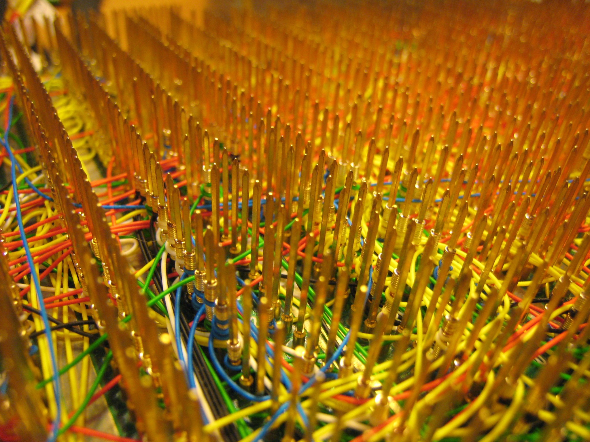
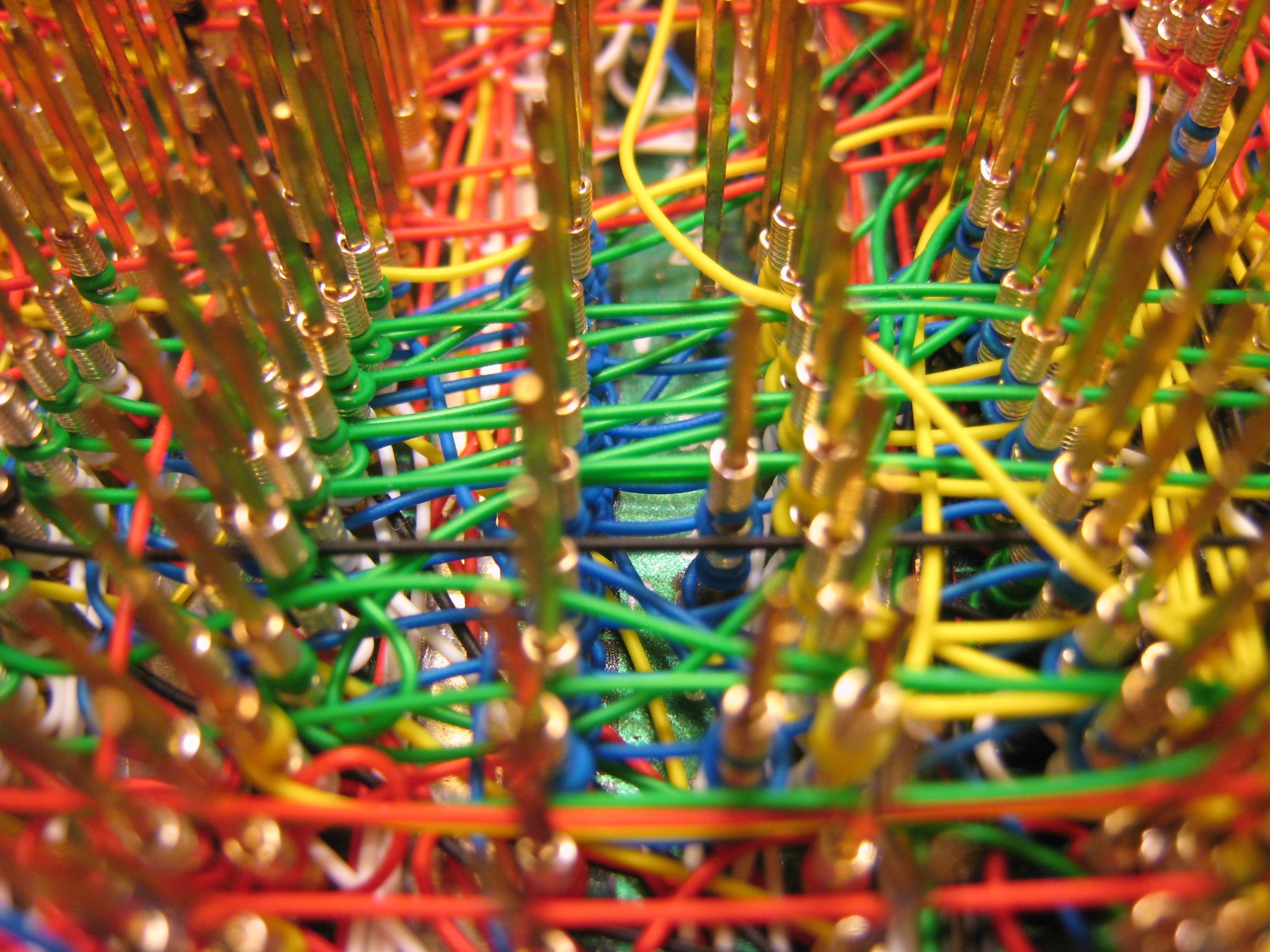
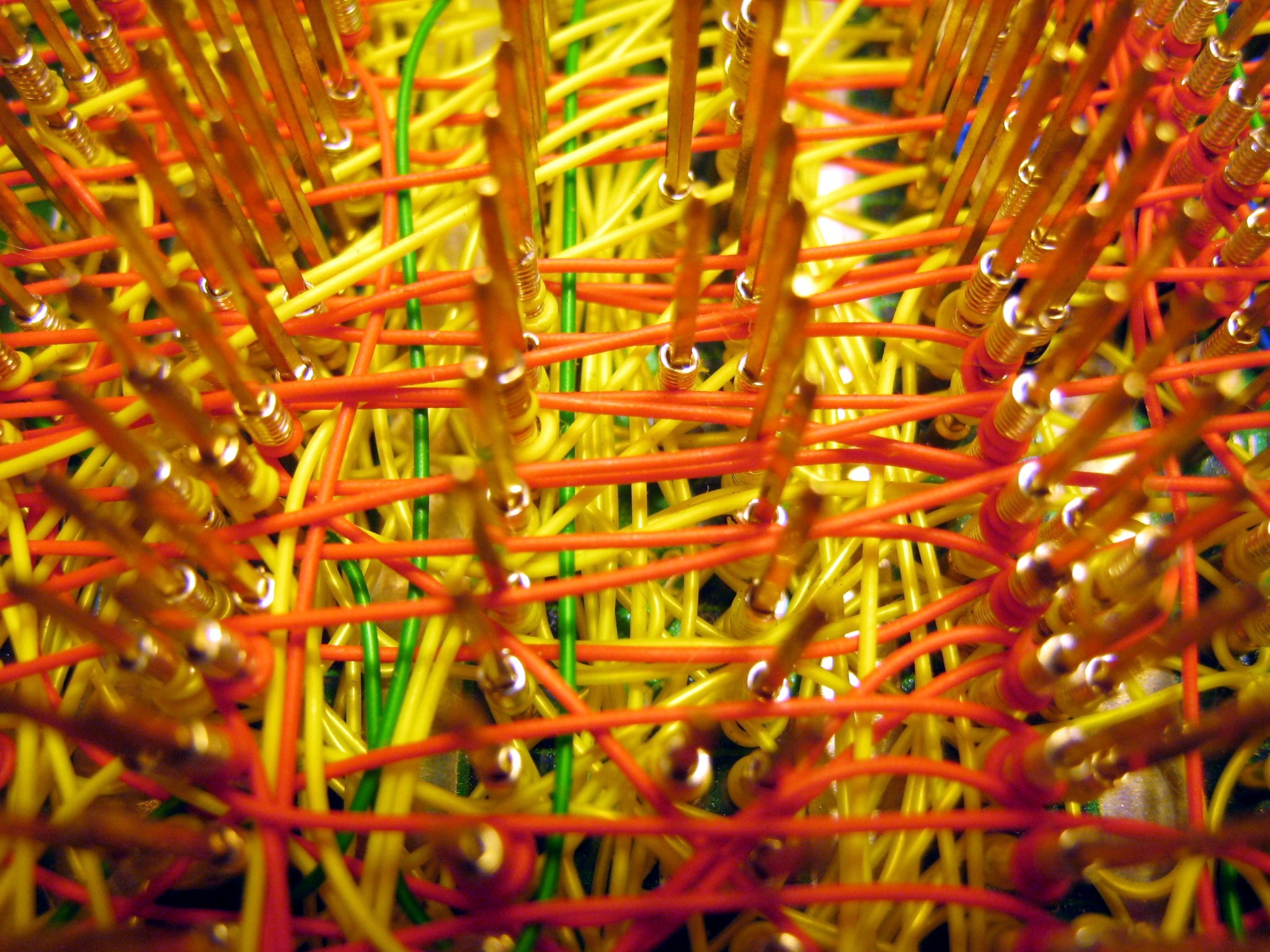
In the photos, I tried to capture the feeling of order amid chaos. Click any image to see the full-size version. What I found remarkable is just how dense the wiring is in many parts. The wide shots show off the surface wiring, but the close-ups really get into some interesting rats’ nests. In the densest channels, those wires are stacked at least 10 deep! It’s hard to believe it actually implements a computer.
Behold the insanity that is Big Mess o’ Wires!