

Mysteries of Macintosh High Density MFM Disks
In the classic Macintosh world, 400K and 800K floppy disks use GCR encoding but 1440K disks use MFM encoding. The BMOW Floppy Emu disk emulator has supported 1440K MFM disk emulation for years, and I thought I knew everything about how it worked. Recently I dug into Mac MFM again, while adding support for in-emulator formatting of disk images, and discovered some bad assumptions as well as some critical but undocumented behaviors of the Macintosh-Sony high-density floppy drive – or at least behaviors not documented anywhere that I can see.
I’ll gloss over most of the errors and misunderstandings in my MFM design, but there were many of them. One of the biggest was using the wrong sync byte value in some places: $AA instead of $4E. Fixing this was surprisingly difficult, due to a design practice of repeating a single $A nibble value to create the $AA sync byte, which wouldn’t work for $4E.
Index Pulses
The most interesting discoveries were related to how the Mac-Sony HD floppy drive handles index pulses. Yes that’s right, index pulses. If you’re like me, you may have thought that Macintosh floppy disks are all soft-sectored and don’t use index holes. That’s true, the disks don’t have any hard indexing mechanism, but the high density drive does. For every rotation of the disk, the drive’s index signal pulses briefly high.
But where and how can the computer read this index signal? Some readers may know that 3.5 inch Sony floppy drives have 16 internal 1-bit state registers, whose values can be read by the computer by selecting a register using the CA2, CA1, CA0, and SELECT I/O signals. This table is from Inside Macintosh Volume III:
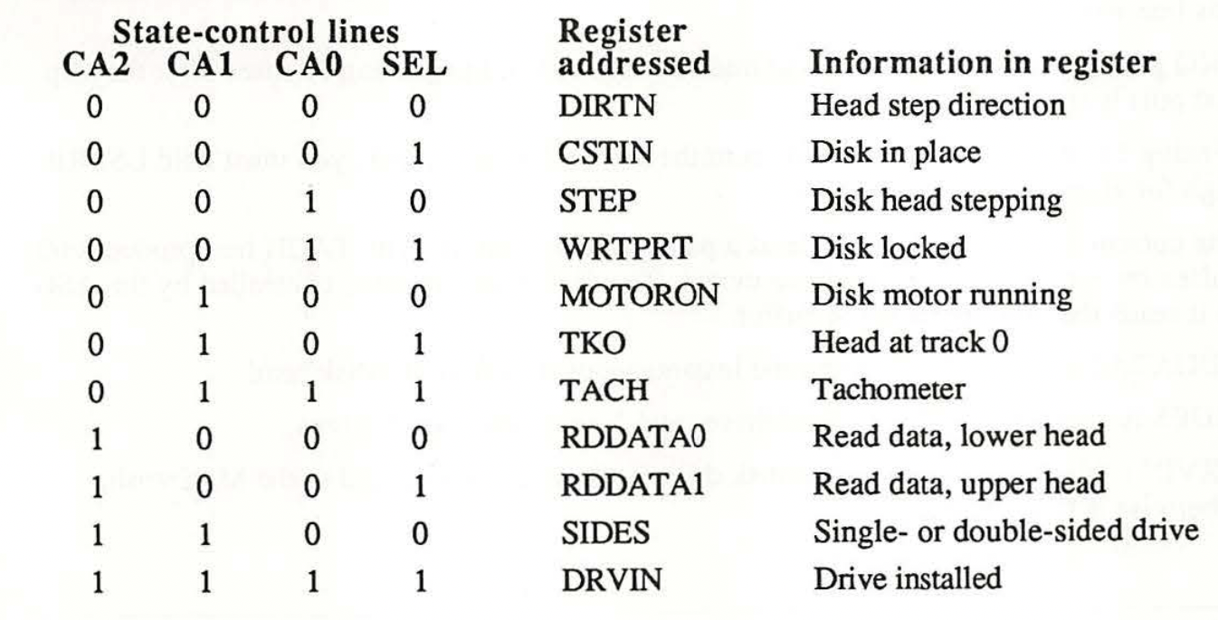
You’ll find very similar tables in a few other sources, like the IWM documentation for Linux on Mac 68000. The Floppy Emu’s 3.5 inch drive emulation is built around this table – it emulates these registers. There are registers for things like motor on, write protection, and step direction… but I don’t see anything about index pulses.
Well, it turns out that this table is only valid for 400K and 800K floppy drives, but I’ll be damned if I can find a good source that documents the differences for other types of drives. Based on some old cryptic notes, and a logic analyzer trace of the disk I/O signals while a Macintosh LC formats a real 1440K floppy, I was able to conclude that the 0111 TACH register is actually an INDEX register for 3.5 inch high density Sony drives operating in HD MFM mode. I think I may have seen documentation of this somewhere in the past, but can’t locate it now. Floppy Emu doesn’t emulate this INDEX behavior at all, and it’s not needed when reading or writing a disk, but it turns out that it’s crucial when formatting a disk.
Reading While Writing
While examining the logic analyzer trace from the Macintosh LC as it was formatting a disk, I noticed something else curious. The computer sometimes asserted the write-enable signal for much longer than a single rotation of the disk, which is all that should be needed for a single track. Sometimes it was almost two rotations of the disk. I also noticed an odd pattern reading the RDDATA0 and RDDATA1 registers while writing to the disk. What should the read data even be, in the middle of a write operation? I’d never thought about it before, and don’t know of any software that might attempt to do it. But I noticed there was always a single 0 to 1 transition on RDDATA somewhere in the middle of the write, occurring at different times after the start of the write for each track, but always appearing about 200 ms before the end of writing.
For a very long time, I simply wrote this off as an unimportant detail, but eventually I realized that the step transition on RDDATA while writing is the INDEX pulse. I’ve never seen this behavior documented anywhere, but after reviewing the logic analyzer trace it was undeniable. The computer begins to format a track by writing a continuous string of sync bytes, while simultaneously reading RDDATA0 or RDDATA1. When it sees a low to high transition there, it knows it’s the index pulse, and it begins writing the first sector beginning just after that spot. From there it continues to write all the other sectors, ending the write operation just before the index pulse is due to appear again. Finally it checks the index pulse again, this time by reading the INDEX register the normal way at 0111. If everything checks out OK, then it steps to the next track and repeats the process.
This was my ah-ha moment, when all the pieces suddenly clicked into place and I could understand why the computer was responding differently to the Floppy Emu during formatting than it did to a real drive. Now I need to make additional firmware modifications, and try to get Floppy Emu to emulate this same behavior.
Read 1 comment and join the conversation1 Comment so far
Leave a reply. For customer support issues, please use the Customer Support link instead of writing comments.
The System 7.1 source code leak has the source for the Sony drivers and SonyMFM.a has a routine mDoFormat with the checks for bit 3 of handshake register looking for Index pulse. Archive.org also has some information on IWM/SWIM versions https://archive.org/details/SWIMDesignDocs.