

BMOW 1 Computer

Back in early 1980’s, I lived and breathed the world of the Apple II, Atari 800, Commodore 64, and their brethren. I could PEEK and POKE those machines like nobody’s business, and I spent countless hours writing programs, playing games, or just fiddling around. In contrast to today’s PCs, the computers of that era were inviting to tinkerers, with a comparatively simple hardware design and a BASIC prompt at boot-up.
As a computer engineering major in college, I learned the details of digital logic design. I even built a rudimentary computer on a prototyping kit built into a suitcase: MIT’s infamous “Nerd Kit”. But at the end of the semester, it was all torn down, I went on to a career in software, and that was that.
More recently, I learned of various projects to build simple computers similar to those 80’s machines, constructed entirely of discrete logic chips like counters, adders, flip-flops, and NOR gates. No Pentiums or PowerPCs here– these people built their own CPUs from the ground up, along with the memory subsystem, I/O, and everything else the computer required. I had stumbled onto the world of the homebrew CPU. To create such a computer required a detailed microarchitectural design, custom instruction set design, custom software tools like assemblers and compilers, and of course a custom circuit board or three populated with lots of fat DIP chips and a big mess o’ wires. Projects like the Magic-1, D16/M, and Mark 1 FORTH Computer showed me the way.
I decided to build a homebrew CPU computer of my own. It was a big mess o’ wires.
Construction is documented in 100 blog posts, ranging from the original idea through dozens of setbacks to a final demo for thousands of people at the 2009 Maker Faire.
The Hardware
Big Mess o’ Wires 1 is an original CPU design. It does not use any commercial CPU, but instead has a custom CPU constructed from dozens of simple logic chips. Around this foundation is built a full computer with support for a keyboard, sound, video, and external peripherals.
My original goals were:
- Build the CPU from scratch, primarily using basic 7400-series logic. No 6502, Z-80, etc.
- Keep the hardware complexity to a minimum. I’m not an electrical engineer.
- Be capable of running “real” programs, not a 4-bit CPU or toy machine.
- Provide a way to interface with a PC.
- Be fast enough to run interesting programs interactively.
Stretch goals:
- Boot into a simple integer BASIC program, capable of interactively editing and running its own programs.
- Support multiple programs executing simultaneously, via a pre-emptive multitasking OS.
- Provide keyboard input, VGA video and sound output.
Initial design began in November 2007 with a high-level sketch of the CPU internal design. A simplified Verilog hardware simulation proved the key design details. Construction began in earnest in February 2008, using a large wire-wrap board to interconnect the 50 or so chips needed. In April, a half-finished BMOW 1 booted up for the first time, computing fibonacci(12) = 144 using a simple ROM-based program. One by one the original system goals and stretch goals were met, including VGA video, three voice audio, BASIC, and a bootloader for communication with an attached PC. BMOW 1 eventually gained the ability to run complex programs written in assembly or compiled from C. The main construction phase ended in February 2009, with the completion of a customized case to house everything. As of March 2009, Big Mess o’ Wires 1 is fully functional, but will probably never be “finished”.
Architecture
BMOW 1 borrows liberally from other homebrew designs, as well as the MAYBE design presented in the book Computation Structures by Stephen Ward and Robert Halstead. Data busses are 8 bits wide, and the address bus is 24 bits. Four 8-bit registers are used for general data, and three 24-bit registers store the program counter, stack pointer, and a scratch/working address pointer. Registers and the arithmetic and logic unit are interconnected by one data bus, while RAM, ROM, and memory-mapped hardware devices use a second data bus. The ALU also has dedicated left and right data input busses.
Machine language instructions are implemented as a series of micro-instructions, stored in three parallel ROMs to create a 24-bit microcode word. One micro-instruction is executed each clock cycle, and the micro-instruction bits are used directly as enable and select inputs to control all the chips in the machine. Up to 16 micro-instructions may be needed to implement a single machine language instruction.

Note: Some additional devices are not shown here, including the VGA display circuitry and real-time clock.
24-bit addresses allow for up to 16MB of memory, but only a little more than 1MB of combined RAM and ROM is installed. The most-significant byte of the address is called the bank byte, and is normally invisible to programs. The standard instruction set presents a 16-bit interface to programs, with most instructions implicitly referencing the current bank. Cross-bank references are possible, but awkward (think x86 segment registers).
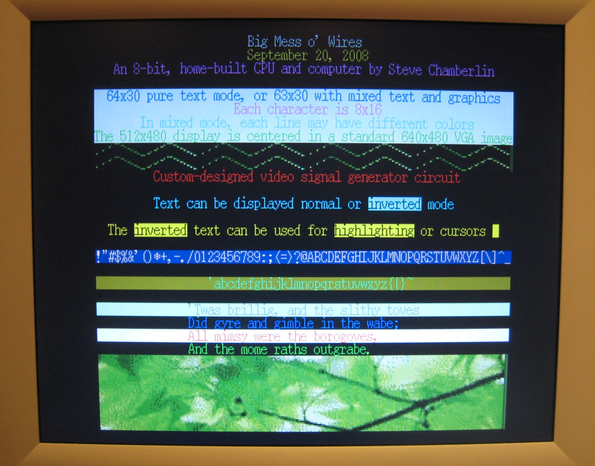
A 512K ROM contains a bootloader/menu program. A USB-to-TTL interface based on an FTDI chip provides an easy way to move data to and from a connected PC. A standard PC keyboard with PS/2 connector is used for keyboard input, and a 24×2 character text LCD serves as a debug output display. Custom video circuitry drives a standard VGA monitor, with a maximum resolution of 512 x 480. A three-voice programmable sound generator provides music and sounds.
BMOW 1 is built on an Augat wire-wrap board pre-populated with thousands of wire-wrap pins. The chips are pushed into the board without soldering, and can be easily removed, similar to a prototyping breadboard. Unlike a breadboard, the pins are individually connected on the underside of the board according to the needs of the circuit design. A wire-wrap tool is used to wrap stripped wire ends tightly around each pin. Wires can be removed fairly easily in case of a mistake. BMOW 1 contains about 2500 such wire wraps.
Specs
- Current clock speed is 2MHz. It could theoretically go to about 3MHz (untested).
- 512 KBytes of RAM, 512 KBytes of ROM.
- Power draw is 10 Watts, 2.0A at 5V.
- VGA video output is 512×480 with two colors, or 128×240 with 256 colors.
- Audio and music is provided by a three-voice programmable sound generator.
- Keyboard input is a standard PC keyboard with PS/2 connector.
- Debug display is a 24×2 character text LCD.
- There are roughly 1250 wires connecting the components, so 2500 individual hand-turned wire wraps.
Files
- BMOW Block Diagram – Shows the system busses and data paths for BMOW 1’s custom CPU.
- Video System Block Diagram – Shows the design of BMOW 1’s video display circuitry, the most complex subsystem in the machine.
- Layout – Shows the location of every chip on the BMOW 1 system board, color-coded by subsystem. More discussion of the layout is in the post Board Layout.
- Schematic Diagrams – The whole enchilada: detailed diagrams showing every chip, every pin, and every connection.
- Wire List – A spreadsheet documenting every wire in the machine, its endpoints, and the order the wires were added. Essential for navigating the insane rat’s nest of wiring beneath the board. (The spreadsheet has embedded macros. Excel may warn you about this.)
- GAL Programming Equations – Data on the various programmable logic elements used throughout BMOW 1.
- Microcode – Source listing for the microcode that implements BMOW 1’s high-level machine instructions. Each high-level (programmer visible) instruction is implemented as a tiny program of 1 to 16 micro-instructions. The high-level instruction set that’s implemented in this microcode is a close cousin to 6502 assembly language.
- Microcode Assembler – A PC-hosted tool that reads the microcode source listing, and generates the binary data to be programmed into the microcode ROMs. It’s a custom assembler for microcode.
- BMOW simulator (requires the Microsoft .NET Framework 2.0 runtime) – A PC-hosted GUI-based BMOW 1 hardware simulator. Load a ROM image, single step the simulated machine, set breakpoints, view callstacks, reference source code, and much more.
- PC Bootloader – A PC-hosted GUI tool for downloading a program to BMOW 1’s RAM and executing it.
- Program Assembler – A PC-hosted command-line tool for assembling BMOW 1 source code into executable programs. It’s a customized version of the Acme 6502 assembler, with BMOW 1-specific extensions.
- Software Examples – Source listings from BMOW 1 programs, including the bootloader client that runs on the BMOW 1 hardware, and audio/video demos.
- Prototype Verilog Description – A Verilog model for an early prototype of the BMOW 1 CPU core. This is badly out of date now, and there are a couple of places where I cheated and wrote non-synthesizable code, so you couldn’t make hardware directly from this. Mainly for historical interest.
- Modified Atari Font Map – The 128×128 pixel font map originally used for BMOW, taken from the Atari 8-bit computer. Each letter is 8×16, and there are 128 letters in the font map. The image shown here is actually 256×256 and must be reduced 50%. Also, the raw binary version of the font map, already reduced and with the PNG header stripped out.
- 8×16 Font Map – The 128×128 pixel font map used for the final version of BMOW, adapted from an X-Windows font. Each letter is 8×16, and there are 128 letters in the font map. The image shown here is actually 256×256 and must be reduced 50%. Also, the raw binary version of the font map, already reduced and with the PNG header stripped out.
- Microsoft BASIC for BMOW – Pagetable.com reverse-engineered this excellent, retargetable version of MSBASIC for many different 6502-based computers in 2008. I added BMOW as a new target, and it assembles using the modified ACME 6502 assembler above.




This is fantastic and makes me wish my Cosmac Elf still worked.
question im half way into 1 but it wasnt thought trough very well how do i hook this up
plz respond if not i guess ill have to make my own motherboard
how much power does bmow use per power on
cool! нечего сказать!
Wow, I have always wanted to do something like this. I have been wanting to make my own computer since I cracked open a windows 95 computer back in early 2000.
Huh CS in middle school, add another person to the list of people wishing that they had gone to that middle school.
Just wondering, is there a parts list for this? Also I have been wondering could this adapted for any past and present processor or just ALU and Z80? I would like to make something like this, just on a bigger board (now where did I put that contact for that company who sells wall sized circuit boards again? just joking!)
Now, if you could do it with 7400 series chips, you should be able to build the same CPU with reed relays!
Epic computer! I’m planning on building a 16 bit CPU heavily influenced by your system but I was wandering… What are all the functions the 74LS181 provide?
Oh, does it support multiplication because it doesn’t look like it in function tables
Multiplication is done in a software routine, same as it was on the old Apple II and similar 8-bit machines. It’s not fast, but it works. Check out the ‘181 datasheet for a full list of what it does, but it’s basically just addition, subtraction, AND, OR, XOR. A good example of a discrete CPU like BMOW but that’s 16-bit is http://www.timefracture.org/D16.html
Hi!
A few months ago I designed an 8-bit CPU from scratch. It was very basic. Currently I haven’t been able to build it yet, but it works beautifully on a simulator.
Tonight I found your BMOW project and I must say the mess of wires is truly inspirational! Your Nibbles project has also told me that I can probably build a CPU right here and now: without having to order the parts for my 8-bit design.
I saw in the comments: If you ever make a second one, twisting each line with a ground connected line is an effective means to reduce cross talk (make sure to minimize capacitance [by using fine gauge wire]).
My question is how fine of a wire do I need, since wire wrap is so thin already. I have some transformer wire that is as thin as human hair. Should I wrap it with several coils per unit distance or medium or just a few?
Thanks
Steve
Haha, I hate to tell you, but you are, in fact, an electrical engineer 🙂
Very nice!
The last time that I saw something this ambitious was in the 70’s. I had run into an EE who built me a memory board for my Mattel Aquarius computer. While picking it up at his house, he showed me his project (a homegrown CPU like yours).
Where did you get your wirewrap tools? I’m specifically looking for a wirewrap gun.
Thanks!
I actually didn’t use a wirewrap gun – everything was done with a wirewrap hand tool. You can still find some supplies at vendors like Phoenix Enterprises, but they’re definitely getting pretty rare. It’s a dying technique.
Sigh… I figured as much. I actually have two of them, but no bits for one of them. And a fairly respectable supply of sockets and wire. 🙂
Just not the patience to strip all of those wires. 🙂
Hello,
How is this possible?
*: A <- A + A; latchNZC; nextop
Latching flags must be done a half clock cycles after the ALU operation? Otherwise there should be timing issues or is there an independent ALU flag register somewhere in GALs?
Axel.
The new N, Z, and C flag values are generated at the same time as the ALU output. All are latched at the end of the clock cycle.
Hi, thanks for the info. How is this being done? I can’t see such a function in 181.
*: A <- A + A;
Axel.
Take a look at the 74LS181 datasheet. A + A is one of the 16 arithmetic functions it can calculate.
Yep, so it is. The datasheet I looked was a little bit misleading on that matter.
Axel.
Surprised that I found this so late. Coolest project ever
Hello, sorry for being very late. How do your computer handles interrupts? I have no idea on how that part works. Sorry for interrupting.