

BMOW Project Summary
Crazy day today! Maker Faire setup begins tomorrow, and BMOW is featured on wired.com, and is the #1 Top in All Topics story on Digg! Oh man, this poor server is getting hammered.
Many people have asked for high-res photos. See this entry from February, and click any of the thumbnails to get the high-res versions of wire-wrapping craziness.
For people interested in viewing or buying the “Making of BMOW” photo book, you can order it from Shutterfly here.
Here’s a summary of the project, for everyone following the link from the article.
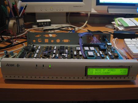
Big Mess o’ Wires 1 is an original CPU design. It does not use any commercial CPU, but instead has a custom CPU constructed from dozens of simple logic chips. Around this foundation is built a full computer with support for a keyboard, sound, video, and external peripherals.
My original goals were:
- Build the CPU from scratch, primarily using basic 7400-series logic. No 6502, Z-80, etc.
- Keep the hardware complexity to a minimum. I’m not an electrical engineer.
- Be capable of running “real” programs, not a 4-bit CPU or toy machine.
- Provide a way to interface with a PC.
- Be fast enough to run interesting programs interactively.
Stretch goals:
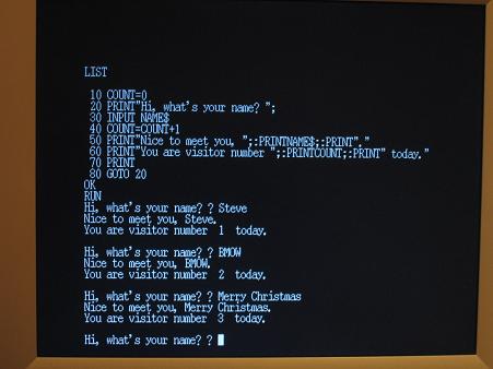
- Boot into a simple integer BASIC program, capable of interactively editing and running its own programs.
- Support multiple programs executing simultaneously, via a pre-emptive multitasking OS.
- Provide keyboard input, VGA video and sound output.
Initial design began in November 2007 with a high-level sketch of the CPU internal design. A simplified Verilog hardware simulation proved the key design details. Construction began in earnest in February 2008, using a large wire-wrap board to interconnect the 50 or so chips needed. In April, a half-finished BMOW 1 booted up for the first time, computing fibonacci(12) = 144 using a simple ROM-based program. One by one the original system goals and stretch goals were met, including VGA video, three voice audio, BASIC, and a bootloader for communication with an attached PC. BMOW 1 eventually gained the ability to run complex programs written in assembly or compiled from C. The main construction phase ended in February 2009, with the completion of a customized case to house everything. As of March 2009, Big Mess o’ Wires 1 is fully functional, but will probably never be “finished”.
Architecture
BMOW 1 borrows liberally from other homebrew designs, as well as the MAYBE design presented in the book Computation Structures by Stephen Ward and Robert Halstead. Data busses are 8 bits wide, and the address bus is 24 bits. Four 8-bit registers are used for general data, and three 24-bit registers store the program counter, stack pointer, and a scratch/working address pointer. Registers and the arithmetic and logic unit are interconnected by one data bus, while RAM, ROM, and memory-mapped hardware devices use a second data bus. The ALU also has dedicated left and right data input busses.
Machine language instructions are implemented as a series of micro-instructions, stored in three parallel ROMs to create a 24-bit microcode word. One micro-instruction is executed each clock cycle, and the micro-instruction bits are used directly as enable and select inputs to control all the chips in the machine. Up to 16 micro-instructions may be needed to implement a single machine language instruction.
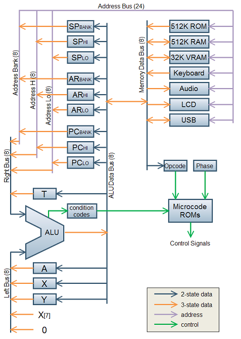
Note: Some additional devices are not shown here, including the VGA display circuitry and real-time clock.
24-bit addresses allow for up to 16MB of memory, but only a little more than 1MB of combined RAM and ROM is installed. The most-significant byte of the address is called the bank byte, and is normally invisible to programs. The standard instruction set presents a 16-bit interface to programs, with most instructions implicitly referencing the current bank. Cross-bank references are possible, but awkward (think x86 segment registers).
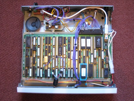
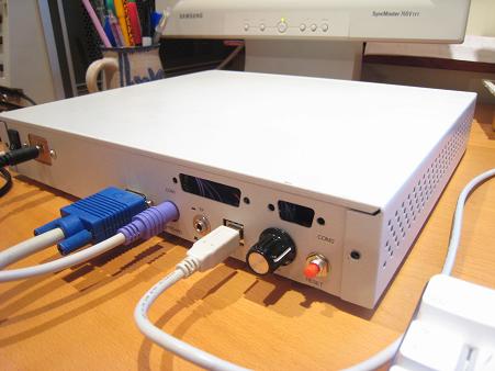
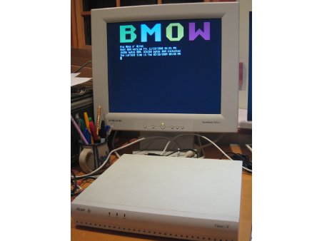
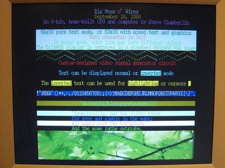
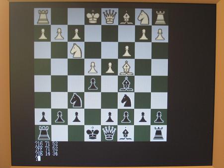
A 512K ROM contains a bootloader/menu program. A USB-to-TTL interface based on an FTDI chip provides an easy way to move data to and from a connected PC. A standard PC keyboard with PS/2 connector is used for keyboard input, and a 24×2 character text LCD serves as a debug output display. Custom video circuitry drives a standard VGA monitor, with a maximum resolution of 512 x 480. A three-voice programmable sound generator provides music and sounds.
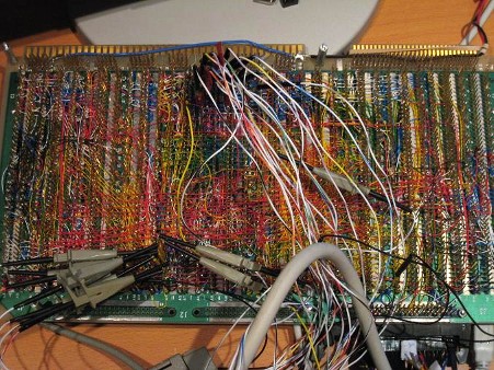
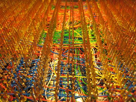
BMOW 1 is built on an Augat wire-wrap board pre-populated with thousands of wire-wrap pins. The chips are pushed into the board without soldering, and can be easily removed, similar to a prototyping breadboard. Unlike a breadboard, the pins are individually connected on the underside of the board according to the needs of the circuit design. A wire-wrap tool is used to wrap stripped wire ends tightly around each pin. Wires can be removed fairly easily in case of a mistake. BMOW 1 contains about 2500 such wire wraps.
Specs
- Current clock speed is 2MHz. It could theoretically go to about 3MHz (untested).
- 512 KBytes of RAM, 512 KBytes of ROM.
- Power draw is 10 Watts, 2.0A at 5V.
- VGA video output is 512×480 with two colors, or 128×240 with 256 colors.
- Audio and music is provided by a three-voice programmable sound generator.
- Keyboard input is a standard PC keyboard with PS/2 connector.
- Debug display is a 24×2 character text LCD.
- There are roughly 1250 wires connecting the components, so 2500 individual hand-turned wire wraps.
Please send me your thoughts and questions!

BMOW 1 Photo Gallery

111 Comments so far
-
Jon - May 28th, 2009 7:00 am
The details of this would make a fine book — a practical companion workbook to Steve Petzold’s “Code”?
I’d be especially keen to learn how you ramped up to implement each component of your block-level design. How about debugging — what tools and techniques did you apply? Where to even begin testing, say, the RAM bus? Or the ALU?Congrats on one of the coolest projects, ever!!
-
ToeKnee - May 28th, 2009 7:04 am
Very cool – It is a great idea and took incredible dedication to make it happen. What’s the next project? 😉
-
Alain Robert - May 28th, 2009 7:32 am
simply Wow !
-
No One - May 28th, 2009 7:46 am
Newsgator can’t subscribe to your blog – are you atom/rss feeds enabled?
-
branden - May 28th, 2009 7:46 am
This is freaking awesome, I’ve dreamed of doing this but lack the spare time and knowledge. Kudos, sir.
-
Graham Crocker - May 28th, 2009 8:27 am
Well Done!
-
Smokey McPot - May 28th, 2009 9:08 am
Good God, man! I’m usually a little underwhelmed by homebrew tech projects (which can tend to be pretty gimmicky) but this is just awesome. Besides being a neat concept, it looks really cool, and serves very well to emphasize the connection between the ever-more-complex hardware of computers and the familiar output from that machinery.
-
Other Steve - May 28th, 2009 9:23 am
I’m extremely jealous! I wish I could have made such a feat!
-
digital_dean - May 28th, 2009 9:56 am
My favorite quote from this article…”I’m not an electrical engineer.”
Wow, you missed your calling! If it was available as a kit, I’d buy one.
Nice job!!! -
jesse - May 28th, 2009 11:13 am
very cool man!
I was wondering why @ list 20 the text only has one “?” but when the program prints it out it has “? ?”
?
-
allan - May 28th, 2009 11:23 am
@jesse
the basic INPUT command prints a ? by default.
-
NM - May 28th, 2009 12:06 pm
Props man! When you were quoted as to why it took a year, and mentioned “general procrastiation”. Wow man. I bet your procrastination is 10x more productive than my most productive state!!!
-
Jason - May 28th, 2009 4:38 pm
Bravo bud, very cool and impressive.
-
Shane - May 28th, 2009 5:07 pm
G’day from Australia!
Just wanted to say a big congrats on the amazing project. I take my hat off to you.Shane
-
dblackshell - May 28th, 2009 10:32 pm
interesting project, I subscribe (as someone else did) that you should do a book on the steps you took while having this project…
once again Kudos to you 🙂
-
Hassan Ali - May 28th, 2009 11:20 pm
Calm down , man don’t be jealous. This is a superb task. I think you should file for patent for this processor before someone else do. As you know….. the comments
-
Hassan Ali - May 28th, 2009 11:22 pm
Ha ha you are using the Acer Case.
-
Hassan Ali - May 28th, 2009 11:24 pm
Wheres the digg button ?
-
MilanG - May 29th, 2009 12:04 am
That’s soooo coool!
Where was you back in 80’s? :))
How much time did you spent making this thing? 🙂 -
Ahab - May 29th, 2009 12:08 am
You’re a hero among the nerds of the world. A goddamn hero, man!
-
Guy Makes His Own CPU, Running at 2Mhz, can be overclocked! - Clunk's Forums. - May 29th, 2009 1:23 am
[…] may be needed to implement a single machine language instruction. Source – BMOW […]
-
MaikUniversum - May 29th, 2009 3:53 am
Can I play CS 1.6 on this PC ?
-
cber - May 29th, 2009 5:24 am
Crazy~
-
frederic MJ - May 29th, 2009 5:39 am
OMG!
Impressive! Attractive! Incredible!
You are not a engineer in electronics…?! but who are you man? -
Steve - May 29th, 2009 6:08 am
Thanks everyone for the enthusiastic comments! I hope to meet some of you in person this weekend at the Maker Faire.
If you’d like to learn more about BMOW’s details, go back through the earliest entries of this blog from 2008 and 2007. They document the early months of planning, and the start of construction on the CPU core.
There’s also a BMOW PowerPoint presentation I made for the Faire, which gives a good summary of everything. http://www.bigmessowires.com/Maker%20Faire.ppt
Be sure to also check out my current project, 3D Graphics Thingy, which is still in the planning stage. http://www.bigmessowires.com/category/3dgt/
If anyone’s interested in building a CPU project like this themselves, it’s not as difficult as you might think! Lots of people have done it, and mine is not the best of the bunch by any means. Shoot me an email and I’d be happy to give you some ideas on how to get started.
-
Tervis - May 29th, 2009 8:15 am
In 6th pic theres that black knob. Is it from any Boss guitar pedal, since it looks very similar.
-
Steve - May 29th, 2009 8:42 am
Good eye. It’s a generic shaft-mounted knob that I purchased from Fry’s. It controls the volume for BMOW’s built-in speaker amplifier.
-
Matti - May 29th, 2009 10:53 am
Cool stuff!
What will be your next project? CPU made of discretes?
-
John Romero - May 29th, 2009 11:25 am
Wow.
-
Andrea Decker - May 29th, 2009 11:53 am
Wow. BMOW looks a lot like the IMSAI 8080 that my dad built circuit by circuit in 1976. I still have that computer.
-
chris - May 29th, 2009 11:56 am
Nice work. Can’t wait to take a peek at maker faire tomorrow.
-
darryl - May 29th, 2009 12:49 pm
nice going, it reminds me of the arcade video games when they first came out, they too were based on descrete TTL chips. soon after they adopted the 8080 and z-80 and 6502.
But nice work, very impressive.
-
Michael - May 29th, 2009 2:03 pm
When the apocalypse comes, I’ll want to be near you and that guy who made the video of making vacuum tubes by hand!
-
jason short - May 29th, 2009 5:06 pm
I remember when I was a kid my dad would take me to visit a friend of his who was also a homebrew computer guy. It must have been 78 or 79. He pulled out this 18 inch square PCB with more wirewrap than you’ve ever seen. It looked like a wooly sweater. It was a Z80 processor (I think) that the guy built from scratch because he didn’t want to buy one himself and he probably thought it would be a fun project. I wish I had that now!
-
Mickey - May 29th, 2009 5:20 pm
This brings back memories (no pun intended) Back around 1972 I was involved in an IBM schools program where they made various components (not integrated CPUS!) available and some resources that we could wrap our own hardware designs. Of course we didn’t have LCDs or anything like Ks of RAM, and ROM was 2708 (1Kbyte UV EPROM chips) if I recall. Later on I did similar stuff with National Semi’s SC/MP and Signetics 2650 CPUs (I had moved up to 8K RAM by then) – before moving on to Z80’s and the rest is history.
And beleve it or not, later I had an Apple Lisa at great expense, which became a 9-inch Mac, and swapped for an early IBM PC clone… yada yada…
Great work – this is a really valuable tool to capture and explain fundamental computing to the kids of today with pre-built off-the-shelf electronics. -
Salomon - May 29th, 2009 6:26 pm
Spaghetti-Western come back…?
-
Heights of Nerdiness (a fantastic project though …) « (A New Set Of) Random Thoughts - May 30th, 2009 2:58 am
[…] of Nerdiness (a fantastic project though …) By srmrt Steve Chamberlin has built a Big Mess of Wires! And I feel he needs to be felicitated for […]
-
Mahesh - May 30th, 2009 2:59 am
Stevo! You are the dude!
This is a fantastic project. Congrats!
I had to blog about this experiment: http://srmrt.wordpress.com/2009/05/30/heights-of-nerdiness-a-fantastic-project-though/
-
Simon - May 30th, 2009 3:15 am
VERY impressive!! well done 😀 learning about the subject of CPUs I can really appreciate how complicated it is!
-
slashdot - May 30th, 2009 5:01 am
/. Just linked to you!
http://hardware.slashdot.org/story/09/05/30/0219208/Developer-Creates-DIY-8-Bit-CPU
-
mathias - May 30th, 2009 5:23 am
Simply awesome! Those wiring shots are like a piece of art, love it 😉
Finding wiring problems/glitches must have been a nihtmare to put it mildly. -
Daniel Hauck - May 30th, 2009 5:24 am
This really takes me back to some long forgotten days. They were harder then, but the lessons I learned are still with me today. We need a kit with instructions sir!! I would like to teach my kids some of this.
One thing your project had that my projects didn’t was TRUE lower case fonts! Think of how primitive my stuff was without lower case and using cassette tape I/O.
-
befi - May 30th, 2009 5:33 am
you’re lucky to have a hp logic analyzer. one of the 16xx series? i got one too, saved me often a lot of trouble.
-
University grad - May 30th, 2009 6:17 am
Um, anyone that attends a decent university will build their own computers or CPUs like this in architecture and design classes…
-
joeblow - May 30th, 2009 6:23 am
any plans to mass produce them?
-
Phil - May 30th, 2009 6:25 am
Steve – I can’t really any more superlatives to what have already been said BUT, this is just so impressive. Something like this demonstrates in real terms that if you put your mind and determination to something, SOMETIMES it just might work out!
Very, very impressive, I love it! May all your future projects be just as impressive.
Take care and keep on nutting this stuff out.
Phil – Perth Western Australia
-
Donald - May 30th, 2009 6:30 am
Use an FPGA?
-
Niels Moseley - May 30th, 2009 6:52 am
“Keep the hardware complexity to a minimum. I’m not an electrical engineer.”
Sorry to inform you, Steve: you _are_ an electrical engineer if you can do this!
Congratulations on the achievement; I’m very impressed (no, I don’t impress easily, hi). Super job!
-
Jorge Fierro - May 30th, 2009 7:44 am
Lol… you were featured on Slashdot too!
Kudos to you, I see the Maker Faire gave you a lot of publicity. -
Silverlok - May 30th, 2009 8:16 am
with that antenna farm of little wires I wonder what the thing would sound like if one could ‘hear’ the EM fields…I dare you to put a theremin on/near it ,Oh and NASA is a bit pissed that you have exposed the secret to the space shuttle flight control computers .


Leave a reply. For customer support issues, please use the Customer Support link instead of writing comments.