

BMOW Project Summary
Crazy day today! Maker Faire setup begins tomorrow, and BMOW is featured on wired.com, and is the #1 Top in All Topics story on Digg! Oh man, this poor server is getting hammered.
Many people have asked for high-res photos. See this entry from February, and click any of the thumbnails to get the high-res versions of wire-wrapping craziness.
For people interested in viewing or buying the “Making of BMOW” photo book, you can order it from Shutterfly here.
Here’s a summary of the project, for everyone following the link from the article.
Big Mess o’ Wires 1 is an original CPU design. It does not use any commercial CPU, but instead has a custom CPU constructed from dozens of simple logic chips. Around this foundation is built a full computer with support for a keyboard, sound, video, and external peripherals.
My original goals were:
- Build the CPU from scratch, primarily using basic 7400-series logic. No 6502, Z-80, etc.
- Keep the hardware complexity to a minimum. I’m not an electrical engineer.
- Be capable of running “real” programs, not a 4-bit CPU or toy machine.
- Provide a way to interface with a PC.
- Be fast enough to run interesting programs interactively.
Stretch goals:
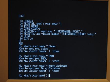
- Boot into a simple integer BASIC program, capable of interactively editing and running its own programs.
- Support multiple programs executing simultaneously, via a pre-emptive multitasking OS.
- Provide keyboard input, VGA video and sound output.
Initial design began in November 2007 with a high-level sketch of the CPU internal design. A simplified Verilog hardware simulation proved the key design details. Construction began in earnest in February 2008, using a large wire-wrap board to interconnect the 50 or so chips needed. In April, a half-finished BMOW 1 booted up for the first time, computing fibonacci(12) = 144 using a simple ROM-based program. One by one the original system goals and stretch goals were met, including VGA video, three voice audio, BASIC, and a bootloader for communication with an attached PC. BMOW 1 eventually gained the ability to run complex programs written in assembly or compiled from C. The main construction phase ended in February 2009, with the completion of a customized case to house everything. As of March 2009, Big Mess o’ Wires 1 is fully functional, but will probably never be “finished”.
Architecture
BMOW 1 borrows liberally from other homebrew designs, as well as the MAYBE design presented in the book Computation Structures by Stephen Ward and Robert Halstead. Data busses are 8 bits wide, and the address bus is 24 bits. Four 8-bit registers are used for general data, and three 24-bit registers store the program counter, stack pointer, and a scratch/working address pointer. Registers and the arithmetic and logic unit are interconnected by one data bus, while RAM, ROM, and memory-mapped hardware devices use a second data bus. The ALU also has dedicated left and right data input busses.
Machine language instructions are implemented as a series of micro-instructions, stored in three parallel ROMs to create a 24-bit microcode word. One micro-instruction is executed each clock cycle, and the micro-instruction bits are used directly as enable and select inputs to control all the chips in the machine. Up to 16 micro-instructions may be needed to implement a single machine language instruction.
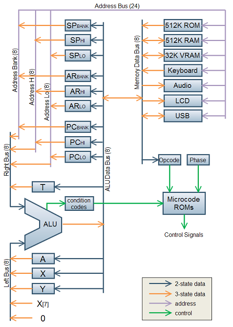
Note: Some additional devices are not shown here, including the VGA display circuitry and real-time clock.
24-bit addresses allow for up to 16MB of memory, but only a little more than 1MB of combined RAM and ROM is installed. The most-significant byte of the address is called the bank byte, and is normally invisible to programs. The standard instruction set presents a 16-bit interface to programs, with most instructions implicitly referencing the current bank. Cross-bank references are possible, but awkward (think x86 segment registers).
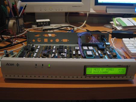
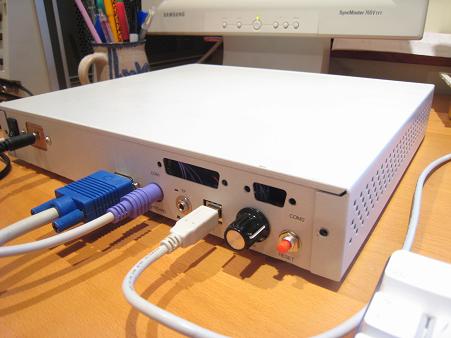
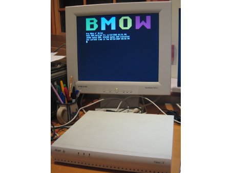
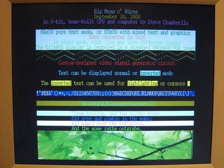
A 512K ROM contains a bootloader/menu program. A USB-to-TTL interface based on an FTDI chip provides an easy way to move data to and from a connected PC. A standard PC keyboard with PS/2 connector is used for keyboard input, and a 24×2 character text LCD serves as a debug output display. Custom video circuitry drives a standard VGA monitor, with a maximum resolution of 512 x 480. A three-voice programmable sound generator provides music and sounds.
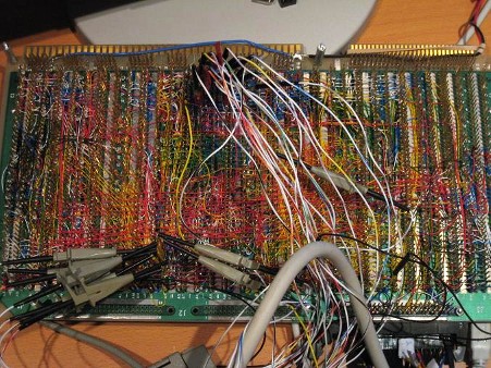
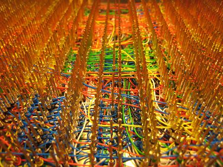
BMOW 1 is built on an Augat wire-wrap board pre-populated with thousands of wire-wrap pins. The chips are pushed into the board without soldering, and can be easily removed, similar to a prototyping breadboard. Unlike a breadboard, the pins are individually connected on the underside of the board according to the needs of the circuit design. A wire-wrap tool is used to wrap stripped wire ends tightly around each pin. Wires can be removed fairly easily in case of a mistake. BMOW 1 contains about 2500 such wire wraps.
Specs
- Current clock speed is 2MHz. It could theoretically go to about 3MHz (untested).
- 512 KBytes of RAM, 512 KBytes of ROM.
- Power draw is 10 Watts, 2.0A at 5V.
- VGA video output is 512×480 with two colors, or 128×240 with 256 colors.
- Audio and music is provided by a three-voice programmable sound generator.
- Keyboard input is a standard PC keyboard with PS/2 connector.
- Debug display is a 24×2 character text LCD.
- There are roughly 1250 wires connecting the components, so 2500 individual hand-turned wire wraps.
Please send me your thoughts and questions!

BMOW 1 Photo Gallery

111 Comments so far
-
Joe - May 30th, 2009 8:47 am
Built any viruses for your machine yet?
Is it really any fun being the last man standing when the rest of the world succumbs?
You and the few other neo ham radio boy scouts will still be up, running, and working your butt off to save the world while the homogenous network suffers a pandemic. Obama is behind. Too little, too late. Next up: Cell phone & Mac virus coordinated with PC & internet (DNS, Apache, IIS) virus. Cyber warfare is here.
– Joe
-
Paul Jurczak - May 30th, 2009 2:04 pm
Impressive, very impressive!
-
Tim Doyle - May 30th, 2009 4:46 pm
We made a much less cool version of BMOW in my CS curriculum.
We smoked a few boards before actually finishing one that worked.
That feeling of “Wow, this actually runs!”, so worth the effort (an entire semester).Great work and presentation on the site. Thanks!
-
def3ctive - May 30th, 2009 7:18 pm
Wow, this is awesome! I’ve always wanted to do something like this but I have always been daunted by the complexity of the wiring. Seeing how well yours has worked has inspired me. Thank you!
-
DK - May 30th, 2009 7:26 pm
WOW,
Some of us like good old VW Beetle.
Some of us like good old MOS6502/MOS6510.
Some of us like good old 8-bit computing (microcontrollers)But to understand this you got to understand what is simple, good and it works.
Excellent Work Steve!!!!
Glad some still understand this Art not many do now days.
Pure 8-bit Art.
Pure 8-bit Art…!
Pure 8-bit Art…..!!!*bow, good job!!!!
-
Steve - May 30th, 2009 9:18 pm
Thanks again to all those who’ve commented, emailed, or stopped by and said hi at the Maker Faire! If you missed it on Saturday, come see it Sunday!
A few of the most common questions people asked were:
– Why didn’t you just use an FPGA? Sure I could have, but I didn’t think that would be very fun. For that matter, why not just write a software simulation of the thing and call it done? No, I wanted to really build the thing to understand it all, not send some VHDL off to a black-box hardwire compiler to be sythesized for a black-box FPGA chip.
– Why didn’t you use a printed circuit board instead of wire wrap? I considered it. For a design that was mostly proven and just needed to be built, it probably makes sense. But I wanted something I could add to as I went, more like working on an experimenter’s board, with the freedom to add, remove, and change pieces as needed.
– Why is there no external storage, like a tape, floppy, or hard drive? Again I considered it, but honestly I just never felt I needed one. Most of the software is cross-compiled on the PC and downloaded, or is stored in ROM. There just isn’t really any non-program data outside the ROM that I found a need to store. If I did, I’d probably just add a second 512K RAM with a battery backup, and treat it as a virtual disk.
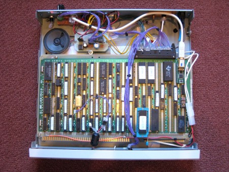
– Where are the wires? That question was on the lips of everyone at the Maker Faire today. I never anticipated that the wires would be more interesting than the computer itself. The wires are the interconnect for all the chips, and are on the underside of the system board. When the board is mounted component-side-up in the case, as shown in the third and fourth photos above, the wires are hidden. If I had it all to do over again, I’d built a case with the system board mounted vertically, and windows cut in both sides of the case, so the components and wires would both be visible.
-
Alek - May 30th, 2009 9:36 pm
Simply _wonderful_ project. That is something worth of remembering for generations to come.
As a professional hardware designer/developer I have a great passion for retro projects like this — even if I ain’t as “retro” as my age can tell –, and I have already created quite complex designs of old arcade games for running in (old) FPGA chips. But this is nothing compared to your achievement.
It is hardly beliavable that this could be actually possible to be done. What about some sort of antenna-effects on real this big mess of wires? What if any wire is broken — did you probe-test them all? More complicated issues, like signal-filtering, problems with inductance or interference, did you have any?
Absolutely mythical. Congratulations!
-
Anonymous - May 30th, 2009 9:41 pm
Привет от красноглазиков!
-
Steve - May 30th, 2009 10:03 pm
@Alek: Thanks for compliments, but hardly as noteworthy you suggest. Lots of other people have done similar projects. A great one is Magic-1, which is in the booth right next to mine at Maker Faire, and deserves twice as much publicity as I’ve suddenly been receiving.
Antenna, interference, and other electrical effects are a problem, but not a large one. The CPU runs at 2MHz, which is comparatively slow. This gives enough time for reflections and other noise to die off before the next clock edge. I tried to avoid laying wires parallel to each other for long distances, to minimize crosstalk. Fan-out limits must be observed, wires kept as short as practically possible, etc. Even so, there are still quite a few signal problems, and some of the signals look pretty horrible on the oscilloscope, yet the CPU still works most of the time. Every now and then it freezes or crashes, which is very likely due to a problem of this kind, but it’s stable enough to run demos and play games with.
As for testing, broken wires, and so forth– my strategy was to build a little, test a little, so I never went very far after new parts and wires were added before I tested everything again. Then when something did go wrong, I could limit the hunt to a relatively small number of recent changes. Wire breakage wasn’t a problem. Once a wire wrap is in place, it’s quite tight and is unlikely to be loosened or broken unintentionally.
-
crowelee - May 31st, 2009 5:43 am
wa,hahahah, strong !!!
-
Anonymous - May 31st, 2009 5:48 am
我代表天朝Cnbeta观光团、豆瓣观光团、草泥马观光团、网易观光团前来祝贺!
-
Anonymous - May 31st, 2009 5:56 am
I represent douban.com tourist party,tianya.cn tourist party,163.com tourist party,Grass Mud Horse tourist party,and cnBeta.com tourist party of PRC,congratulation for your great Works!
-
Lazzaro Leonardo Blog » DIY 8-Bit CPU - May 31st, 2009 7:48 am
[…] LINK […]
-
Safwan Ahmad - May 31st, 2009 11:02 am
Very nice.
-
Kieran Bennett - May 31st, 2009 4:19 pm
Thankyou! That is unbelievably beautiful, you’ve made my day 🙂
BMOW for the win!
-
rapper - May 31st, 2009 9:12 pm
Nice job.
back in the early ’80s we did stuff like this for prototype minicomputers.
18″x18″ wire wrap boards though. You could do a schematic, and send it out to a company that had a machine that would wrap the design (given a layout) automatically with a machien for your initial board. Then you’d start debugging…Power and ground wanted to be handled special (short). clocks were always a problem in terms of routing. Boards were really dense with wires (blue). If I remember right, there was a bypass cap on every part, and that was handled special for short vcc/gnd also.
And then as things got denser, you couldn’t fit all the parts on your target pc board on one wire board, so you’d kludge two and ribbon cable it together. Ribbon cables just made the whole signal integrity problem even worse.
Things went to hell with the fast edge rates of the TTL parts introduced around then.. remember F-series? etc. Basically the fast edge rates and signal integrity issues made it so prototypes had to be PC boards too.
220/330 ohm up/down terminations were your friend for signal integrity issues. I always ended up with variants: 330 up/220 down etc. It was like religion 🙂
We didn’t do any simulation though. You debugged it in the lab. ECOs were in red wire. Each pin was supposed to hold only two wraps. You could fit 3, but that was bad practice. See, on a long net, you wanted to maintain consistency of alternating bottom to bottom and top to top, for each individual wire connecting pins. That way, if you had to break a net, and rewire, you wouldn’t have to take off that many wires. (visualize).
If you used a hand wrapping tool for all the wires, that was a waste. You should have used a gun. Pull the trigger, and it spins the wrap. The trick used to be to be good enough to get it so the wire insulation was wrapped on your last one wrap. Nick the thin wire and you definitely would get a fragile connection.
Oh, and flakeys: if you weren’t careful and dropped wires into the mess, then you’d have flakey intermittents that were hard to find.
I remember one late night where I miswired an ECO, and smoked all the wires in the center of a board. Spent the whole night removing burnt wires and putting new ones back on. Now THAT was a really sucky night. Because you don’t have a consistent description of the current wires. You have to backtrack thru the original netlist and all the ECOs.
-
Thurstan Johnston - June 1st, 2009 7:51 am
Simply amazing stuff! This is really inspirational stuff. Wonder if Steve Wozniak has seen this, I bet he would very interested.
-
jdprueitt - June 1st, 2009 9:37 am
Congratulations on a very successful project.
this must have taken a lot!!!of determination.
maybe you could do a youtube video for all those
college kids who will graduate without ever using
a soldering iron or building ANYTHING digital. -
Hardy - June 1st, 2009 10:34 am
What a waste of time 😉
Just joking … that’s an awesome project!
-
fluud - June 1st, 2009 1:32 pm
What are the dimensions of that thing?
-
Anonymous - June 2nd, 2009 2:24 am
херня полная – у нас в СССР такое собирали в 80-х.
-
Anonymous - June 2nd, 2009 2:53 am
trash!!!!! ссср rulezzzz!!!!
-
Anonymous - June 2nd, 2009 3:09 am
цитата: херня полная – у нас в СССР такое собирали в 80-х.
Согласен с анонимом =) -
Anonymous - June 2nd, 2009 3:41 am
Лично в 10 лет собрал себе такой и было это 1992 году а схема его была взята насколько я припоминаю еще из советского журнала Массовая радио-библиотека за 1989г.
-
Anonymous - June 2nd, 2009 3:53 am
русские физики этим на досуге занимаются)
-
Anonymous - June 2nd, 2009 3:55 am
PS: Да а на хрен столько проводов есть же двухсторонней текстолит непонят.Да и зачем щас сей шедевр ну ностальгия есть а том времени когда комп надо было споять а непросто в магазе купить ну шас не понимаю.
-
LANserv - June 2nd, 2009 5:25 am
хорошая работа, но
по сравнению с тем, что творили (от слова творить, творчество) советские радиолюбители у себя дома – это детский сад: парень купил и склеил по схеме.
—
творчество советских мастеров не прыгнуть никому и не когда !
CCCР – навсегда страна №1
creative activity soviet master not to jump nobody and not when !
USSR – for ever country №1 -
www.ulagsm.ru - June 2nd, 2009 5:32 am
You will need to learn Russian now, after the news appeared on one Russian Resource.
Человек усидчив неимоверно однако, каждую линию спроектировать проложить и закрепить
обычно одно крепишь второе валится
-
www.ulagsm.ru - June 2nd, 2009 5:35 am
An I was thinking that a self-made PC is one I make by screwing up the components from the store in one case like many of us do nowadays…
-
bat - June 2nd, 2009 10:09 am
wow amazing, you’re da fucking GOD man 😉
-
Respect - June 2nd, 2009 10:59 am
Вы не совсем правы. В СССР собирали самопал на готовых процессорах. Здесь процессор выполнен на рассыпухе.
-
Anonymous - June 2nd, 2009 3:37 pm
А в чем сложность та если он его на расcыпухи сделал как не крути все равно это клон Z80
-
Anonymous - June 2nd, 2009 3:58 pm
да вот еще прилагаю к этому кампу еще и ПЗУ на ферритовых кольцах сделать автор тогда еще полгода будет с ним возиться. Да и чеге останавливаться надо вес зделать на логических элементов по 4шт в одной микросхем вопщем выдет 2 симпатичных шкафчика)))
-
Improvised computer - just 1.5 years - June 2nd, 2009 5:15 pm
[…] total, Steve has used about 1250 wires and about 2500 contacts. BMOW project site is located on the address . In addition, Steve Chemberlin even and highly predpriimchiv. Judge for yourself, it offers over […]
-
Respect - June 2nd, 2009 9:00 pm
С чего такая уверенность, что это клон Z80 и почему именно Z80? У него свой 24х разрядный микрокод, зашитый в ПЗУ. Очевидно, что и свой микропрограммный автомат. Никакой из популярных восьмибитников не реализовать на таком мизерном объёме простых кристаллов.
-
User - June 2nd, 2009 9:58 pm
И всё же кое кто не правильно сравнили то, что делали в СССР- там брали готовые детали, ну что то приходилось из мусора собирать. А тут он как собрал и из чего? Вот от сюда то ноги и растут.
P.S. И всё равно кто комп такой собрал- молодец! Если наклейки и майки\футболки с эмблемой уже про даёт- то представьте за сколько такую штукенцию на Ebay продать можно! -
SanSanych - June 2nd, 2009 10:10 pm
Great job! Wonderful!
Excuse me, text below is for lamer above.Для тех, кто в танке:
Дык чтобы понимать, что это не клон ни Z80, ни i8080 – надо знать, какая архитектура у тех была (дело тут даже не в ширине микрокода – тут одноаккумуляторная машинка, банка РОН нет.
А вот для того, чтобы унизить чужую _работу_ и тем самым как бы стать умнее – достаточно ляпнуть единственное “старое” слово, которое человек знает. Можно даже не понимать что это слово означает 🙂 -
Russian Engineer - June 2nd, 2009 10:27 pm
Вспомнилась молодость, когда сам подобных монстрятиков собирал.
Только в наше-то время сие выглядит как мазахизм,
при наличии программируемой логики,
в которую можно не только всю подобную схему
упихнуть почти не напрягаясь, но и покруче наворотить! -
Aq_ - June 2nd, 2009 11:01 pm
Сколько читаю камменты, хамство обнаружил только от русскоязычных пользователей. Теперь я лучше понимаю иностранцев, когда они говорят, что все русские — дебилы и проститутки. Печально ;(
Стив — молодец! Long Life BMOW!
Пусть поскорее выйдет BMOW-2 на SMD-элементах. It should be BMOS, what is the Big Mess Of Solder!
-
Cheap - June 2nd, 2009 11:33 pm
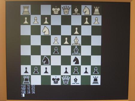
if two computers play each other in chess? Would the computer that went first always win?
-
дебилы и проститутки - June 3rd, 2009 12:17 am
“Сколько читаю камменты, хамство обнаружил только от русскоязычных пользователей. Теперь я лучше понимаю иностранцев, когда они говорят, что все русские — дебилы и проститутки. Печально ;(
Стив — молодец! Long Life BMOW!”
Зы, а мне тебя почему то жаль…может потому что ты инвалид? Уйобывай ка к Стиву жить, я посмотрю как тебя там будут любить ))) интеллигентишка наш ^_#…
P.S. русских везде ненавидят
-
Nicola - June 3rd, 2009 6:24 am
Ха. Ну крут 🙂 Не надо тут показывать знание рус. языка !
Кто выпендривается пусть покажет, что он сделал, а не бросает слова на ветер. -
Anonymous - June 3rd, 2009 6:35 am
Для тех кто щитает что тут Стива унизили ни кто не ково унижать не собирался просто сей произведения не имеет смысла вот и все на данный момент Да и вот чеге еще тем чем собирал его Стив нельзя сравнить с тем чем я его собирал на ГОТОВЫХ БУ ЧИПАХ 18 лет назат (инструмент был разный)вот если бы ему тем деребасам компы липить
PS ДЛЯ НЕПОНЯТЛИВЫХ РОССИЯН Я НЕ ХАМЛЮ СТИВУ Я ТАК ПРОСТО ВЫРАЗИЛ СВАЕ МНЕНИЕ И ВСЕ!!! -
dx4cpc - June 3rd, 2009 8:44 am
skynet!!! Its Skynet!!!! fuck!!!
-
dx4cpc - June 3rd, 2009 8:44 am
me cago en la putaaaaaaaaa
-
Svetlio - June 5th, 2009 1:03 am
Man,
You’re slightly crazy, but I’m amazed. Next project might be transistor based :)! This is hardwared software so hardwired.
You rule! -
Anonymous - June 5th, 2009 3:12 am
你的这个也太牛了吧
-
Brandon - June 7th, 2009 8:37 pm
Lol Steve. Looks like all these people coming here could murder your server. Poor thing, having to serve up to this many people. 😛
-
诗诺比 - June 12th, 2009 12:57 am
真NB呀!!
OurAvr观光团 -
pan - June 12th, 2009 3:20 am
OurAvr观光团


Leave a reply. For customer support issues, please use the Customer Support link instead of writing comments.