

Plus Too Files
Since the Plus Too project hasn’t seen any progress in a year, I’m posting all the design files in the hopes that someone else may want to build on what I’ve done. If you missed the earlier discussions about it, Plus Too is a working replica of a Macintosh Plus, implemented in an FPGA.
Download the Plus Too file archive
What You’ll Need
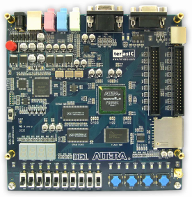
- An Altera DE1 FPGA development board
- A Windows-based PC
- An old PS/2 mouse from a PC (newer USB-based mice won’t work)
- A VGA monitor capable of displaying 1024 x 768 @ 60Hz
Setup Instructions
- Download the Control Panel configuration file DE1_USB_API.sof into the FPGA. This file is included on the CD that comes with the DE1 kit. See sections 3.1 and 4.1 of the DE1 user manual for help.
- Run the DE1_Control_Panel.exe program on your PC. This is also included on the DE1 CD.
- Click on the Flash tab.
- Click the Chip Erase button to clear the DE1 Flash memory.
- In the Sequential Write section, enter 0 for the address and click the File Length checkbox.
- Click the Write a File to Flash button. When prompted, select the plusrom.bin file from the Plus Too archive, and write the file to the DE1 memory. This is a ROM dump from Macintosh Plus.
- In the Sequential Write section, enter 20000 (hex) for the address. Confirm the File Length checkbox is still checked.
- Click the Write a File to Flash button. When prompted, select the Disk608-800K.bin file from the Plus Too archive, and write the file to the DE1 memory. This is a System 6.0.8 boot disk image.
- Download the Plus Too configuration file plusToo_top.sof into the FPGA. This is included in the Plus Too archive.
You should now be up and running! Connect a PS/2 mouse and a VGA monitor for some retro-computing fun.
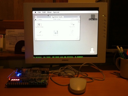
Using Plus Too
There’s no support for the keyboard, sound, or SCSI. The floppy disk is read-only.
Watch out! There’s a bug somewhere that causes PlusToo to crash or the mouse to stop working (not sure which) if you move the mouse around too much or too fast. I’m still not sure what the cause is, but I wrote about it more in a previous post.
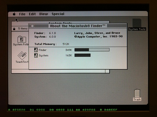
Along the bottom of the screen you’ll see some debug information, shown in green text. From left to right, these are:
- A – the current value on the address bus
- D1 – the incoming value from the data bus
- D0 – the outgoing value from the data bus
- (not labeled) – the current interrupt level
- AA – the previous value of the address bus
- B – the breakpoint address
You can set the breakpoint address using the DE1 switches. When the current address equals the breakpoint address, Plus Too will halt.
The hardware can be controlled using the four push-button switches on the DE1 board, which are labeled Key0 through Key3, as well as the 10 slide switches labeled SW0 through SW9.
- Key2 inserts a blank disk into the external drive. Useful for debugging only.
- Key1 inserts the System 6.0.8 disk into the internal drive.
- Key0+Key1 together perform a reset.
- SW0 selects between free-running (switch down) and single-step mode (switch up).
- When in single-step mode:
- Key0 performs a step
- Key1, Key2, and Key3 load the low, middle, and high bytes of the breakpoint address from switches SW9-SW2.
Making Floppy Disk Images
The Disk608-800.bin file is not a standard floppy disk image file such as you would use with a Mac emulator like Mini vMac or Basilisk II. It’s an encoded file containing data exactly as it would appear on a real floppy disk, complete with sector markers, checksums, and inter-sector timing gaps.
If you want to take an 800K floppy image from your favorite emulator and use it with Plus Too, you’ll need to encode it using my Floppy Encoder utility. It takes a normal floppy image file as input, which usually has a .dsk filename extension, and generates an encoded image file with a .bin extension. The resulting .bin file can then be substituted in step 8 of the setup instructions to run Plus Too with the new floppy image.
Extending Plus Too
The Verilog source files are included in the file archive, for anyone who wants to try taking the project further. The biggest thing it needs now is for someone to set up proper timing constraints. I played around with it a bit, but I didn’t really understand the constraint editor and was eager to move on. PlusToo mostly works without specifying any constraints, but sometimes it will randomly fail to boot up, or exhibit bizarre video bugs. I’ve found that changing the number of signals and sample depth of the Signal Tap logic analyzer setup can fairly predictably make such problems appear and disappear.
The constraints should be:
- External 50 MHz clock
- Internal 32.5 MHz clock synthesized with a PLL. This is the video clock, called clk32 in the Verilog source.
- Internal 8.125 MHz clock named clk8, derived from clk32 with a clock divider. (I couldn’t make this work with a PLL)
- Flash ROM has an address-to-data delay of 70ns. The total delay from clk8 to when all the Flash control and address lines are stable, plus 70 ns, plus whatever the setup time is for the FPGA registers that will receive the Flash data (how do you determine this?), must be less than the clock period of 123ns.
- Similarly for the SRAM, except I believe its address-to-data delay is 10ns (check datasheet). The SRAM should also have additional constraints for write timing.
Read 23 comments and join the conversation
23 Comments so far
Leave a reply. For customer support issues, please use the Customer Support link instead of writing comments.
Thanks for posting the files.
Will be fun to play with!
Cheers,
Red
Thanks!!!!
Thanks for posting the files… I tried it on my DE1 board, and ran into a a problem. When I boot it and insert the boot floppy, after about two minutes, this screen pops up:
https://dl.dropbox.com/u/14283494/Screenshots/Photo%2027-12-2012%2020%2032%2019.jpg
I haven’t been able to figure out how to get past that – is this an issue in the implementation itself, or is this a problem with the flashing of the floppy image?
Hmm, I haven’t encountered that problem before. My first guess is that the floppy disk image wasn’t correctly programmed to the flash memory… maybe only part of the image was programmed instead of the whole thing?
You think you can put this up on Github or something so changes can be tracked more easily? Github also has a issue tracking and project wiki feature that would be nice too if you went with them.
Rok Krajnc who ported minimig to the DE-1 has posted PlusToo to Github:
https://github.com/rkrajnc/PlusToo
Awesome, glad to hear it!
Hi,
First, thank you very much, Steve, for sharing this. Very interesting!
I’m getting the following result:
https://www.dropbox.com/s/f2n0p809mah3z2t/2014-10-24%2008.46.26.jpg?dl=0
Any idea? Am I missing something?
Thanks,
Jonathan
Jonathan, are you in free running mode? See the note about the switches above, and make sure your SW0 is in the down position. Your CPU may just be sitting idle after exiting reset, instead of running the boot code.
Thanks for the quick response. My DE1 is setup in free running mode (SW0 is down). It’s hard to see on the picture as the values seem to be fixed. However, the addresses are looping. I also tried to press KEY1 to “insert the System 6.0.8 disk into the internal drive” without any success.
I made a quick video here: https://www.dropbox.com/s/8tzwuvkcv0w7tyg/2014-10-24%2014.33.01.mp4?dl=0
Thanks,
Jonathan
It’s been a few years since I looked at this, but ROM addresses should all begin with 40 or 41, although I think there’s a brief window during first initialization where it uses addresses in another range like 00. The A value in the debug line (the left-most green number) shows what’s on the address bus, which most of the time will be the current instruction address, and occasionally will be the address of a data fetch or data store. But most of the time you should see a value like 40XXXX for A. If it’s always FFXXXX that suggests the CPU is off executing instructions in some non-existent area of memory, and something’s gone very wrong.
The first thing you should see after a reset (press Key0+Key1 together) is the 50% gray Mac desktop. But it looks like you’re not even getting that far.
Maybe your Mac toolbox ROM wasn’t programmed correctly? I could see this happening if you only did step 9 of the setup instructions and skipped the others. Or maybe in step 7 you forgot to change the write address to 0x20000, and so overwrote the toolbox ROM with the boot disk image.
It might be helpful to try debugging from startup. Put it in single-step mode (SW0 up), then do a reset with Key0+Key1. Then single-step by pressing Key0 repeatedly, and watch what’s happening on the address and data bus. As I recall, the very first thing the 68000 does is to fetch two values from some hard-coded addresses, and use them to initialize the stack pointer and program counter. Then it begins executing code from whatever address the program counter got. I believe the stack pointer is loaded from 000000 and the program counter from 000004. Looking at the ROM listing, it appears the stack pointer will be initialized to 4D1F8172 (which is also the ROM checksum?? this must get reset later) and the program counter to 40002A. Then code should start executing beginning at 40002A.
Hi Steve,
Thanks for all the information. I reprogrammed the flash 3 times total (both plusrom.bin and Disk608-800K.bin) at their documented locations by following all the steps carefully. I event tried with a different monitor to see if it makes a difference. I also rebuilt the project with Quartus II (version 13.0 SP1) to see if it would make a difference and I’m getting the same results. Anyway, the good thing is you have made the source code available so I can spend some time to investigate this on my side.
I will report back when I get some progress.
Thanks again,
Jonathan
Hi Jonathan, et al.
Might be worth checking the manufacturer of the SRAMs on your DE1.
The later models with “ZENTEL” and “PCG”?rams appear to have some issues.
There is a fairly lengthy discussion of the issue, and fixes to be found at:
http://www.minimig.net/viewtopic.php?f=9&t=609
—
Basically, the fix is to add series termination constraints to your QSF file.
(Will also work with the old srams, so no need to maintain two qsf files)
Something along the lines of…
set_instance_assignment -name CYCLONEII_TERMINATION “SERIES 25 OHMS” -to SRAM_CE_N
set_instance_assignment -name CYCLONEII_TERMINATION “SERIES 25 OHMS” -to SRAM_LB_N
set_instance_assignment -name CYCLONEII_TERMINATION “SERIES 25 OHMS” -to SRAM_OE_N
set_instance_assignment -name CYCLONEII_TERMINATION “SERIES 25 OHMS” -to SRAM_UB_N
set_instance_assignment -name CYCLONEII_TERMINATION “SERIES 25 OHMS” -to SRAM_WE_N
set_instance_assignment -name CYCLONEII_TERMINATION “SERIES 25 OHMS” -to SRAM_ADDR[0]
…
set_instance_assignment -name CYCLONEII_TERMINATION “SERIES 25 OHMS” -to SRAM_ADDR[17]
set_instance_assignment -name CYCLONEII_TERMINATION “SERIES 25 OHMS” -to SRAM_DQ[0]
…
set_instance_assignment -name CYCLONEII_TERMINATION “SERIES 25 OHMS” -to SRAM_DQ[15]
An engineer at Terasic also suggested adding these:
set_input_delay -max -clock CLOCK_50 -1.5 [get_ports SRAM_DQ*]
set_input_delay -min -clock CLOCK_50 -1.5 [get_ports SRAM_DQ*]
Hope this helps?
Cheers,
Red
Hi Red,
Thank you for the information. Well, I tried to add termination statements in the QSF file and unfortunately, it doesn’t make a difference.
set_instance_assignment -name CYCLONEII_TERMINATION “SERIES 25 OHMS” -to _sramCE
set_instance_assignment -name CYCLONEII_TERMINATION “SERIES 25 OHMS” -to _sramLDS
set_instance_assignment -name CYCLONEII_TERMINATION “SERIES 25 OHMS” -to _sramOE
set_instance_assignment -name CYCLONEII_TERMINATION “SERIES 25 OHMS” -to _sramUDS
set_instance_assignment -name CYCLONEII_TERMINATION “SERIES 25 OHMS” -to _sramWE
set_instance_assignment -name CYCLONEII_TERMINATION “SERIES 25 OHMS” -to sramAddr[0]
…
set_instance_assignment -name CYCLONEII_TERMINATION “SERIES 25 OHMS” -to sramAddr[17]
set_instance_assignment -name CYCLONEII_TERMINATION “SERIES 25 OHMS” -to sramData[0]
…
set_instance_assignment -name CYCLONEII_TERMINATION “SERIES 25 OHMS” -to sramData[15]
As for the input delays, Quartus II complains that the settings file contains one or more errors. Here’s what I’ve added:
set_input_delay -max -clock clk50 -1.5 [get_ports sramData*]
set_input_delay -min -clock clk50 -1.5 [get_ports sramData*]
I’m trying to figure out why the syntax is invalid.
Thanks,
Jonathan
If you haven’t yet, I would recommend single stepping through the reset and startup sequence, to verify the CPU is at least initializing correctly and executing the start of Mac Toolbox ROM. If not, then the problem is something unrelated to your RAM or termination. But if yes, then you can continue to single step through the boot sequence until you find where something goes wrong.
could you make a newer revision of this?
Maybe just do your own board?
integrate all that you have learned so far, maybe have a Floppy Emu on there,
HD20 as well ? 🙂
maybe integrate a rom that also has 6.0.8 in it like what rob did.
maybe get the PS2 keyboard to work, install a piezo speaker and make the , what 4 channel sound work
maybe pop on a cheap monochrome active matrix display with selectable back light.
give it a little kick stand so it can sit up like a picture, or design a cute panatone case that kinda looks like a MINI PLUS #3
and maybe 2 sd card slots one for the FDD one for the HD20? lol
and just forget scsi. or maybe not? maybe a 422 serial… i guess it would be cool to hook up an image writer,
but again… might totally not be needed.
Then we could do crazy things with it like bring it to work and use it to take notes and word process, or maybe even basic excel and
pop sd out and into modern machine and boom. ? i don’t know… not trying to make more work for you… but you are pretty amazing. i would say i want to be a guy like you when i grow up, the only problem is i’m already 35 🙁 haha
Hi? I have a question about change FLUSH memory in DE1 board. When I start Control_Panel.exe I can’t push any buttons because is disabled? How can I fix this problem?
Hi Steve.
Thanks for this project and the files made available!
I tried to place “Missile Command” game into a 800k 6.0.8 system disk.
Link to game: https://mrob.com/pub/comp/missile20.html
This disk boots fine in mini vmac. Game also runs fine.
I converted with your converter under WinXP – says success.
However, writing the result bin to flash at address 20000 (HEX), the virtual disk cannot be booted?
I checked the file sizes:
Your suuplied 6.0.8 disk bin image: 1.638.000 bytes
My converted 6.0.8 disk bin image: 1.160.000 bytes
Any hints?
best regards, Peter
I barely remember writing that Floppy Converter now. But from looking at the code, it should write 1024 bytes for each of the 1600 sectors which makes 1638400 bytes total. If you only got 1160000 bytes then I think the floppy conversion wasn’t successful. Actually now that I look at it, there are two code sections guarded with #if false that I think should be enabled. I’m not sure why they’re disabled in the source code but I may have been using this for early experiments with Floppy Emu, after Plus Too was finished, and accidentally included the modified version here. Try re-enabling those two code sections and I think you’ll get the expected file size.
The Plus Too core was eventually incorporated into MiST FPGA, where it received many improvements and bug fixes, so you might want to check out that version.
Hi Steve.
I do not have any c# ide/compiler setup.
Could you please update your floppy converter to reenable what is needed, to that I could download your updated converter and give it a try?
Many thanks, Peter
Hi.
Someone with VS compiled it new exe without the #if false und I can confirm, that it works now to create a own 800k disk and use this with plustwo. 😉
Just the instability with mouse is a show stopper – maybe one day, someone will have a second look into this 😉
Thx, Peter
The mouse issue is fixed in the MiST version.
Yes – but I only own a DE1 board. 😉
I hope someday someone with enough knowledge will see, if some code from MIST version can be backported to DE1 plustwo.. Will see..
Thx, Peter