

Archive for April, 2016
Optimizing Assembly (Fast 68K Decompression)

Are you a 68K assembly language guru, or just good at optimizing code? I’m working on a project that’s a replacement ROM for old 68K-based Macintosh computers, part of which involves decompressing a ~5MB disk image from ROM into RAM to boot the machine. This needs to happen fast, to avoid a lengthy wait whenever the computer boots up. I selected liblzg specifically for its simplicity and speed of decompression, even though it doesn’t compress as well as some alternatives. And the whole thing works! But I want it to be faster.
The compressor is a regular Windows/Mac/Linux program, and the decompressor is a hand-written 680000 assembly routine from the lzg authors. It works well, but decompression on a Mac IIsi or IIci only runs about 600K/sec of decompressed data, so it takes around 5-20 seconds to decompress the whole rom disk depending on its size and the Mac’s CPU speed.
The meat of the 68000 decompression routine isn’t too long. It’s a fairly simple Lempel-Ziv algorithm that encodes repeated data as (distance,length) references to the first appearance of the data. There’s a brief summary of lzg’s specific algorithm here. Anyone see any obvious ways to substantially optimize this code? It was written for a vanilla 68000, but for this Mac ROM it’ll always be running on a 68020 or ‘030. Maybe there are some ‘030-specific instructions that could be used to help speed it up? Or some kind of cache prefetch? There’s also some bounds-checking code that could be removed, though the liblzg web site says this provides only a ~12% improvement.
The meat-of-the-meat where data gets copied from source to dest is a two-instruction dbf loop:
_loop1:	move.b	(a4)+,(a1)+
	dbf	d6,_loop1
If any ‘030-specific tricks could improve that, it would help the most. One improvement would be to copy 4 bytes at a time with move.l instead of move.b. But the additional instructions needed to handle 4-byte alignment and 1-3 extra bytes might outweigh the savings for smaller blocks being copied. I think the average block size is around 10 bytes, though some are up to 127 bytes.
The loop might also be unrolled, for certain pre-defined block sizes.
Here’s the entirety of the decompressor’s main loop:
_LZG_LENGTH_DECODE_LUT:
	dc.b	1,2,3,4,5,6,7,8,9,10,11,12,13,14,15,16
	dc.b	17,18,19,20,21,22,23,24,25,26,27,28,34,47,71,127

_lzg_decompress:
	// a0 = src
	// a1 = dst
	// a2 = inEnd = in + inSize
	// a3 = outEnd = out + decodedSize
	// a6 = out
	move.b	(a0)+,d1			// d1 = marker1
	move.b	(a0)+,d2			// d2 = marker2
	move.b	(a0)+,d3			// d3 = marker3
	move.b	(a0)+,d4			// d4 = marker4

	lea		_LZG_LENGTH_DECODE_LUT(pc),a5	// a5 = _LZG_LENGTH_DECODE_LUT

	// Main decompression loop
	move.l	#2056,d0			// Keep the constant 2056 in d0 (for marker1)
	cmp.l	a2,a0
_mainloop:
	bcc.s	_fail				// Note: cmp.l a2,a0 must be performed prior to this!
	move.b	(a0)+,d7			// d7 = symbol

	cmp.b	d1,d7				// marker1?
	beq.s	_marker1
	cmp.b	d2,d7				// marker2?
	beq.s	_marker2
	cmp.b	d3,d7				// marker3?
	beq.s	_marker3
	cmp.b	d4,d7				// marker4?
	beq.s	_marker4

_literal:
	cmp.l	a3,a1
	bcc.s	_fail
	move.b	d7,(a1)+
	cmp.l	a2,a0
	bcs.s	_mainloop

	// We're done
_done:
	// irrelevant code removed
	bra _exit

	// marker4 - "Near copy (incl. RLE)"
_marker4:
	cmp.l	a2,a0
	bcc.s	_fail
	moveq	#0,d5
	move.b	(a0)+,d5
	beq.s	_literal			// Single occurance of the marker symbol (rare)
	move.l	d5,d6
	and.b	#0x1f,d6
	move.b	(a5,d6.w),d6		// length-1 = _LZG_LENGTH_DECODE_LUT[b & 0x1f]
	lsr.b	#5,d5
	addq.w	#1,d5				// offset = (b >> 5) + 1
	bra.s	_copy

	// marker3 - "Short copy"
_marker3:
	cmp.l	a2,a0
	bcc.s	_fail
	moveq	#0,d5
	move.b	(a0)+,d5
	beq.s	_literal			// Single occurance of the marker symbol (rare)
	move.l	d5,d6
	lsr.b	#6,d6
	addq.w	#2,d6				// length-1 = (b >> 6) + 2
	and.b	#0x3f,d5
	addq.w	#8,d5				// offset = (b & 0x3f) + 8
	bra.s	_copy

	// marker2 - "Medium copy"
_marker2:
	cmp.l	a2,a0
	bcc.s	_fail
	moveq	#0,d5
	move.b	(a0)+,d5
	beq.s	_literal			// Single occurance of the marker symbol (rare)
	cmp.l	a2,a0
	bcc.s	_fail
	move.l	d5,d6
	and.b	#0x1f,d6
	move.b	(a5,d6.w),d6		// length-1 = _LZG_LENGTH_DECODE_LUT[b & 0x1f]
	lsl.w	#3,d5
	move.b	(a0)+,d5
	addq.w	#8,d5				// offset = (((b & 0xe0) << 3) | b2) + 8
	bra.s	_copy

	// marker1 - "Distant copy"
_marker1:
	cmp.l	a2,a0
	bcc.s	_fail
	moveq	#0,d5
	move.b	(a0)+,d5
	beq.s	_literal			// Single occurance of the marker symbol (rare)
	lea		1(a0),a4
	cmp.l	a2,a4
	bcc.s	_fail
	move.l	d5,d6
	and.b	#0x1f,d6
	move.b	(a5,d6.w),d6		// length-1 = _LZG_LENGTH_DECODE_LUT[b & 0x1f]
	lsr.w	#5,d5
	swap	d5
	move.b	(a0)+,d5
	lsl.w	#8,d5
	move.b	(a0)+,d5
	add.l	d0,d5				// offset = (((b & 0xe0) << 11) | (b2 << 8) | (*src++)) + 2056

	// Copy corresponding data from history window
	// d5 = offset
	// d6 = length-1
_copy:
	lea		(a1,d6.l),a4
	cmp.l	a3,a4
	bcc	_fail

	move.l	a1,a4
	sub.l	d5,a4

	cmp.l	a6,a4
	bcs	_fail

_loop1:	move.b	(a4)+,(a1)+
	dbf	d6,_loop1

	cmp.l	a2,a0
	bcs	_mainloop
	bra	_done
Another thing to note is that about half of all the data is literals rather than (distance,length) markers, and goes to the _literal branch above. That involves an awful lot of instructions to copy a single byte. A faster method of determining whether a byte is a marker or a literal would help - I plan to try a 256-entry lookup table instead of the four compare and branch instructions.
My final idea would involve changing the lzg algorithm itself, and making the compression slightly worse. For longish sequences of literals, the decompressor just copies bytes from input to output, but it goes through the whole _literal loop for each byte. I'm thinking of introducing a 5th marker byte that means "copy the next N bytes directly to output", for some hand-tuned value of N. Then those N bytes could be copied using a much higher performance loop.
Read 35 comments and join the conversationCapacitor Replacement in a Vintage Power Supply
Capacitors don’t last forever – an unfortunate fact of life for those who collect vintage electronics. The common electrolytic capacitor is one of the most problematic. It’s the type that looks like a little metal can, and after a couple of decades electrolytics tend to start leaking corrosive capacitor goo onto the PCB. You may recognize the strange smell of fish as an early warning sign. Eventually the goo will destroy traces on the PCB, or the changing electrical properties of the capacitor will cause the circuit to stop working. If you want to preserve your vintage equipment, that’s when it’s time for a “recap”.
I have an old Macintosh IIsi computer that dates from around 1991. A few years ago it started acting funny and having trouble turning on, so I sent the logic board to Charles Phillips’ MacCaps Repair Service. He did a great job with the capacitor replacement, and the machine was working great again. But then a few months ago it started to develop new problems that pointed to the need for a power supply recap. I could rarely get it to turn on at all, and when it did, I couldn’t get it to turn off again without unplugging it. Simply plugging the computer into wall power without turning it on caused strange clicking noises from the PSU. And oh, that fish smell.
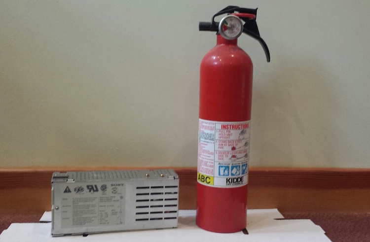
I was going to send the PSU off for a recap. After all, there’s a big warning printed right on the metal cover saying danger, do not open, no user-serviceable parts inside. And while there’s not much danger in a 5 volt logic board, there is a potential for real danger in a power supply drawing 5 amps at 110 volts AC. But then I thought no, I should really get comfortable doing this kind of work myself. I have the tools and the skills, just not the experience or confidence. What’s the worst that could happen? OK, it could blow up and catch fire, but I’ve got a fire extinguisher. 🙂
There are 12 electrolytic capacitors in this power supply, whose types and values are listed here. Two of these are surface mount caps on a daughterboard that’s connected to the main PCB, and the others are all through-hole caps. Because I’m both timid and lazy, I really did not want to replace 12 caps. After reading this discussion thread from someone who did a similar repair, I decided to replace only the three capacitors that seemed most likely to be causing the problem. Two of these were the SMD caps on the daughterboard, which apparently are involved in some kind of PWM control circuit. The third was a 400V cap in the AC section of the power supply. It’s located directly next to some big heat sink thing, and has probably been slowly baking for 25 years.
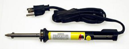
To help with the job, I bought a cheapo vacuum desoldering iron. This makes desoldering of through-hole components easy. Just put the iron over the pin, hold for a second, then press the button to release the plunger and mostly all the solder is sucked up. I used this to desolder the daughterboard too. I had to revisit a few pins to get them totally clean, but overall the process was simple. I don’t do enough desoldering to justify the cost of a fancier desoldering gun with a continuous suction vacuum pump, so this seemed like a good tool for occasional use.
I removed the two SMD capacitors on the daughterboard with a hot air tool. I’m not sure how you would do that without such a tool – just rip them off with pliers? The hot air worked fine, except when I used tweezers to slide off the caps after the solder had melted, I accidentally pushed one of them right through a bunch of other little SMD components, whose solder had also melted, and ended up with a jumbled heap of little components half soldered together in a corner of the board. Ack!!
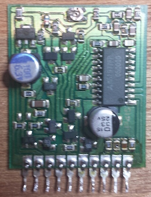
Here’s the daughterboard, before I wrecked it. The four components at bottom right were all pushed into a pile in the corner. A couple of them actually fell off the board, as did one of the pins. But with some patience I was able to separate them all and get things cleaned up, and I think I even put everything back where it was originally. 🙂 After removing the old caps, I cleaned up the board with isopropyl alcohol and a toothbrush to remove the capacitor goo.
The last step was soldering in new capacitors, and putting it all back together. Compared to everything else, that was a breeze.
When the time came for testing, I didn’t take any chances. I brought the whole machine outside, with a fire extinguisher in hand, ready for anything! I plugged it in, pressed the power switch, and… WOOHOO! It booted right up, and everything now looks a-ok. I can boot from the rear power switch or the keyboard power button, and the soft power-off function works again too. I feel like Superman!
This was my first time recapping anything, and I won’t be so timid about recapping next time the need arises. The whole process took about three hours, including lots of futzing around during disassembly and reassembly. If I hadn’t blundered by knocking off a bunch of unrelated SMD parts, I probably could have done the whole job in about an hour.
Read 18 comments and join the conversationIdentify the Mystery Components
I’m planning to do a partial capacitor replacement on the power supply of my old Macintosh IIsi computer. After 25+ years, these capacitors aren’t in the best condition, and the PSU doesn’t work correctly anymore. When plugged in, it makes odd clicking sounds for a few seconds, then does nothing, and the computer won’t boot. Occasionally if I plug it in, unplug it, plug it in again, and say some magic words, I can get the computer to boot. But it’s clearly on its last legs, and the research I’ve done says replacing a few key capacitors will likely fix it.
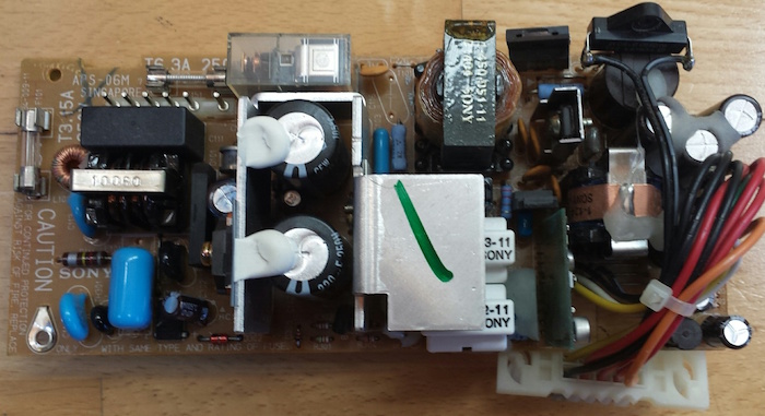
After dismantling the PSU and removing its circuit board, I was surprised by some of the components I found inside. I’ve never looked inside a power supply before, so this was all new to me.
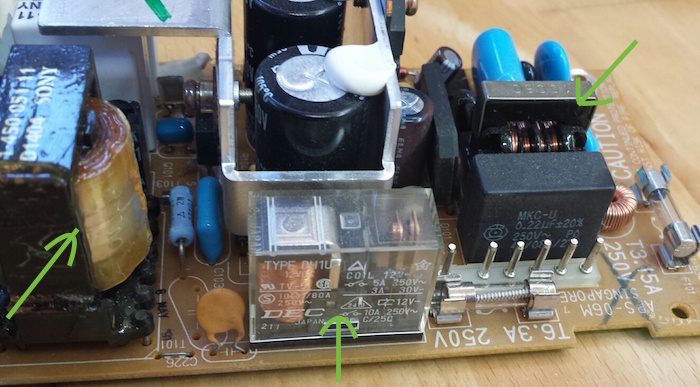
In the center is a relay. I’m not sure why there’s a relay inside a PSU, but there it is. At right is probably a transformer? It has some exposed wire windings, and is located close to where 110V AC comes in, so I assume that’s it. At left is… something. A capacitor? It looks like a rolled up length of plasticized paper, coated in oil.
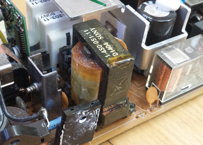
Here’s a closer look at the mystery capacitor thing.
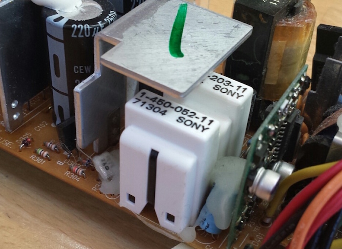
On the other side of the PSU circuit board are two white plastic towers. They look like they might be removable covers. What are these, and what mysteries do they hide?
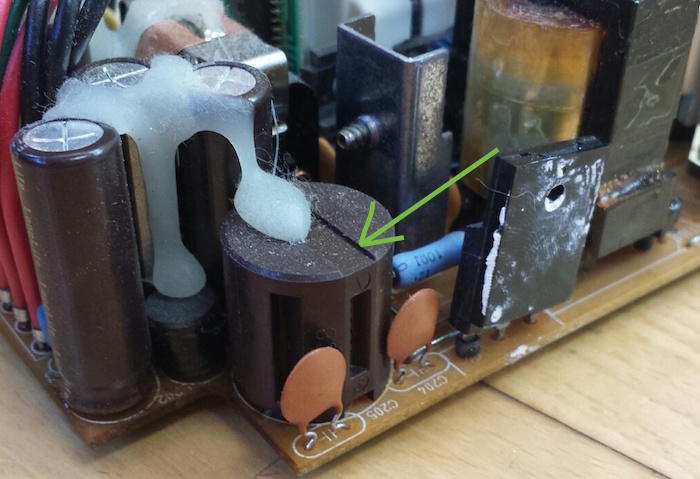

At the end of the board opposite the AC power connection, there are two cylindrical components that look sort of like capacitors, but aren’t. They have vertical grooves cut into them at regular intervals around their circumference. The smaller of the two has 4R7 stamped into its plastic case, and the larger one is marked 830. Could these be some kind of high-power resistor, maybe?
Read 14 comments and join the conversationMore USB-to-ADB Planning
This must be a record for the number of times I’ve posted about a project, without actually building the project, or even a half-way working prototype. I’m still fleshing out my ideas for a USB-to-ADB keyboard/mouse adapter for vintage Macintosh and Apple IIgs computers. In my last update, I described how USB interrupts would interfere with the software timing loops in my bit-banged ADB implementation, and sketched out a few possible solutions to the problem.
After more thought and research, I’ve decided to try the approach that my last post called “timer hacking”. It isn’t really a hack, but rather a better (but more complex) implementation of ADB for the microcontroller. It means removing all the blocking code and software delay loops from my initial ADB implementation, and replacing them with interrupts driven from timers and pin state change events. The ADB-related interrupts will be given higher priority than USB interrupts, and can even interrupt the USB interrupt handler. Because this new ADB code will be interrupt driven, using hardware timers, simultaneous USB activity shouldn’t cause any timing errors. I’m reasonably confident this should all work, but it’ll take time to implement.
I discovered that the PIC32MX I’m using has an input capture feature with a 4-deep FIFO. That will be much nicer than using a basic pin state change interrupt, because input capture records a timer value at the instant a pin changes state, instead of sometime later when the interrupt handler runs and executes code to query the current timer value. So timing measurements when reading ADB will be more accurate. The FIFO means the ADB interrupt handler will only need to be invoked after every 4 rising/falling edges on the ADB signal, instead of for every edge, which will help make things a little more efficient. For writing ADB, I’ll look at using the microcontroller’s built-in PWM hardware, changing the pulse width for each ADB bit, which should be slightly more efficient than using a simple hardware timer to toggle the ADB pin.
Taking a Break
Unfortunately, I can’t actually pursue this plan yet, with the PIC32MX USB Starter Kit II that I’ve been using. This kit has virtually none of the PIC’s pins broken out onto headers, essentially no I/O at all except for the USB ports. Earlier I managed to hack in a single external input by soldering a wire to an unused crystal footprint on the board, which was enough for some simple experiments. But that particular pin isn’t connected to the PIC32MX’s input capture peripheral. Some PIC32MX’s have the ability to dynamically remap the pins, but not this particular one. So in short, I can’t use input capture with this hardware.
Even if that weren’t the case, there are other reasons I want access to more I/O pins. It would be a huge help with debugging if I could connect a serial terminal to the PIC’s UART, and log messages with it. While there’s already a built-in debug-print capability that operates over USB, it seems incredibly slow, on the order of 100 characters per second. And I’d also like additional I/O to experiment with some of this device’s other planned features, like a power-on button connected to ADB’s “on” pin. I’d also like to start testing with the actual model of PIC32MX I plan to use in the final device, instead of the high-end PIC32MX795 in the USB Starter Kit. So it’s time for me to order a bunch of discrete parts, or maybe some much simpler PIC32MX prototyping board, and get working on a real prototype.
The trouble comes when I need to program the PIC32MX on this new board or prototype. Many are designed to be programmed via USB, but I can’t do that if the USB interface is already in use as a USB host. The USB Starter Kit II works around that problem by having two separate PICs, each with their own USB interface, but that’s complex and expensive. The other solution is to use a programmer like a PICkit 3 to program the chip via its ICSP pins, so that’s what I’ll do. Except I don’t own a PICkit 3. I ordered a PICkit 3 clone a while ago from Aliexpress, but it probably won’t arrive for several weeks. Until that happens, I’ll be taking a break from this project, aside from possible further sketching out of ideas on paper.
Read 11 comments and join the conversationToo Many ARMs!
While I’ve been working on my USB-to-ADB converter with a PIC32, I’ve received a steady barrage of feedback saying I ought to consider an ARM Cortex-M microcontroller instead. There are several reasons I haven’t done that, but one of the biggest reasons is that there are simply too many ARM options for me to keep them all straight! Everyone knows what an AVR is, or a PIC, but my mind is a gray blur when it comes to the various LPC, MSP, and XYZ microcontroller offerings based on ARM cores. While having so many ARM options is good from a price competition standpoint, I have to believe this fracturing of the ARM Cortex-M segment hurts it in its competition with AVRs and PICs. If there were only a single big player making and promoting ARM Cortex-M microcontrollers, I suspect they would have made bigger inroads against Atmel and Microchip.
To help clear the mental fog, I decided to make a list of all the ARM Cortex-M microcontroller families I could name off the top of my head, plus any that have been mentioned here recently by commenters. This isn’t meant to be an exhaustive list, but just the options that are mostly likely to be of interest to hobbyists. I did 10 minutes of research into each one, to find some basic info on distinguishing features and pricing. Maybe this will help you, as it helped me. Pricing is Digikey’s lowest listed price for a device with at least 128K of program Flash memory, in a hobbyist-friendly package (no BGA or QFN), and in single unit quantities.
SAMD (Atmel) – ATSAMD20E17A-AU $3.44, ATSAMD21E17A-AU $3.65. ARM Cortex-M0+. Speeds to 48 MHz. 16K RAM. SAMD20 supports USB Device. SAMD21 supports USB Device and Host. A larger version of the SAMD21 is used in the Arduino Zero.
STM32 (ST Microelectronics) – STM32F070CBT6 $2.66. ARM Cortex-M0. This chip runs at 48 MHz, while others in the STM32 family support speeds to 120 MHz. Supports USB Device. STM32L0 family is Cortex-M0+, STM32F1 and STM32F2 families are Cortex-M3. I did a review of an STM32F1 board a few years ago.
MSP (Texas Instruments) – It turns out this isn’t a 32-bit ARM Cortex-M, but a 16-bit microcontroller based on something called CPUXV2. I’m not sure how it got into the ARM part of my brain.
Launchpad (Texas Instruments) – This isn’t a microcontroller at all, but a series of development boards based on the various TI parts. More brain pollution.
Stellaris (Texas Instruments) – A family of higher-end ARM Cortex-M3 microcontrollers priced at $6.50 and up. This is probably not what I’m looking for, but it’s impressive how well TI’s marketing department has infected my brain with their brands. Does TI actually make a low-end ARM Cortex-M microcontroller? I couldn’t find one.
LPC (NXP) – LPC11E67JBD48E, $4.30. ARM Cortex-M0+. 50 MHz. 20K RAM. Other members of the LPC family are Cortex-M0 and Cortex-M3, with speeds up to 200 MHz.
Kinetis (Freescale) – MKL16Z256VLH4, $4.05. ARM Cortex-M0+. 48 MHz. This device actually has 256K Flash and 32K RAM. Smaller Kinetis devices with 128K Flash are available, but are only offered in QFN packages.
PSoC (Cypress Semiconductor) – CY8C5267AXI-LP051, $6.50. ARM Cortex-M3. PSoC 5 @ 67 MHz. 32K RAM. The PSoC 4 is a Cortex-M0 device and also worth considering, but the models with 128K+ program Flash memory are only offered in QFN packages. The interesting thing about the PSoC 4 and 5 families is that they include configurable logic blocks in addition to the standard CPU core and peripherals. It’s like having a tightly-integrated CPLD built into the microcontroller.
Wikipedia has a small reference table that describes some of the differences between the M0, M0+, and M3 cores.
Suggestion to semiconductor manufacturers: if you want to sell a line of microcontrollers that people will actually remember, give it a pronounceable name, instead of some random acronym. Only TI and Freescale did this.
Software and Tools
OK, maybe that list wasn’t too enlightening, other than to identify the major players. If I’m choosing a microcontroller family to invest time in learning, I’m probably less interested in a $0.60 price difference or 4K of extra RAM, and more interested in the quality of the vendor tools, documentation, peripheral libraries, and examples. I’ll also be interested in the availability of low-cost development boards, and the size of the developer community. How do the options listed above compare in those respects? Who’s got a nifty extra feature, like a built-in bootloader, or some cool hardware peripheral, or a software library that doesn’t suck? Leave a comment and tell me your experiences.
The “elephant in the room” when it comes to ARM Cortex-M development is setting up the toolchain. I described this in my old STM32 review, and it wasn’t a fun process, but that was four years ago. Maybe things have gotten better since then? I know some people are perfectly comfortable installing Eclipse along with a plugin from here, a compiler and linker from there, and a debugger from some other place. Personally I’d rather use an IDE that has as many pieces as possible bundled together, so I can skip the setup and spend more time working on my actual project. Since my earlier review, CooCox seems to have remained popular, and something new called Em:Blocks has also grown in popularity, but most people appear to still be rolling their own toolchain.
Read 15 comments and join the conversationMacintosh System Boot Disks

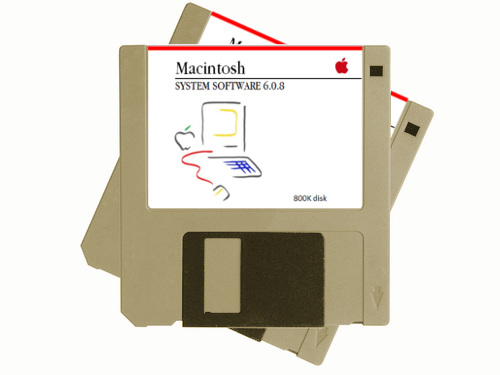
Did you find an old Mac system in the attic, but it won’t boot up? Was your Craigslist impulse buy delivered without any software? Do you need SCSI utilities to format your hard disk, or a terminal program to connect with the outside world? Macintosh system boot disks, applications disks, and utilities disks are now available in the BMOW store. Get rid of that flashing question mark!
This service will create 800K or 400K Macintosh floppies with essential software for your old Mac Plus, SE, Portable, or similar vintage Mac system. It’s all freely downloadable software from Apple and other sources, and I’m offering this service for computer collectors who can’t create 800K/400K disks on their own. These are are DS/DD double-density floppies, written using Apple’s unique variable-speed recording method. The oldest Macs can’t read common 1.44 MB floppies, and PC and USB floppy drives can’t create 800K/400K disks. The only way to create them is with a 25+ year old floppy drive from an Apple computer.
My primary focus is still on the Floppy Emu solid-state disk emulator, which is also available in the BMOW store. It’s a complete Macintosh and Apple II disk emulator solution that supports an unlimited number of disks downloaded from the web, and hard disk emulation too. But sometimes you just need a floppy or two in order to bootstrap that old system, and Floppy Emu would be overkill. If you’re in that position, head over to the BMOW store and pick up a disk.
Read 2 comments and join the conversation