

Reflow Soldering Re-re-re-revisited
This was my 6th *@#&% attempt to assemble some ROM-inator II PCBs using reflow soldering, instead of my normal drag-soldering with an iron. I may not be too bright, but at least I’m persistent. All of the previous attempts failed in slightly different ways, resulting in boards with multiple solder bridges that needed to be cleaned up manually with an iron. This time I altered the way I created a frame for the board being reflowed, and it almost worked. It was certainly the best result so far, but still not good enough.
You can read about the previous reflow attempts here:
1. Reflow with hot air
2. Switched to a hot plate
3. With an aluminum pie pan
4. New solder paste and aluminum sheet
5. Using a stainless steel stencil
My reflow soldering adventures have been a challenge for two reasons:
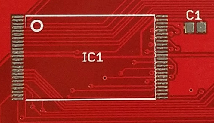
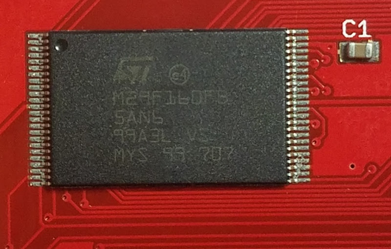
1. The ROM-inator II PCB has two chips with 0.5mm pin spacing, which is very small. If my boards had larger components with more forgiving pin spacing, my earlier attempts would probably have gone much better. 0.5mm might be approaching the limit of what can be done at home without special equipment.
2. I need the PCB to be 100% perfect after reflow, with no manual touch-ups required to fix solder bridges. If this were a one-off prototype, a few solder bridges would be no big deal. But since my goal is to develop a new process that’s faster than hand-soldering, I can’t afford the time needed to do manual touch-ups after reflow.
Floating Stencils
In my previous attempt, I used purpose-made plastic framing pieces to hold the PCB while I applied solder paste with the stencil. These plastic pieces were a tiny bit thicker than the PCB, resulting in the stencil floating above the surface of the PCB instead of resting on it. The amount of float was less than 0.3 mm, but it was still enough to cause problems. This time I used extra PCBs to create a frame, so the thickness was an exact match with no float. The solder paste application looked pretty much spot-on, as you can see here:
Placement of the chips is still difficult. I’m doing it by hand with a pair of tweezers, and the best I can do is to drop the chip within a couple of millimeters of the correct position. Then I slide it around until it’s in the right spot, smearing a bit of the solder paste in the process. Here’s how things looked after chip placement:
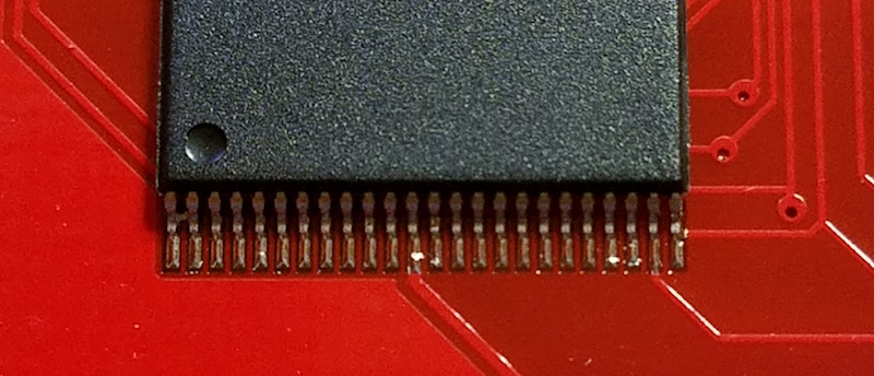
After reflow on my hot plate, the results were pretty good, but unfortunately there were still several solder bridges. Here’s a typical example. It all looks decent, except for those two pins at the far left. The chip also didn’t snap to the correct alignment, as I’d been led to believe would happen thanks to the surface tension of liquid solder. The alignment is pretty good, but not quite centered, and there’s a bridge at pin 1:
I assembled ten boards this way, with two chips per board, and two sides to be soldered per chip, making a total of 40 sides. The good news was that 14 of the 40 sides had zero solder bridges. The bad news was that about half the sides had 2+ solder bridges, and I never assembled a PCB that didn’t have at least one solder bridge on it somewhere. This was the final score:
0 solder bridges: 14 sides
1 solder bridge: 7 sides
2 solder bridges: 7 sides
3 solder bridges: 3 sides
4+ solder bridges: 9 sides
I discovered that I needed to wipe both sides of the stencil clean after each use, otherwise the solder paste application grew progressively messier with each new PCB. I also found that I wasted a lot of solder paste. Dispensing the minimum possible amount from my syringe was still too much, and resulted in a lot of leftover paste on my plastic scraping tool. It was hard to reuse the paste stuck to the scraper. When I tried it a couple of times, using another scraper to clean off the first scraper, the results weren’t good.
End?
Is this the end of my reflow soldering saga? I think so, at least for this particular PCB. I don’t think I can improve further on these results without more effort than can be justified, yet the speed and quality of the process isn’t good enough to replace my current method of drag-soldering with an iron. I’ll revisit this again the next time I have a new PCB to assemble, and I’ll try to stay away from 0.5 mm pitch parts in my designs.
Read 7 comments and join the conversation7 Comments so far
Leave a reply. For customer support issues, please use the Customer Support link instead of writing comments.
Have you seen this guy’s website? http://andybrown.me.uk
He has some projects on there building a reflow oven and seems to have no issues using it to build boards at least as complex as yours.
At very least he might be able to advise you a bit?
Sorry to hear that the reflow continues to frustrate you. The articles I’ve read about it before always make it sound so easy. Apparently you can’t believe everything you read on the internet… 🙁
Steve,
You simply have too much paste. Go back to the stainless steel method, is the best/easiest you can get. Getting the openings the right size is a little bit of an art. It all depends on the thickness of the stencil (most are 0.1mm), pad size and pitch. Then its your own experience with such pitch, but when you have none I suggest cutting in half the length of the pads openings. Less paste is almost never a problem, more is obviously always a problem. I find that making the openings the same size as the actual pads is a bad idea, I always tweak the paste layer to be “just right” but again that comes with experience and varies with each part, pitch, pad geometry etc. For now reduce the paste openings by half or so, I am sure you will get much better results.
When you apply the paste do 2 motions: one gentle one to spread the paste in an even layer over the pads, then one sharp 45 degree angled motion to wipe it off. The stencil should be CLEAN on the bottom side and ideally no paste caught up in the openings (mostly a problem when it’s dried up because it reduces the paste deposition). If you jog back and forth and push the paste more than once then it starts to get under the stencil and in between the openings creating the gooey mess of paste that then produces bridging. You only want as much as the openings allow.
Try again, when you get it once and twice and a few times in a row then you get the AHA moment and it makes you feel great 😉
Then cooking them is the easiest part, almost 😛
Yeah, it’s very possible the openings in the stencil are bigger than necessary. I used the same stainless steel stencil as with the previous attempt. Most of the boards were done with a single slow wipe of paste across the stencil, though a couple required multiple passes. I couldn’t visually see paste getting stuck under the stencil, but my first few attempts grew progressively worse until I started cleaning the underside after each use. I’m not sure if it’s a problem with how I’m applying the paste, or if I’m smearing it when I lift off the stencil.
One more issue I forgot to mention: I often had to reposition the stencil between one use and the next, even though I was using the same frame and had the side of the stencil taped in the same place. If each PCB was identical, then in theory I should have been able to slide the next PCB in and lower the stencil back down for perfect alignment with the pads. But it seems there’s a tiny variation in the exterior dimensions of my PCB, or the edges just aren’t smooth. It’s enough to throw the stencil alignment off by roughly the width of a pad, about 0.2 mm.
FWIW you can reuse the old stencil rather than reorder, use clear tape to cover half of the pads on the bottom side, for each column of openings.
I’m starting to think I might be better off with a reflow toaster than a reflow hot plate. I chose the hot plate because it’s less likely to melt delicate plastic parts, it’s easier to see what’s happening during reflow, and it consumes much less space in my crowded office than a toaster would. But I’ve discovered some big downsides to the hot plate:
– The hot plate remains hot for a LONG time after it’s turned off. Like 10-15 minutes.
– It’s hard to get the PCBs off the hot plate when they’re done reflowing, without burning myself. I can’t just leave them sitting on the hot plate to cool, since it retains heat for so long.
– The surface area of a hot plate is small compared to a toaster, so I can’t reflow as many PCBs at the same time.
I can definitely recommend using a toaster: I’ve been using a $40 toaster with manual temperature control only and am very happy. The process is surprisingly forgiving, and I got pretty good results on my first couple runs, and can get great results now.
I dug up a blog post from the first time I tried the toaster out:
http://blog.kevmod.com/2013/10/quadcopter-update-bldc-boards-ready/
I got all the nice self-correcting properties that you want from this process (chips align, bridges will break, etc). If you’re set on the hot plate, it might be worth trying increasing the temperature so that the solder flows better. If you’re using lead-free solder, it might be worth trying out leaded solder to nail down the process first.