

Archive for the 'Yellowstone' Category
Yellowstone Manufacturing is Go!
![]()
The i’s are dotted, the t’s are crossed, and Yellowstone manufacturing is underway! I want to say something satirical like “I never thought I’d live to see this day”, but truthfully this has been a long, long, loooooooong time in the making. General availability of Yellowstone is expected sometime around the middle of March. Development started in the summer of 2017, so you can do the math on total development time.
I’ve created a Yellowstone product page. This will be the official home for everything Yellowstone, including an overview of what it is and why you might want it, compatibility information, links to the instruction manual, firmware updates, and more.
Yellowstone is a universal disk controller card for Apple II computers. It supports nearly every type of Apple disk drive ever made, including standard 3.5 inch drives, 5.25 inch drives, smart drives like the Unidisk 3.5 and the BMOW Floppy Emu’s smartport hard disk, and even Macintosh 3.5 inch drives. Yellowstone combines the power of an Apple 3.5 Disk Controller Card, a standard 5.25 inch (Disk II) controller card, the Apple Liron controller, and more, all in a single card.
Need to attach a disk drive to your Apple II? Yellowstone should be your first choice, because it does virtually everything that every other Apple disk controller can do, plus more. The retail price for Yellowstone is planned somewhere in the mid-$100s range. This is a nice value, given that an Apple 3.5 Disk Controller Card costs $200+ and used Liron cards sell for $300+ on eBay, and Yellowstone can do much more than either of those cards.
Apple Disk Controller Card Comparison
| Disk Controller | Supports 3.5 inch drives | Supports 5.25 inch drives | Supports smart hard drives | Supports Macintosh drives | 20-pin ribbon connector | DB-19 connector | Number of connectors |
| Disk II Controller Card |
✔ | ✔ | 2 | ||||
| Disk 5.25 Controller Card |
✔ | ✔ | 1 | ||||
| Apple 3.5 Disk Controller Card | ✔ | ✔ | ✔ | 1 | |||
| Apple Liron Card | ✔ | ✔ | 1 | ||||
| Yellowstone | ✔ | ✔ | ✔ | ✔ | ✔ | ✔1 | 2 |
[1] optional DB-19F connector
Since I know people are going to ask, I’m not taking pre-orders at this time, but you can sign up for the BMOW Newsletter if you want to be informed when Yellowstone is ready for sale. There should be plenty of Yellowstone cards to meet demand for at least a few months, so there’s no worry of an immediate sell-out. But in the medium to long term, the global semiconductor shortage and general meltdown of supply chains will be a problem. I couldn’t build additional Yellowstone cards right now, even if I wanted to, because the necessary parts just aren’t available anywhere. So if you want one of these, maybe don’t wait too long beyond March to grab one.
Want all the nitty-gritty usage details? You can read the Yellowstone instruction manual here. Now the waiting begins…
Read 23 comments and join the conversationAlmost Manufacture-Ready
As 2021 draws to a close, Yellowstone is very nearly finished, with just a few details left to iron out. I recently tested a new v2.3 prototype with a couple of small PCB changes, and so far it’s looking good. The new PCB fixes an obscure problem with the Unidisk 5.25 and Disk IIc, where one of those specific drives connected as Drive 2 would interfere with another 5.25 inch drive at Drive 1. Initially I’d planned to write this off as a known compatibility issue, but I had second thoughts, and rushed through a new PCB revision.
Parts sourcing continues to be a major problem. The good news is that I was able to find more of the FPGAs that Yellowstone needs, but I had to go through a third-party dealer in Hong Kong and pay roughly twice the normal price. I have enough parts now to manufacture about 500 Yellowstone cards. Beyond that, the outlook is murky. I expect the semiconductor shortage to get worse before it starts getting better, and many parts are currently quoting lead times of a year or more. Given the current environment, Yellowstone should probably be considered a “limited edition” in 2022, with the possibility of some restock in 2023 or 2024.
I’ve received a couple of manufacturing quotes already from CircuitHub and MacroFab, two vendors with automated web-based quoting tools. These are helpful sanity checks and estimates, but they’re not yet fully baked quotes that I could move ahead with as-is. Optional features like beveled PCB edges and gold fingers require a custom quote. Programming and testing requirements are also difficult to factor in to automated quoting tools.
The preliminary information looks like beveled PCB edges and gold fingers would add about 30 percent (combined) to the total cost. I don’t know the cost breakdown between the two features. 30 percent is quite a lot, and I’m debating whether people will be willing to pay 30 percent more for a card with these features. The prototypes have square edges and ENIG fingers, and it doesn’t seem to have been an issue for the beta testers, so I’m leaning against including these extra features.
I talked to the support staff at Circuit Hub, and they were reluctant to discuss using my own-designed Yellowstone tester. They felt that the quality of their assembly process was so high, with automated visual and x-ray testing, that additional functional testing was unnecessary. And they stressed that if an assembly problem were ever found, I could send the board back to them for free rework. I admit to lacking experience here, but this makes me uneasy. It puts the onus on me to actually test each board before it’s sold, instead of having the vendor do it, but that’s exactly the type of work I want to outsource. And it assumes that free rework would make it acceptable to receive faulty boards. The cost of faulty boards is mostly lost time for testing and troubleshooting, not the cost of rework. By the time I’ve tested a board myself, confirmed that it fails, diagnosed the problem, and identified it as an assembly problem, I could probably just fix it in five minutes with a soldering iron. I’m not going to ship a board back for that. But I don’t want to be doing that kind of work in the first place. To be fair, they did say they would do functional testing if I really wanted it, but their process doesn’t seem to be designed for this, and they implied that it would be expensive.
I have the general impression that the automated quoting vendors like CircuitHub and MacroFab are geared more towards low volume prototyping, or simple projects involving common parts. I think they may not have the most competitive prices either, but we’ll see. For anything slightly non-standard, or for the most competitive pricing, I think it may still be necessary to go the traditional route of phoning or emailing a vendor, and having an actual person-to-person discussion about manufacturing options and requirements. I’ll be doing that soon.
One other interesting option is Seeed Studio’s Fusion PCB service. They have a semi-automated quoting tool, but the tool still needed some manual help to finish my quote, and even then it wasn’t entirely correct. However, the total quoted cost was less than half the cost from the two other vendors. They even agreed to include functional testing for free, but other options like beveled edges and gold fingers don’t seem to be available at all. The big downside is the two-way trans-Pacific shipping that would be needed. I would need to ship all the FPGAs to them for assembly, which they don’t really like doing, and which would create extra paperwork hassles and tax/tariff concerns. I would still prefer to work with a local vendor, or at least a vendor in the same country, if I can find one that’s competitive.
Most vendors are quoting lead times of about two months, so if I can get started with manufacturing soon, I could have product ready for sale by March. The lunar New Year holiday is fast approaching though, and that usually shuts down most Chinese businesses for a couple of weeks. That may delay the schedule, depending on what vendor and manufacturing process I ultimately choose. But barring any further unexpected problems, final Yellowstone cards should be available by March or April at the latest. Woohoo!
Read 6 comments and join the conversationEdge Connectors, ENIG Plating, and Galvanic Corrosion
Yellowstone is inching slowly towards the start of manufacturing. One question that’s arisen is the type of surface plating to use on the PCB. The default / cheap plating is HASL or Hot Air Solder Leveling, which is just a thin layer of solder, consisting mostly of tin. This is what BMOW’s other products use. But engineering wisdom says that for an edge connector, or any PCB surface that will send electrical signals across a mechanical contact surface, you should use ENIG plating. ENIG is Electroless Nickel Immersion Gold, and it’s a layer of nickel covered in a second layer of gold. It’s more expensive, but more durable.
So ENIG then? Well, maybe not. I recently learned about a problem called galvanic corrosion that occurs when two dissimilar metals are in contact for a long time. The peripheral card slots in an Apple II computer have tin fingers, I believe – at least they’re not obviously gold-colored. Does that mean an ENIG plated board inserted into an edge connector slot with tin fingers is doomed to contact corrosion and premature failure? A quick check of other Apple II peripheral cards in my office showed they all have gold-colored connectors. I’m uncertain if they’re ENIG or something else, but probably ENIG.
Read 9 comments and join the conversationCircuit Sleuthing: Unidisk 5.25 Enable and PHI1

While chasing down some Yellowstone hardware bugs, I discovered an unexpected analog-type behavior on the enable input of the Unidisk 5.25 (A9M0104). This is an active low digital input that’s used to enable or disable the disk drive. Under the right conditions, something inside the drive itself is creating a substantial load on this input signal, or actively driving the signal. So instead of a nice clean 0 to 1 transition, I see stuff like the graph shown above. When the intended enable output from Yellowstone switches from low to high, the actual signal climbs from 0V to about 3.3V (on a 5V system) for about 50 microseconds, then quickly drops to 1.2V, then starts slowly rising. Then about 250 microseconds later when the PHI1 input switches from high to low, the enable signal crashes to 0V before quickly recovering to 2.9V, and eventually reaching 3.3V again. This causes buggy behavior and errors. Hmmm.
This problem only happens when PHI1 is high at the time when the enable signal is de-asserted. If PHI1 is low, the the enable signal follows a clean transition from 0 to 3.3V:

If PHI1 is high, but remains high forever instead of transitioning like the first example, then there’s still trouble with the enable signal, but the crash to 0V doesn’t happen:

The Unidisk 5.25 isn’t a very common drive, and many Apple II collectors have never heard of it. For comparison, here’s a repeat of the first example with a common Disk II drive instead of the Unidisk 5.25. There’s something strange, but it’s not as severe, and the crash to 0V doesn’t happen:

That’s all the evidence. Now let’s look at some schematics to try and determine what’s going on here.
Schematics Research
Yellowstone has two independent disk connectors. This weirdness with the enable signal only happens when the drive is connected to Yellowstone’s J2, which uses a different method than J1 to create the enable output. For J1, the enable signal is actively driven high or low by a 74LS244. But for J2, the enable signal is actively pulled low by a 74LVC07, and passively pulled high by a 10K pull-up resistor to +5V:
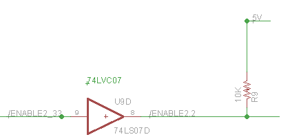
This creates a weak enable high signal for J2, which is certainly part of the problem here. But before saying “you shouldn’t do it that way”, I’d like to understand why this doesn’t work here, and what exactly is going wrong.
The first oddity is that even when the system’s at rest, the enable voltage is about 3.3V rather than the expected value around 5V. Since the high signal comes from the 10K pull-up resistor, the voltage should theoretically be about 5V as long as nothing in the drive is consuming more than a tiny amount of current from the enable signal. So it seems something in the drive *is* consuming appreciable current from the signal, or is otherwise influencing the signal voltage.
The second oddity is PHI1’s influence. What does PHI1 have to do with anything, and why should it affect the enable voltage? The PHI0 to PHI3 inputs are normally used to control the stepper motor for switching between tracks on the disk. But the PHI1 signal also has a second purpose related to the write-protect detection circuit:
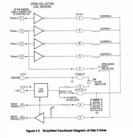
You can confirm this by checking the schematic for the Disk II analog board, although the write-protect switch itself isn’t shown:
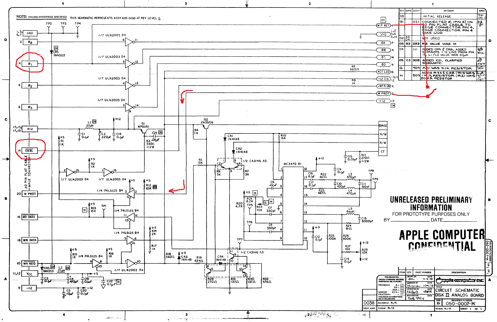
(click the image for a hi-res version) PHI1 is routed through the write-protect switch and becomes the value for the WPROT output, and is also used to gate the WRREQ input and prevent writing to write-protected disks. This explains why PHI1 is different from PHI0, PHI2, and PHI3, but not how it might affect the ENABLE input signal’s voltage.
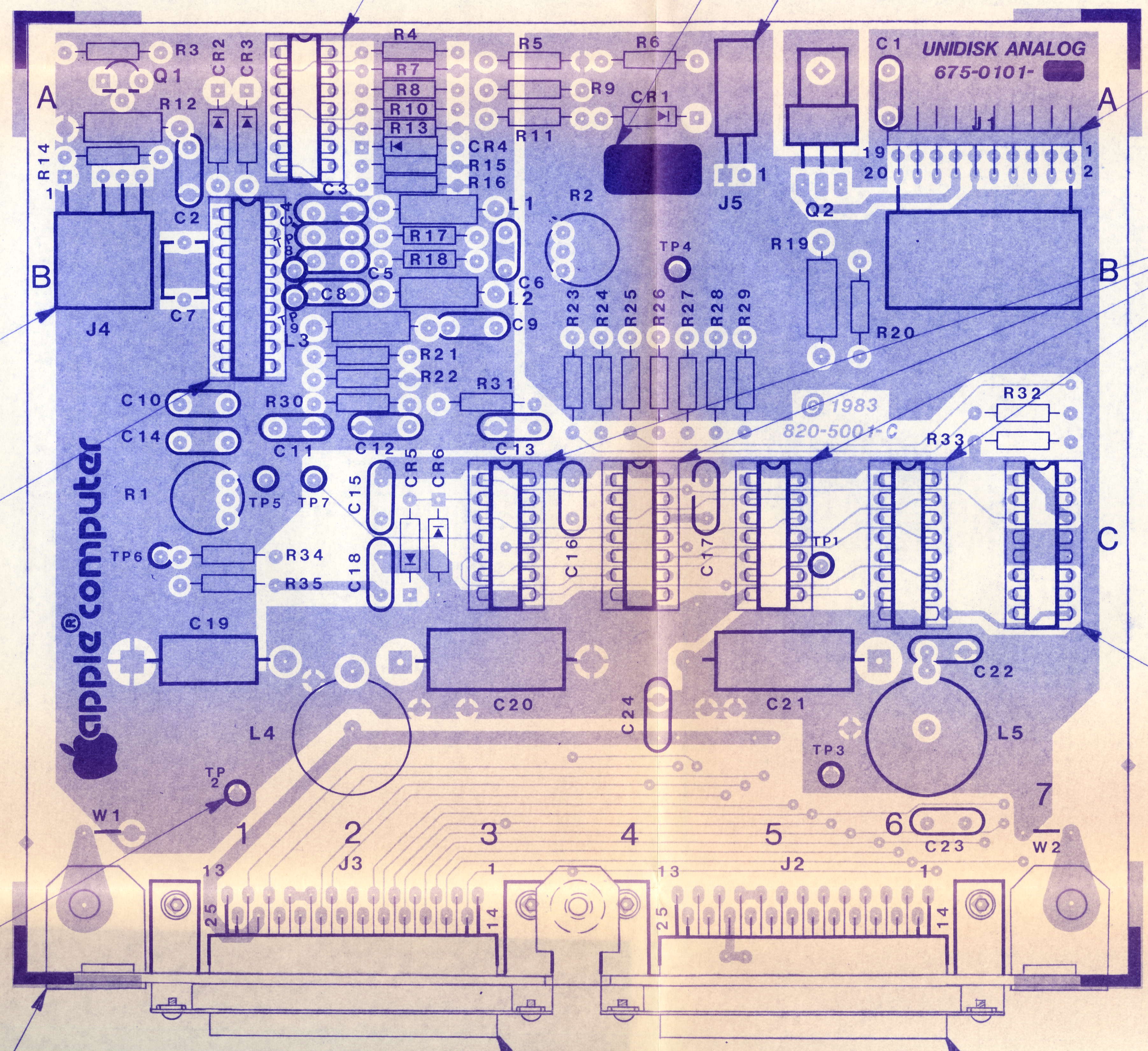
That’s the Disk II. What about the Unidisk 5.25? It should be very similar, but unfortunately I can’t find any reliable schematic of the Unidisk 5.25 analog board. There’s this Unidisk 5.25 schematic, but I’m not sure it’s what it claims to be. It shows a drive with two 25-pin connectors, but the Unidisk 5.25 only has a single 19-pin connector. There’s also this Unidisk 5.25 PCB image, but it also shows two 25-pin connectors. I think both of these may actually be for the Duodisk, or for some never-released prototype, rather than for the A9M0104 Unidisk 5.25. So we’re forced to guess about what’s inside the Unidisk 5.25, with the knowledge that it’s mostly the same as the Disk II except with a half-height drive instead of full height.
A few things on the Disk II analog board schematic are noteworthy. The ENBL input has a 1K pull-up resistor to +5V (R1), so the 10K pull-up on Yellowstone isn’t relevant or necessary for this particular drive. ENBL is connected to three digital inputs. Two are 74LS inputs with input current about 0.1 mA, and the third is some type of inverter/transistor array with an input current around 1 mA. That’s a fairly large amount of input current. If my math is right, 1.2 mA though the 1K pull-up resistor R1 would drop 5V down to 3.8V, which is at least in the general neighborhood of the 3.3V that I measured.
ENBL is also connected through a 1K series resistor R9 to something called -MTRON. That’s not shown, probably because it’s part of the Shugart drive mechanism and not the analog board. What’s there? Given the series resistor and the fact that ENBL is active low, I’m guessing maybe there’s a PNP transistor at -MTRON? What else is there? Could this be the source of all the strangeness?
When the write-protect switch is closed, PHI1 will have an extra 10K pull-up to 5V at R12. It will also be connected to a couple of 74L125 inputs. But I don’t see any capacitors or other interesting details on the PHI1 circuit path that might explain what’s happening. Except for the power supplies, I don’t see any inductors or capacitors anywhere that look like they might cause the weird behavior I’ve observed.
Could the +5V supply inside the Unidisk 5.25 be changing? It’s isolated from the external +5V input by an inductor, so it’s possible. And resistor R1 would cause any large change on the internal +5V to influence the ENBL voltage too.
It’s worth mentioning that the Unidisk 5.25 is known to have something strange about its write-protect circuit behavior, and the drive isn’t compatible with the Apple IIgs ROM 03. But I’ve never found any definitive explanation for just what it is about the Unidisk 5.25 that’s different. I discussed this in another blog post from a few years ago, but in a different context, and my information about the Unidisk 5.25 was mostly speculation:
There’s also a Unidisk 5.25 analog board Twitter thread in which another Apple II hacker pondered some of the same questions about the write-protect circuit, but I don’t think he ever found answers.
According to some Yellowstone beta testers, the Disk IIc A2M4050 also has similar problems when it’s connected to Yellowstone’s J2. I don’t have a Disk IIc, so I can’t confirm if it’s the same enable voltage problem as the Unidisk 5.25, but I’d bet it is.
Solutions?
Without knowing exactly why the Unidisk 5.25 behaves this way at Yellowstone’s J2, I can still see a few potential solutions.
The easier solution is to make the enable signal’s pull-up stronger, so it more closely approximates an actively-driven signal’s logical high output. I was able to test this by paralleling an additional resistor with Yellowstone’s pull-up. I tried successively smaller and smaller pull-up resistor values (stronger pull-ups), and the enable signal gradually improved, and the “crash to 0V” became a crash to 0.5V, then 1.0V, etc. With 470 ohms in parallel with the original 10K ohms, the low point of the crash was improved to 2.0V and the drive began working normally. This solution acknowledges that something unexplained is pulling ENBL low, so it compensates by pulling ENBL high more strongly. But it doesn’t actually explain the problem, and it means about 12 mA would be wasted in Yellowstone’s 74LVC07 whenever J2’s enable is driven low.
The better solution is probably to redesign the Yellowstone PCB, so J2’s enable can be actively driven high and low, instead of using the ’07 and a pull-up resistor. Then J2’s enable circuit would match J1’s. I didn’t do this initially because I ran out of buffer pins, and didn’t want to add another chip just for this one signal. Even now, when I consider the prospect of revving the PCB yet again, and going through another round of verification and beta testing, I feel sick.
A possible third solution might be to leave the hardware as-is, and solve the problem in firmware. Since I’ve characterized the problem and when it happens, maybe I can tweak the firmware to avoid it. For example, maybe I can ensure PHI1 is always low before J2’s enable is de-asserted, or else insert a few milliseconds of blanking time whenever J2’s enable is de-asserted, to ensure nothing else happens while the enable signal voltage is acting strangely. But any firmware solution would be more like a bandage than a true fix, so it’s probably better to identify and fix the root cause.
Read 5 comments and join the conversationApple IIgs 80 Column Mode Crash
Here’s the part of our program where I describe a problem I’m having, and somebody tells me what I’ve done wrong, because I’m not smart enough to figure it out myself. The problem is with the Yellowstone disk controller, the Apple IIgs, and 80 column display mode. It’s a minor issue, but so far it’s defeated my attempts to fix it.
If you hold the Control-D keys during boot-up, Yellowstone will change its behavior and briefly display a text message “YELLOWSTONE DISK II MODE”, then continue booting. This works well on all the computers that the beta testers and I have tried, except for the Apple IIgs when the display type is set to 80 column mode. In this one case, the computer immediately crashes into the Apple II monitor when cold booting and holding Control-D.
- Holding Control-D during a reset works OK. It only crashes from a cold boot after you turn on the power switch.
- If the IIgs display type is set to 40 column mode, it works OK.
- If I replace the calls to HOME and COUT (the ROM’s text output subroutines) with NOP instructions, then it doesn’t crash anymore in 80 column mode, but I don’t get my text either.
I’m guessing there is 80 column firmware somewhere that’s not yet initialized during a cold boot, or that some Apple II soft switches for 80 column mode aren’t yet configured. That would explain why it works OK when I reset the computer with Control-OpenApple-Reset, and only fails from a cold boot. I vaguely recall reading somewhere that 80 column support is implemented as a virtual peripheral card in slot 3, which won’t have been initialized yet when my card in slot 6 is being initialized, because higher numbered slots are initialized first.
According to the docs, the soft switch at address $C00C will turn off 80 column mode. I tried making the Yellowstone firmware touch this address before calling HOME and COUT, but it still crashes. I also noticed that touching $C00C interactively from the Apple II monitor prompt will turn off 80-column mode but also locks up the computer with a weird animating pattern, so I’m not sure that’s the correct method of disabling 80-column mode. These Apple II soft switches can sure be challenging to understand.
Read 6 comments and join the conversationYellowstone Beta Testing Continues
The goal of a “do everything” disk controller for Apple II is getting closer to reality, thanks to the efforts of the hard-working beta testers. If all goes well, I’m hoping to have Yellowstone cards available for sale in the first months of the new year. Yellowstone is designed to support virtually every type of Apple 5.25 inch, 3.5 inch, or smart disk drive that exists, including Macintosh drives running on the Apple II, and the results from the beta testers have been very encouraging so far. But it’s not all perfect. Here are a few of the issues that beta testing has uncovered.
Unidisk 5.25 and Disk IIc Problems at Drive 2
The Unidisk 5.25 and the Disk IIc work fine when connected as Drive 1, but in some situations they appear to interfere with Drive 1 if they’re connected as Drive 2. I don’t have the hardware needed to troubleshoot this one directly, but I should be receiving a Unidisk 5.25 next week. My best guess is that the outputs on these drives have a different type of driver circuit than other drives, which causes the tri-state signals to take longer than normal to get pulled to a logical “1” voltage by Yellowstone’s pull-up resistors. So their “0” outputs effectively overlap with Drive 1’s. Or it may be something completely different.
Third-Party 3.5 Inch Drive Problems
All of the Apple-brand 3.5 inch drives are working, including the Apple 3.5, Unidisk 3.5, Apple SuperDrive, and various Macintosh 3.5 inch drives. But third-party drives from Applied Engineering, Dataspace, Ehman, and Laser only work sporadically or don’t work at all. The Applied Engineering 3.5 drive is supposed to work with a stock Apple IIgs, but the other three reportedly don’t work with any stock Apple computer or disk controller, but do work with the original UDC disk controller. (It seems like that would have greatly limited their sales appeal.) I have a Laser 3.5 for testing, and I should be receiving an Applied Engineering 3.5 drive next week.
Obscure Crash on Apple IIgs
If your IIgs is configured for 80 column mode, and you use one of the several methods to enable Yellowstone’s Disk II mode immediately from power-on, it will crash. This doesn’t happen after a warm start or reboot, only directly from power-on. It also doesn’t happen in 40 column mode. I suspect my code that prints “YELLOWSTONE DISK II MODE” is doing something bad in 80 column mode. It just calls the HOME and COUT routines in the Apple II ROM. I haven’t looked into this further yet.
3.5 Inch Disk I/O Speed
Depending on what software you’re running and what you’re doing with it, 3.5 inch disk I/O through Yellowstone is anywhere from a little to a lot slower than 3.5 inch disk I/O with the same drive on the Apple IIgs built-in disk port. 5.25 inch disk I/O and smart disk I/O (like the Unidisk 3.5 and Floppy Emu Smartport Hard Disk) are about the same speed as the Apple IIgs built-in disk port. I’m not sure why 3.5 inch I/O is behaving differently, but it may be some combination of sector interleave and code optimization.
Possible Disk Corruption with VidHD
One tester reported that a specific Apple IIgs hardware configuration including VidHD would corrupt 3.5 inch disks during power-up. When VidHD was removed, the problem disappeared. I think this is actually a VidHD problem and not Yellowstone. There was a long discussion on Facebook’s Apple II group earlier this year about people experiencing disk corruption when using VidHD. Initial reports were that the latest firmware fixed it, but that was later called into question.
Possible Problems with TransWarp Accelerator
One tester reported problems when running Yellowstone on a specific unenhanced Apple IIe system with a TransWarp accelerator. The problem didn’t appear with the TW on a different computer, and couldn’t be confirmed by the only other tester with a TransWarp. For now it’s unclear if this is a Yellowstone problem or something else.
Cable Routing Difficulties
A few testers reported that the disk ribbon cables were difficult to route through the opening in the rear of the computer, or that the cables pushed against the card in the neighboring slot. I’ve experimented a bit with using right-angle connectors and some other ideas, but there’s probably nothing much I can do without changing the entire board layout. I think the testers experienced this frustration more often than a typical user will, because the testers are constantly plugging and unplugging different drives in order to verify them.
There are a few more open issues beyond these, but most of them are hopefully at the level of errata, and don’t need to delay production of the final Yellowstone cards. Any Yellowstone firmware bugs that are discovered after launch can be fixed with a firmware update, which can be done in-system on the Apple II computer without any special programming tools.
Be the first to comment!