

Archive for the 'Yellowstone' Category
Clock Glitch
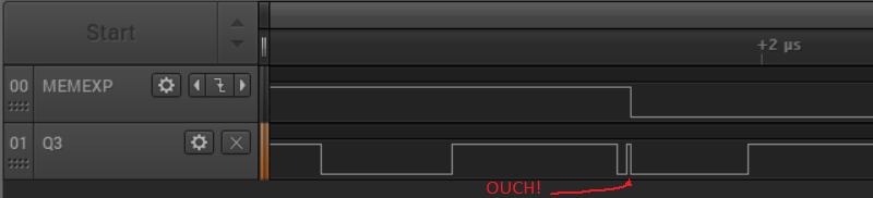
I’ve found a rare clock glitch in the Yellowstone hardware, but I’m not sure how to fix it. This seems to be the source of the “mysterious signal glitching” I mentioned in my previous post, that disappeared after some minor changes to the FPGA logic. From what I can tell it no longer affects the Apple IIe, but pops up rarely on the Apple IIgs, wreaking havoc. I’d suspected a glitch for a while, but I never directly observed it happening until increasing the logic analyzer’s sampling rate to 125 MHz and lowering the logic threshold from 3.3V levels to 1.8V levels. The evidence is shown above.
MEMEXP is an internal FPGA signal that should remain high. Q3 is a 2 MHz clock provided by the Apple IIgs. There’s an 8 ns wide glitch pulse shortly after the falling edge of Q3, and this causes MEMEXP to go low when it shouldn’t. In all my tests, the glitch pulse always occurs during the low period of Q3, between 50 to 150 ns after the falling edge.
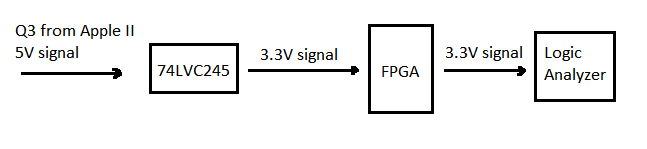
An important detail: The Q3 shown in this logic analyzer trace isn’t actually the FPGA’s Q3 input, because that’s on a PCB trace without any good place to attach a probe. The trace shows an FPGA output that’s been configured to simply propagate the Q3 input. That should be nearly the same thing, but not exactly identical. To complicate matters further, there’s also some level conversion happening. The Q3 supplied from the Apple IIgs is a 5V signal, and it passes through a 74LVC245 to create a 3.3V signal that’s connected to the FPGA. Behold my awesome diagram:
The previous Yellowstone prototype had a 390 ohm inline resistor between the Apple II’s Q3 signal and the 74LVC245. This is something I copied from the design of Apple’s Liron disk controller, although I don’t understand why it was there. None of the other disk controllers that I examined have a resistor on Q3, and I couldn’t find any documentation about a need for one, so I eliminated the resistor in this second generation prototype. Maybe that was a mistake, and is the reason why I’m seeing clock glitching now.
My hunch is there’s a different explanation. I suspect the glitching is caused by other problems on the board, rather than Q3 itself. Maybe there’s capacitive coupling between Q3 and another nearby signal trace. Or maybe my power and ground supplies are bouncing around whenever there’s a big spike in current, like when a bunch of chip outputs switch simultaneously from low to high, and that creates EM noise everywhere. Or maybe there’s some brief contention on the data bus that creates spikes and noise.
I tried playing around with the the FPGA input buffer settings for Q3, in an attempt to make the problem go away. I tried pull modes of KEEPER, DOWN, and NONE, and hysteresis settings of SMALL and LARGE. Nothing helped.
I’m not sure where to go next. I could try assembling a second board, to see if it’s just an assembly problem with this particular board rather than a general design issue. I could look for a way to get a logic analyzer probe directly on the actual Q3 input, which might require fancy soldering, and might also change the behavior. Or a probe on the 5V version of Q3, directly from the Apple II. I could try to patch a 390 ohm resistor onto the board, but it wouldn’t be clean and might create more clock problems than it solves. Or sprinkle some more capacitors around the board, or other analog magic.
Read 4 comments and join the conversationYellowstone Testing With Real Drives
I’m still testing the latest prototype of Yellowstone, my FPGA-based universal disk controller for Apple II computers. After a great deal of poking and prodding, the disk controller is now mostly working with all of the Floppy Emu’s disk emulation modes and with a variety of real Apple II drives. Hooray! But there’s still so much more work to do.
This is version 2.0 of Yellowstone, and it hasn’t exactly been a smooth experience getting it working. First I discovered a layout blunder, where I ran a signal trace right through a power via. After patching that with a razor and some wire, I struggled with mysterious signal glitching in a different section of the board. Some minor changes to the FPGA design made the glitching disappear, but I’m not convinced it won’t return later. Then I discovered a design flaw which means certain types of drives will create a short circuit when plugged into the card’s second drive connector. I’ll fix that in the next revision. Eventually I got the Yellowstone card working with a Floppy Emu, but real drives wouldn’t cooperate. That ultimately proved to be an issue with the width of the read pulses from the drives – they were too narrow to detect reliably. I adjusted the FPGA design to compensate, and now I’m finally in business.
Current status: I’ve had success with an Apple IIe plus Yellowstone booting from a Unidisk 3.5, an Apple 3.5 drive, an Apple Disk 5.25, and a Floppy Emu in its 3.5, 5.25, Unidisk 3.5, and Smartport hard disk emulation modes. The Disk II and Duo Disk should also work, though I haven’t yet tried them. But this is just the very beginning of testing, with a single Yellowstone card in slot 6 and a single disk drive. I haven’t tried writing to the disk, or formatting a disk, or daisy-chaining drives, or using the second drive connector, or anything in the Apple IIGS.
I tried connecting a Macintosh floppy drive pulled from a Quadra 605, and the Apple IIe wouldn’t even turn on. I think I shorted the power supply somehow. This was supposed to work. I’ll look at it more closely later.
Something is still funky with the Apple 3.5 Drive support. Two of the 3.5 inch floppies I tried will boot reliably, but one won’t. But the same three floppies work fine in the Unidisk 3.5. I haven’t yet tried to troubleshoot this one.
It also appears that the behavior changes depending on whether my JTAG programmer is connected to the card, and sometimes it doesn’t work if the programmer is connected. That’s concerning. In the past, I saw something similar with earlier prototypes. I’m not sure if the programmer is holding the FPGA in a reset state, or if it’s an analog problem with the card that’s affected by the presence of the programmer. Another mystery to investigate.
The Apple 3.5 drive and Apple 5.25 drive both sound noticeably different when used with Yellowstone as compared to an Apple standard disk controller. While I haven’t yet determined why, I think this is benign and is due to differences in exactly when and how the disk controller moves the drive head. But when you’re accustomed to disk drives having a certain characteristic sound during I/O, it’s a little disconcerting. The Apple 3.5 drive sounds frenetic, and the 5.25 drive’s familiar buzz-buzz-buzz startup noise is completely different. This latter one bothers me enough that I may try to change it, even if it’s not causing any problems.
Ruminations
It’s hard to believe, but the Yellowstone project will celebrate its fourth birthday this summer. I have to admit I’ve taken on a bigger challenge than was probably wise, and I’m struggling. For me, this stuff is hard – much harder than the Floppy Emu’s development. It’s difficult to maintain motivation when I keep running into one major problem after another, with the goal of “finished” always far away. And the domain of possible problems is huge. One day I’m troubleshooting some software incompatibility with GS/OS, the next day I need to become an expert in FPGA in-system programming, and the day after I’m chasing signal integrity problems in the analog domain. It’s tiring.
There’s still lots to do. All the problems I mentioned above must be examined and fixed. Then there’s a whopping huge amount of testing needed, with a dizzying number of permutations of computers, cards, slots, drives, daisy chain configurations, boot priorities, and software disks. That’s practically guaranteed to turn up more thorny problems that will be difficult to solve. And then I still need to build solutions for in-system reprogramming of the FPGA by end users, and for fast and thorough automated testing during manufacturing. I have some plans for how to handle those, but haven’t yet started any work.
I’m hopeful that while the Yellowstone project isn’t yet “almost done”, it’s at least close to the point where the finish line is visible. I really want to wrap this up and get it out the door.
Read 3 comments and join the conversationTesting Yellowstone 2.0
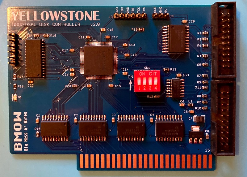
I’ve finished assembling the first prototype board of Yellowstone 2.0, my FPGA-based universal disk controller for Apple II computers. I used a syringe to dispense solder paste onto the pads, and baked the board on a hot plate with the surface mount components, before manually soldering all the through-hole components. It took about 1.5 hours to assemble, so it’s not something I’d want to do by hand very often. But for a one-off prototype it’s OK.
The board doesn’t work. After lots of puzzling and scratching my head, I determined that the data bus signal D5 is always stuck at 1. After another hour or two of puzzling, I discovered why. What’s wrong with this picture?
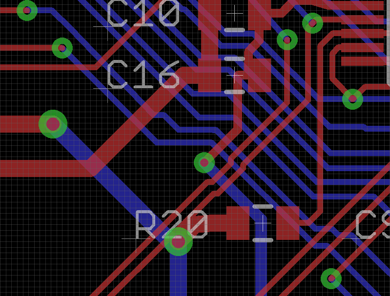
The image shows the traces and components on a small section of the Yellowstone 2.0 board. There’s a signal trace going directly through an unrelated power supply via under the R20 text. That signal trace is D5, so D5 is directly connected to the 3.3 volt supply. Arghh! How did I make that mistake? Why didn’t the layout software’s design rule checker warn me about the overlapping trace? When I rerun the DRC, it does warn me, so it’s not the software’s fault. I must have moved that trace just before I finalized the board layout, and forgotten to rerun the DRC. That’s an expensive mistake.
I can move the overlapping signal trace out of the way and get some new PCBs made, but that will take a few weeks. Meanwhile, can I fix this board somehow, so I can continue testing it? Usually I can fix mistakes like these by cutting a signal track with a razor, and soldering narrow gauge wire to replace the severed track. But here there’s not much room to work with for cutting. For most of its length, the problematic signal trace is only a few mils away from another signal trace, and my hand-cutting skills aren’t that precise. I also need to cut the track twice: once above the via overlap, and a second time below it, and then join them with wire. I think I can probably do it, but it’ll be tricky.
Read 7 comments and join the conversationApple II Binary Files and FPGA Reprogramming
I’m seeking help from all the Apple II programming gurus, with what may be an obvious question. During the development of the Yellowstone FPGA-based disk controller, I’ve written several times about my goal of providing a way for users to reprogram the FPGA without needing special hardware, in case there are bug fixes or feature improvements after the initial Yellowstone release. From a hardware standpoint, I think I’ve found a way to do this from the Apple II itself, by bit-banging SPI using some address lines and the slot’s /DEVSEL input signal. But from an Apple II software standpoint, I’m embarrassed to admit I don’t know what I’m doing.
I’d imagined something like this: a BASIC program asks the user what slot the Yellowstone card is installed in. It uses this to determine what Apple II address range will trigger the slot’s /DEVSEL. Then it reads binary data from a separate firmware file, maybe 1K at a time, and transmits it to the Yellowstone card via SPI using a carefully-crafted sequence of POKE statements. Or perhaps some helper assembly language routine instead of POKEs, for speed.
But as far as I can tell, Applesoft BASIC with DOS3.3 or ProDOS has no facility for reading binary files. Can that possibly be true? I fear I’m missing something obvious. Can I BLOAD a binary file from within a running BASIC program? How do I know what address is safe to load it at? Should I try storing the firmware in a zillion DATA statements in the BASIC program? I’m not sure it will all fit in the Apple II’s memory at once.
If I want to craft a small helper routine in assembly, to use within the BASIC program, what’s the best way to do that? I could encode it as DATA statements, but I think I’d need to copy it elsewhere before I could run it, and once again I’m unsure what address range would be safe to use.
There must be some example programs that already do something like this, but I’m drawing a blank.
Read 23 comments and join the conversationYellowstone 2.0 PCB
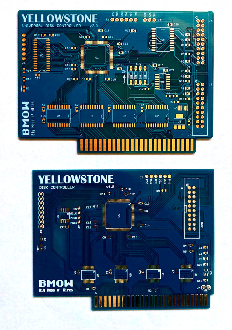
The Yellowstone version 2.0 PCBs are here! They sure look shiny. I wonder if they work.
This is the second generation of my FPGA-based disk controller design for the Apple II. In comparison to the version 1.0 PCB, you can see there’s more going on. While it’s nothing in comparison to any professionally-designed device, this will be the most complex thing I’ve ever designed or assembled.
Off to the Fab!
The Yellowstone 2.0 disk controller PCB has been sent to the fab. Now we wait. It took longer than I planned to finish it, first because I wasted a couple of days trying to shrink the board by 7 mm, then because I was obsessing over tiny layout tweaks. Now I can breathe a sigh of relief… except for the bad news. And the problem. And the other bad news.
Bad news #1 isn’t really a surprise. Thanks to the global IC shortage, the prices of components have increased. When I compare the IC prices from 2017’s Yellowstone 1.0 bill of materials to today’s prices, they’re up anywhere from 15 to 300 percent. Doh! I’m hoping this won’t affect the retail price too much, since the cost of materials is only one element of the total, along with cost of assembly, programming and testing, parts shipping, and general business costs like order fulfillment and customer support and other overhead.
The second problem is also cost-related. The twin DB-19 female adapters and cables for connecting the two disk drives are going to be more expensive than I’d like. The raw parts cost for a Yellowstone board with two DB-19F adapter cables is like 60 percent more than just the Yellowstone board alone! How can that be? Mechanical parts like connectors and cables just seem to be inexplicably expensive compared to most ICs except the FPGA. The worst offender is the DB-19 female, which isn’t manufactured anymore and is only available as new-old-stock from surplus suppliers.
As a result, I’m seriously considering selling Yellowstone in two versions: one that’s the board alone, and another that’s the board plus DB-19F adapter cables. With the board alone you can attach Floppy Emus, or Disk II drives, or internal Macintosh drives, or anything else with a ribbon cable and rectangular connector. But you’ll need DB-19F adapter cables if you want to connect drives like the Apple 3.5 or Unidisk.
Bad news #2 is my biggest concern now. The supply of the FPGA chip that I selected has shrunk dramatically in just a few weeks. I assume this is also due to the global IC shortage. It’s close to the point where I wouldn’t be able to manufacture any boards even if I wanted to. Only a few weeks ago, several different suppliers each had thousands of parts available, but as of today only a few hundred remain. I’m strongly considering buying them all right now, even though I don’t need them yet and the board design isn’t even finalized, just so I’ll have something on hand to do at least an initial run of manufacturing.
Read 3 comments and join the conversation