

Archive for the '68 Katy' Category
The Vintage Computer Festival is Almost Here!
Vintage Computer Festival West XI is happening next weekend, August 6-7 at the Computer History Museum in Mountain View, California. I’m belatedly dusting off the hardware for my exhibit and preparing the demos and signage. Anybody have a trade show style backdrop they’d like to lend me? 🙂
I’ll be exhibiting three of my hand-made computer creations, each of which has gone through some modifications for the show:
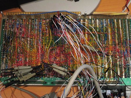
BMOW 1 – My original custom-made CPU and computer that kicked off this blog and my journey into hobby electronics. BMOW 1 is an 8-bit CPU, implemented with 7400-series TTL discrete logic and a few PALs. Built around this is peripheral hardware for I/O, sound, and video. The end result is a custom creation that’s vaguely similar to an Apple II in its performance and capabilities. And it’s all hand wire-wrapped, with thousands of individual wires.
New for VCF West, I’ve cut a porthole in the bottom of the case and added interior case lighting, to showcase the glorious mess of wires inside. I was nervous I’d break something while removing and replacing all the parts in the case, but BMOW survived and is still running strong.

68 Katy – A 68000-powered single-board Linux system that began life as “Linux on a breadboard”. It’s a super-minimal Linux system containing only a 68K family CPU, 512K ROM, and 512K RAM. I began with a 16 year old Linux distro and hacked it to support this hardware and its tiny memory size. The original version was literally built on a breadboard, though the current version is now a PCB with a serial port for I/O.
During testing for the VCF show, I found that 68 Katy was no longer running reliably. I’d previously overclocked the 8 MHz-rated 68008 CPU to 12 MHz. Restoring an 8 MHz oscillator seemed to fix the problems – for now.
Nibbler – Another custom-made CPU and computer with a 4-bit (nibble) architecture. Designed to be simple to build and easy to understand, Nibbler’s CPU core consists of just 13 discrete 7400-series logic chips – individual counters, registers, buffers, and gates. To complete the machine, it adds a few ROMs and an SRAM, as well as pushbuttons, an audio speaker, and a text display. With a 4-bit CPU and 4K of memory you might think Nibbler couldn’t do anything much more interesting than blink an LED, but it boasts some nice games and demos. Like BMOW 1, it’s all hand wire-wrapped.
Nibbler will see a significant change for the VCF show, time permitting. The original design uses a 4K ROM for storing the program – when you want to run a different program, you need to replace the ROM. I plan to substitute a 16K ROM with a DIP switch to control the highest two address lines, so I can select between four different stored programs without resorting to ROM swapping.
Antique and Custom Computers Galore
Beyond the BMOW stuff, the other exhibits planned for VCF West XI look great! They include Eric Schlaepfer’s MonSter 6502, Bill Buzbee’s Magic-1, vintage DEC and Data General systems, IBM mainframes, Amigas, TRS-80s, S-100 hardware, and much more. Check out the full list here.
The show hours are 9:30-6:00 on Saturday the 6th and 9:00-5:30 on Sunday the 7th. Do you plan to attend? Leave a comment below, and I’ll keep an eye out for you!
Read 1 comment and join the conversationMake Your Own Katy
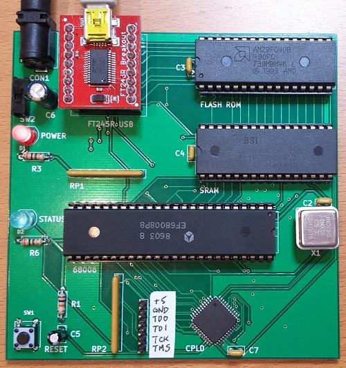
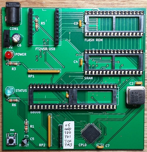
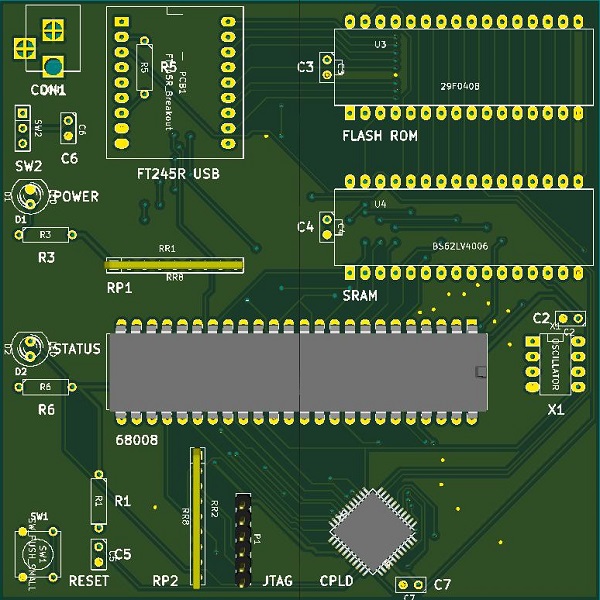
If you’re crazy enough to want to build your own 68 Katy, I’d like to help you do it. The PCB version is the easiest way to get started. Compared with the breadboard version, it replaces all of the glue logic, timers, and other miscellaneous components with a single CPLD. The number of status LEDs is also reduced from eight to one, and there’s a small change to the serial status address mapping. Otherwise it’s functionally identical to the original breadboard prototype. Get a PCB, solder the components, burn the ROM, and you’ll be in business.
Assembling the PCB requires soldering one surface mount component, the 44 pin CPLD in TQFP package. It can be soldered with a standard iron using the drag soldering method (my preference), with hot air, or with a toaster oven reflow. The rest of the components are easy through-hole parts.
You’ll need an EPROM burner to program the initial flash ROM data, as well as a JTAG programmer for the CPLD. I used a Bus Pirate with the XSVF player firmware to program the CPLD.
Note that the PCB and breadboard versions of 68 Katy are not binary compatible, due to a small difference in their memory maps. If you’re building the PCB version, be sure to use the files linked here, and not the breadboard version files.
PCB Version: Parts List
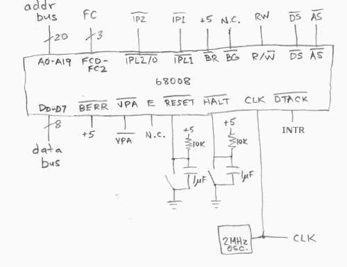
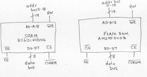
- Motorola 68008 CPU, 8 MHz, 48-pin DIP package
- AM29F040B or SST39SF040 4 megabit Flash ROM
- BS62LV4006PIP55 4 megabit SRAM, or compatible substitute
- Xilinx XC9536 CPLD – not XC9536XL
- Sparkfun FT245RL USB to FIFO breakout board
- 12 MHz metal can oscillator
- bypass capacitors, resistors, LEDs, buttons, switches, sockets, etc. – complete parts list
PCB Version: Files
- schematic and board layout – Board definition in KiCad format
- Gerber files – For getting a copy of the PCB made at a fab like Seeed Studio
- CPLD source – Xilinx ISE project and Verilog source code for the CPLD
- 68katy.xsvf – JTAG configuration file for the CPLD
- monitor.asm – My ROM-based monitor/bootloader program. I used Easy 68K to assemble it.
- monitor-plus-linux-pcb.bin – This is the final binary image I programmed into the flash ROM, containing the monitor/bootloader program with the uClinux kernel concatenated to it beginning at address $003000
- virtualboxes.org Ubuntu machine – For Linux cross-development, I used Ubuntu 12.04 32-bit running as a virtual machine under Virtual Box. Don’t use the 64-bit version, or the 68K toolchain won’t work. You can use this pre-configured Ubuntu Virtual Box machine image. Username “ubuntu”, password “reverse”
- uClinux-dist-20040218 – I started from the February 18, 2004 release of uClinux. This is the unmodified version.
uClinux-20040218-pcb.tar.gz – This is my modified version of uClinux. It includes code for kernels 2.0, 2.4, and 2.6, but I only ported kernel 2.0 for 68 Katy. Search the code for “68KATY” to find my changes. - m68k-elf-tools-20030314 – You’ll need a 68K cross compiler and other tools in order to build the uClinux source code. I used m68k toolchain 20030314. It’s supposed to be a self-extracting shell script, but that didn’t work for me. I had to extract it manually, like this:
user@ubuntu$ tail -n +43 m68k-elf-tools-20030314.sh | gunzip > tools.tar

user@ubuntu$ tar xvf tools.tar
Startup
Assemble the PCB. Attach a regulated 5V power supply, and turn on the power switch. Use the Bus Pirate or another JTAG programmer to program 68katy.xsvf to the CPLD – the board must be powered when you do this, but components other than the CPLD don’t necessarily need to be present yet.
Use an EPROM burner to program monitor-plus-linux-pcb.bin to the flash ROM, then place the ROM chip in the board’s socket. Place the CPU and RAM in their sockets as well.
Attach a USB cable to the FT245RL module, and plug it into your computer. The FT245RL module doesn’t need to be connected to the 68 Katy board yet – it’s powered by the USB cable. If necessary, install the FTDI virtual serial port driver software for your computer. When complete, your should see a new virtual serial port like COM4. Now place the FT245RL module in its socket on the 68 Katy board.
Turn on the 68 Katy board. Use terminal software like Tera Term to open the serial port where the FT245RL is connected. The serial port speed and parity settings actually don’t matter, although choosing a faster speed will result in faster file transfer times when sending updates to the board.
Press the RESET button on the 68 Katy board. If everything is working, you should see the monitor prompt zBug(ROM) for 68Katy (press ? for help). Press ? to see a list of available commands. The monitor can load Motorola S-record files, view or disassemble memory, and many other useful things. The uClinux image is stored in the flash ROM beginning at address 003000 hex. To start Linux, from the monitor prompt type j 003000.
Using the provided source code, you can modify the monitor program, the uClinux filesystem contents, or the uClinux kernel. Use a hex editor or other tool to concatenate the uClinux image file 68katy.rom to the monitor program monitor.bin. The combined result must be no larger than 480K. Note that 68katy.rom itself is a concatenation of the uClinux kernel code kernel.text, kernel initialized data kernel.data, and the read-only Linux filesystem image romfs.img. To update the flash ROM with the new monitor or uClinux, from the monitor prompt type u, then use the terminal software’s file transfer option to download the concatenated file. If using Tera Term, make sure to select the option to send the file in binary format, not text.
Have fun!
Read 23 comments and join the conversation68 Katy PCB Style
The 68 Katy PCB version is working! Mostly! I’ve had the parts and PCB on hand for a while, but only recently got around to assembling and testing the thing. Now instead of a breadboard that runs uClinux slowly, I’ve got a 10 x 10 cm PCB that runs uClinux slowly. Ah, the sweet taste of success.
Assembly
The assembly process went smoothly, even though I forgot to label some important items on the silkscreen like the JTAG pins. Revision 2 can fix that. The only real soldering challenge was the Xilinx CPLD, a 44-pin SMD chip. The PCB footprint for the CPLD wasn’t the best, as the pads were barely any larger than the pins themselves, making it somewhat difficult to solder with an iron. But thanks to my experience hand-soldering hundreds of similar chips with Floppy Emu, I was able to use a drag soldering technique to get the CPLD down with only minor rework required. The rest of the through-hole components were quick to solder, and I finished the board off with a fancy blue status LED.
Since I don’t own a Xilinx programmer, I used a Bus Pirate to program the CPLD. The process isn’t too bad for occasional or emergency use. Using the Xilinx IDE software, you can create a .xsvf programming file for your design and the target chip type. Then you flash a special XSVF player firmware onto the Bus Pirate, connect the BP’s pins to the JTAG header on your board, and finally run a Windows utility to program the .xsvf file to the chip. I was stuck for a while at the point of flashing the alternate firmware to the Bus Pirate, since I’d forgotten that you must manually invoke the bootloader before updating the BP’s firmware. Once I figured that out, the actual CPLD programming was quick.
Boot Up
I pulled the 68008 CPU, RAM, and ROM from the breadboard, stuffed them into the sockets on the new PCB, and confidently flipped the power switch. Oh my eyes, that blue LED was blinding! Who chose that thing?? I tried to take a photo of it, but it’s so overwhelming that it just looks like a white dot on a dim background. Next time I’ll stick with red, but for now I think I’ll need to wear sunglasses when using this thing. 🙂
Of course the board didn’t work. When powered on, it appeared to do nothing at all. I poked and prodded for a while with a logic probe, and all the signals seemed to be behaving normally. I don’t know why I always fall back to the logic probe, when I’ve got two logic analyzers and an oscilloscope that would give me much better information, but somehow those tools always feel like too much hassle to get out and set up.
After a few minutes I remembered that I’d made a small change to the address map for the PCB version, so the software for the breadboard version won’t be directly compatible. In order to save CPLD pins and board traces, I changed the way the RDF and TXE status bits are read from the FT245 USB FIFO. In the breadboard version, these status bits appear in different bit positions at a single memory address. But in the PCB version, they appear in bit 0 of two different memory addresses. Both my monitor program and my uClinux FT245 driver needed to be modified to reflect this change.
BREADBOARD 68 KATY               PCB 68 KATY
00000 - 77FFF : ROM              00000 - 77FFF : ROM
78000 - 79FFF : serial in        78000 - 79FFF : serial in
7A000 - 7BFFF : serial out       7A000 - 7BFFF : serial out
7C000 - 7DFFF : serial status    7C000 - 7CFFF : serial status RDF
                                 7D000 - 7DFFF : serial status TXE
7E000 - 7FFFF : LED register     7E000 - 7FFFF : LED register
80000 - FFFFF : RAM              80000 - FFFFF : RAM
Once I made that fix, the board was up and running! I played with the monitor program, booted uClinux, and played Adventure. Everything seemed solid.
“Mostly”
The breadboard version of 68 Katy ran at 2 MHz, and didn’t work at higher speeds. I initially tried the PCB version at 2 MHz as well, and everything was great. But when I tried faster speeds like 6 or 8 MHz, it didn’t work at all — it just did nothing, or spewed endless garbage characters. I was disappointed, because I’d hoped the cleaner signals on the PCB vs the breadboard would enable the computer to run at higher speeds.
But wait! After a lot of fiddling around, I discovered that the PCB version of 68 Katy had no trouble running at higher speeds, it just had trouble resetting at higher speeds. If I moved my hand around the CPU while repeatedly pressing the reset button, eventually it would work and the monitor prompt would appear. After that everything was fine, and I could use the monitor program without trouble, or boot into uClinux and play Adventure or run vi. I successfully tested the hardware at 2, 4, 6, and 8 MHz. As long as I could get it to reset cleanly, then it ran flawlessly.
So what’s going on? By touching different CPU pins with my finger, I think I’ve narrowed the problem down to either the /IPL2 interrupt pin, the /RESET and /HALT pins, or the reset button debounce circuit. /IPL2 is the 100 Hz timer interrupt, and it seems like maybe the CPU is immediately hitting an interrupt the instant it comes out of the reset state. Since the interrupt vectors haven’t been initialized yet, it crashes. That does’t fit what I know about the 68008, though – the datasheet says interrupts will be disabled after a CPU reset. Maybe there’s a bug in my monitor program that enables interrupts before the vectors are initialized, but I double-checked and didn’t see anything like that. Anyway, it’s the same monitor program that worked fine on the breadboard.
A more likely explanation is a problem with the reset signal itself. The board has a pushbutton with an RC debounce circuit, with the pushbutton signal connected to a CPLD input. The CPLD uses that to generate the /RESET and /HALT signals for the CPU, which are a little bit strange in the 68000 family. In order to reset the CPU, both /RESET and /HALT should be pulled low. But to exit the reset state, /RESET and /HALT should be allowed to float, and pulled high with an external pull-up resistor. That’s because those signals are actually bidirectional, and are sometimes pulled low by the CPU itself. On the 68 Katy PCB, both signals have independent 10K pull-ups to 5 volts. The CPLD code looks like this:
assign _reset = button ? 1'bZ : 0;
assign _halt = button ? 1'bZ : 0;
Maybe /RESET and /HALT aren’t being deasserted at the same time? Or maybe the rising edge on the pushbutton signal is too slow, and the signal lingers too long in the forbidden voltage zone between logical 0 and 1, causing problems? Indeed, if I monkey with the pushbutton circuit to reduce the RC time constant, it seems to help somewhat, but maybe that’s a red herring.
Maybe the action of the charging/discharging capacitor in the pushbutton circuit is causing some electrical noise that messes up the CPU?
The question is why any of these problems would be worse at higher clock speeds. At 2 MHz, the board runs fine. At 4 MHz, the board fails to reset properly about half the time. At 6 MHz, the board virtually never resets properly, unless I run my finger back and forth across the CPU pins while repeatedly pressing the reset button. 8 MHz behaves even worse than 6 MHz. This must be a clue…
Read 12 comments and join the conversation68 Katy PCB, Dead on Arrival
A few weeks ago I designed a PCB for 68 Katy, and yesterday the boards arrived in the mail. While I had originally imagined the PCB version of 68 Katy would include all sorts of new and exciting features, what I designed was almost a straight copy of the breadboard version of 68 Katy. I knew I couldn’t keep that breadboard prototype intact forever, because sooner or later I’d need the breadboard for something else, or my cat would jump on the desk and knock something loose. The PCB became mainly a way to preserve the existing 68 Katy design in a more permanent form. The only significant change from the breadboard version was the replacement of the PAL and all the 7400 glue logic with a single Xilinx XC9572XL CPLD.
When the PCB arrived, I took one look at it and realized it wouldn’t work. Check out the rendered image above, and see if you can guess why. Hint: I forgot to include a component that wasn’t needed in the breadboard version, but is needed here.
This is a 5V design, intended to be powered by an externally regulated 5V supply. The CPLD that I selected has 5V tolerant I/O, but it needs a 3.3V supply voltage. So where’s the 3.3V power source? Oops, there isn’t one. I connected the CPLD supply pins to 5V, which will toast the chip.
I can add a 3.3V regulator to the board, and fix up the few traces that are affected, but I’m annoyed with myself for wasting three weeks and $40 to discover a problem I could have caught just by looking at my schematic. I wonder what other errors I made?
This PCB was made with KiCad, and it was my first time using that program to create a real board. Looking at the finished PCB, it appears that many of the footprints I used have what I’d consider to be abnormally small plated rings around the drill holes for through-hole components. They should still work, but it will be more difficult to hand-solder the components and get a good solder contact with the board, so I’ll probably resize all those too when I make the board revisions.
I wish there were more things I could test on this PCB, to help catch other hidden problems, but unfortunately it will be completely non-functional without a CPLD. I think my goof with the power supply for the CPLD is beyond anything I can fix with some cutting and jumper wires, since it needs a 3.3V supply, but there isn’t one anywhere on the board.
Read 19 comments and join the conversation68 Katy Schematics and Parts List
A number of people asked for a parts list and schematic for 68 Katy, so they could build their own version. Here it is! Please let me know if you find any errors.
Parts List
- Motorola 68008 CPU, 8 MHz, 48-pin DIP package
- AM29F040B 4 megabit Flash ROM
- BS62LV4006PIP55 4 megabit SRAM
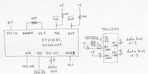
- Sparkfun FT245RL USB to FIFO breakout board
- 2 MHz metal can oscillator
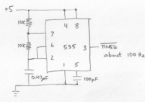
- NE555P timer, 8-pin DIP package
- 74LS139 decoder
- 74LS377 8-bit register
- 74LS244 8-bit tri-state driver
- 74LS00 quad NAND
- 74LS08 quad AND
- 74LS32 quad OR
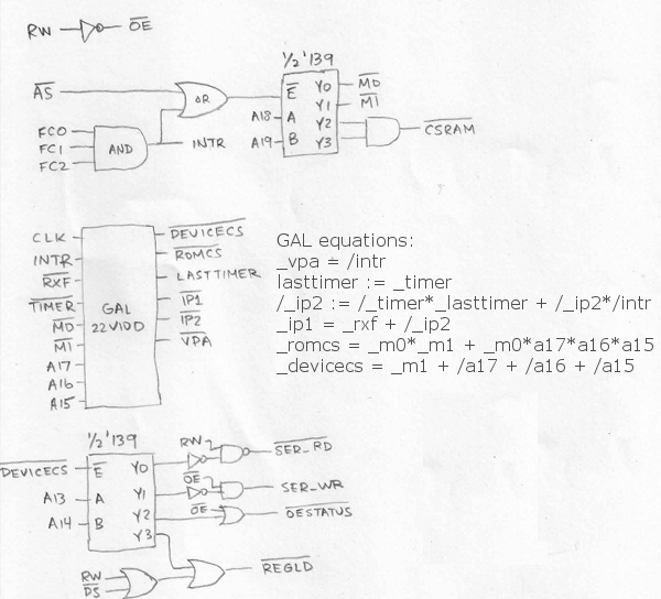
- Lattice GAL22V10D logic array
- bypass capacitors, resistors, LEDs, buttons, etc.
The GAL was used to replace some of the glue logic that would otherwise have required more NAND’s, OR’s, flip-flops, etc. If you’re building your own version of 68 Katy, you don’t necessarily need the GAL. Just replace it with the equivalent 7400-series basic logic gates.
Memory Map
00000 - 77FFF : ROM
78000 - 79FFF : serial in
7A000 - 7BFFF : serial out
7C000 - 7DFFF : serial status
7E000 - 7FFFF : LED register
80000 - FFFFF : RAM
CPU
RAM and ROM
Control Logic
555 Timer for Scheduler
USB Serial FIFO
LED Display
68 Katy – 68000 Linux on a Solderless Breadboard
What does it take to build a little 68000-based protoboard computer, and get it running Linux? In my case, about three weeks of spare time, plenty of coffee, and a strong dose of stubborness. After banging my head against the wall with problems ranging from the inductance of pushbutton switches to memory leaks in the C standard library, it finally works! I’ve built several other DIY computer systems before, but never took their software beyond simple assembly language programs. Having a full-fledged multitasking OS running on this ugly pile of chips and wires is a thrill, and opens up all kinds of interesting new possibilities. I’ve named this plucky little machine 68 Katy.
Hardware

Here’s a look at the final version of the hardware. It took about a week to assemble and wire up all the parts on a solderless breadboard. The heart of the system is a Motorola 68008 CPU, a low-cost variant of the more common 68000, with fewer address pins and an 8-bit data bus. The CPU has 20 address pins, allowing for 1 MB of total address space. It’s paired with a 512K 8-bit SRAM, and a 512K Flash ROM (of which 480K is addressable – the remaining 32K is memory-mapped I/O devices).
The standard 68000 CPU has a 16-bit data bus, so it normally requires at least two 8-bit RAM chips and two 8-bit ROM chips. The 68008 requires fewer memory chips thanks to its 8-bit data bus, but the trade-off is that memory bandwidth is only half that of the 68000. Neither chip has any on-board cache, so half the memory bandwidth leads to roughly half the performance. My 68008 runs at 2 MHz (it was unstable when tested at 4 MHz), providing similar performance to a 1 MHz 68000. That’s pretty slow, even in comparison to 68000 systems from the early 1980’s, which were typically 8 MHz or faster.
An FT245 USB-to-FIFO module provides a communication link to another computer. On the external PC, it appears as a virtual serial port. Windows Hyperterm or another similar terminal program can be used to communicate with it, like an old VT100 terminal. On the 68 Katy side, the FT245 appears as a byte-wide I/O register mapped into the CPU’s address space. Reading from its address fetches the next incoming byte from the PC, and writing to the address sends a byte out to the PC. The FT245 has an internal 256-byte buffer, which helps smooth out the communication. When there’s an incoming byte waiting in the buffer, it triggers a CPU interrupt.
A 555 timer provides the only other interrupt source, generating a regular series of CPU interrupts at roughly 100 Hz. The initial version of the hardware had no timer interrupt, but I later discovered it was essential in order to get Linux working correctly.
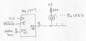
The protoboard has eight LEDs for debugging, which are driven from a memory-mapped 74LS377 register. The rest of the protoboard is filled with assorted 7400 series parts and one PAL, which are used for address decoding, interrupt arbitration, and other basic glue logic.
Schematics? Forget it. Everything was built incrementally, one wire at a time, while staring at chip datasheets. It’s an organic creation.
Software
Once the hardware build was done, I began writing some simple test programs in 68K assembly language. Wichit Sirichote’s zBug monitor provided a good starting point for my own ROM-based monitor/bootloader. Using the monitor program, I was able to load other programs in binary or Motorola S-record format over the FT245 link, store them in RAM, and execute them. I was even able to get Lee Davison’s ehBASIC for 68000 working, which provided a few hours of fun.
One feature I could have added to the monitor program, but didn’t, was the ability to reprogram the Flash ROM. The ROM chip has a read/write input pin just like an SRAM, but writing to the Flash ROM is more complicated. The CPU needs to first write a magic sequence of bytes in order to unlock the ROM. Then it needs to write more magic bytes to tell the ROM which blocks to erase, followed by the new bytes to be written. Finally, it must poll the output of the ROM to learn when the erase and reprogram sequence is complete.
The monitor program could have updated itself, or any other data stored in ROM, by copying itself to RAM, then running from RAM while saving new data to Flash ROM. But I was lazy and never implemented that feature, so I had to physically pull the ROM chip from the protoboard and place it in an external EPROM programmer whenever I made a change – about 100 times over the course of the project. Ugh.
Linux
Inspired by a similar project, I decided that a simple monitor program and BASIC weren’t interesting enough, and I needed to run Linux on this hardware. It sounded interesting and exciting, but I really had no idea where to begin. I had plenty of experience as a Linux user (as well as other UNIX versions), but I knew nothing about how the kernel worked, or how to build it from source code, or to port it to new hardware. So the real adventure began there.
The first challenge was to learn how to build a Linux image for an existing machine. It seemed simple enough in theory – just download the source code from kernel.org or some other distribution tree, and compile it. Reality was more complicated, and there were many details that confused me, and build problems I was powerless to solve. It wasn’t easy, and I discussed the process in much more detail in this earlier post.
I chose to use uClinux, a Linux distribution designed for microcontrollers and other low-end hardware, particularly CPUs without an MMU and that can’t support virtual memory. Then I chose a very old version of uClinux, based on kernel 2.0.39, that dates all the way back to 2001! I configured it to disable nearly every single optional feature, including all networking support. This ancient code was my best hope for getting a Linux that would actually run in 512K of ROM and 512K of RAM.
Starting with the uClinux configuration for another 68000-based system, I updated the code to reflect the 68 Katy memory map, changed the system initialization code, and added a driver for the FT245. Describing those steps makes them sound simple, and they might have been for someone more experienced with Linux, but for me it was a challenge just to identify which files and functions needed to modified. Google wasn’t very helpful, since I was working with such an old version of the kernel, and the resources I found on building/porting Linux mostly weren’t applicable. I primarily relied on the Linux grep command to search through the thousands of kernel source files for strings of interest, then stared at the code until I could understand how it worked.
After about a week, I had something I was ready to test. And it worked, at least a little bit! It showed the first few lines of kernel output, but hung at “calibrating delay loop”. Aha, I needed a timer interrupt. Of course! I added a 555 timer and some extra interrupt logic, and was ready to try again.
The second attempt got further into the boot process, but failed to mount the memory-resident root filesystem. I was stumped for a while. After looking more carefully, I discovered that my linker script was mapping the root filesystem and BSS to the same address in RAM, and the earily initialization code was overwriting the filesystem with zeroes. And more fundamentally, I discovered that it wasn’t possible to fit all of Linux in 512K RAM, including the kernel code, static data, root filesystem, and dynamically allocated memory. Something had to be moved to ROM, or it was never going to work.
In the third attempt, I moved the root filesystem image to ROM, freeing up about 150K of RAM. And this kind of, almost worked! It booted, mounted the filesystem, and seemed to be working OK, but then suddenly it would land back at the monitor program prompt. Huh? I eventually tracked this one to the FT245 driver I’d written. I only implemented the minimal set of required driver functions, and the other optional functions were NULL entries in a function table somewhere. One of the functions I thought was optional proved to be required. When the kernel called it, it used a NULL function pointer, causing a jump to address 0, restarting my monitor program.
The fourth attempt was better. It spawned the init process, and ran the startup script, but died with out-of-memory errors before it completed. At the time, 68 Katy’s memory map was 256K ROM, 256K I/O devices, and 512K RAM. By shrinking the I/O space to 32K, I was able to increase the usable ROM to 480K, providing enough space to store the root filesystem image and the kernel code itself! This freed up another 251K of RAM.
The fifth attempt actually booted to a shell prompt! Now it was executing the kernel code directly from ROM. I was able to run a few commands, like ls and cat, but then the system would run out of memory and die. As I investigated, it looked like memory allocated from malloc() and do_mmap() was never beeing freed. Was this some kind of free list allocator I didn’t understand? No. It turns out I’d made a typo in a function called is_in_rom(), adding too many zeroes, causing the memory allocator to think all addresses were in ROM and so didn’t need to be freed. Then after fixing that, I discovered a small memory leak in the C library setenv() function. I never did solve that one, but instead just modified the programs that used it to avoid calling it.
My debugging method was primitive: lots of printk and printf statements sprinkled everywhere. Then pull the ROM chip, reprogram it in an external EPROM programmer, replace it in the protoboard, and try again.
The sixth attempt finally worked. Two weeks after beginning my experiments with Linux, I had a working system! Here’s a screenshot of the boot sequence:
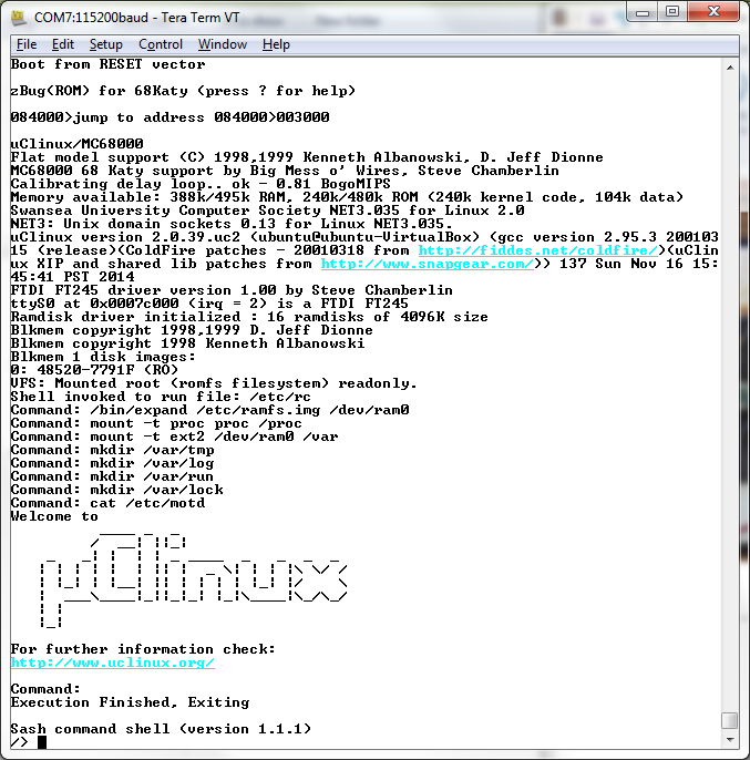
Watch the video for more details. I’m using a shell called sash, which has a few dozen common shell commands (like ls and cat) built directly into it. The root filesystem in ROM is read-only, and a small read-write filesystem is created in a RAM disk. The system supports multitasking, so it can run an LED blinker program in the background while still working in the Linux shell. It even has vi, and Colossal Cave Adventure!
It was an interesting journey. The Linux kernel still seems big and unwiedly to me, but no longer seems so scary as it did initially. It’s just an especially big program, and most of its pieces aren’t too difficult to understand if you open up the relevant source files and start reading.
Memory Requirements
So how much memory does it require to run a super-minimal uClinux system, with an old 2.0 kernel? If you follow my example and put as much as possible in ROM, it needs about 343K of ROM and 312K of RAM, or just 628K of RAM if you’ve got a bootloader that can fill RAM from some external source. My 68 Katy system is slightly heavier than that due to including vi and Adventure, but not by much. Here’s the breakdown:
ROM
- kernel code and read-only data (.text and .rodata segments) – 251K
- kernel initialized static data (.data segment) – 27K
- root filesystem – 189K
RAM
- kernel static data (.data and .bss segments) – 84K
- kernel dynamic allocations during boot-up – 104K
- RAM disk – 64K
- init and shell process allocations – 58K
- stack and exception vectors – 2K
Problems
The kernel always measures the CPU at 0.81 bogomips, regardless of the clock crystal I use. The 555 timer interrupt is independent of the CPU clock, so with a faster clock the bogomips calculation should measure more executions of the busy loop per timer interrupt. I’m not sure why it doesn’t, but it means any real-time calculations will be off.
The display in vi acts weird. Some lines appear prefixed with a capital H, and stray Unicode characters appear here and there. At first I thought this was a hardware bug, and I’m still not certain it isn’t. But I think it’s probably an issue with the way my terminal program (Tera Term) handles the ANSI escape sequences sent by vi. I tried all the different terminal settings available in Tera Term, and also tried a different terminal program, all with the same result.
What’s Next?
This 68008 system on a protoboard was intended to be only an experiment and proof-of-concept for the real 68 Katy, which I had planned to build on a custom PCB with a full 68000 CPU, a CPLD for glue logic, more RAM, an SD card, and ethernet. But this experiment was perhaps a bit too successful, and now I’m wondering if it really makes sense to go to the effort of building the “real” system if it’s going to be essentially the same thing, only faster. Of course the SD card and ethernet will add some interesting new elements, so maybe it’s fine. I probably need to sleep on the question for a few days.
One way of adding more spice to the next iteration of 68 Katy would be to include video output, so it could directly drive a monitor instead of being controlled through a serial terminal. I’ve done that once before, with BMOW 1, which had VGA output. It mostly worked, although the arbitration for video memory between the display hardware and the CPU was clunky and produced visible display artifacts. To take things further, I could even aim for DVI or HDMI video output, since VGA is a slowly dying standard.
The smart move is probably to stick with my original plan. Lots of extra features are cool, but also have a way of killing a project. I’d rather have something with 10 features and that works, than something with 20 features that I never finished or that collapsed under the weight of its complexity. But until then, excuse me while I go play some more Colossal Cave…
Files
The source code for my 68 Katy port of uClinux is available for download, as well as the toolchain I used to build it, the monitor/bootloader source, and a preconfigured VirtualBox machine image of Ubuntu 12.04 to host it all. Grab the files here. Have fun!