

Archive for the 'Yellowstone' Category
4th Quarter Fumble
Whoops! I’ve discovered a basic flaw with the Yellowstone disk controller design: when an intelligent Smartport drive is connected in parallel with a 3.5 inch or 5.25 inch drive, the Smartport drive may be inadvertently enabled or reset as a side-effect of 3.5/5.25 inch disk activity. This isn’t just a mistake in my circuit, but a fundamental consequence of the way these drives work. I don’t know how I never realized it before. Just when I thought that Yellowstone development was nearly finished, here’s one last challenge.
This probably explains why there aren’t other Apple II drive controller cards that support intelligent Smartport drives and that have two parallel disk connectors, except for the long version of the UDC. It may also explain why Smartport support was dropped when the long UDC was redesigned into the short version.
Drive Enable Signals
When multiple drives are connected to a single controller, most of the I/O signals are shared between all of them. For Yellowstone and most other drive controllers that I’m familiar with, the common I/Os include the four PHASE control signals as well as all the read/write signals. Avoiding confusion and collisions on the shared signal lines requires a method of enabling one specific drive at a time. For 3.5 inch and 5.25 inch drives, simple /ENABLE and /EN3.5 signals are used to enable the desired drive. This works fine whether the drives are connected in series as a daisy-chain, or if they’re connected in parallel as Yellowstone does it.
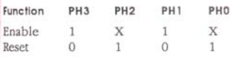
But intelligent Smartport drives work differently. The don’t have normal /ENABLE signals. Instead, they’re enabled when PHASE1 and PHASE3 are high and PHASE2 is low. They’re reset when PHASE1 and 3 are low and PHASE0 and 2 are high. Here’s the relevant table from the Apple IIgs firmware reference:
But 3.5 and 5.25 inch drives use the PHASE signals for other purposes, not for enabling, which creates a problem. For 5.25 inch drives, the PHASE signals directly control a stepper motor. For 3.5 inch drives, the PHASE signals select one of sixteen drive registers. If normal disk activity with one of these drives just happens to involve a PHASE combination that resets or enables an intelligent Smartport drive on Yellowstone’s other drive connector, major problems could occur.
So why doesn’t this problem also appear with Apple-branded drive controllers or with the built-in drive controller of the Apple IIgs? The other drive controllers either don’t support this combination of drive types, or else they use daisy-chaining. With daisy-chaining, there’s an opportunity for the earlier drives in the chain to modify the PHASE signals that are passed through to later drives, and that’s exactly why Apple requires daisy-chained drives to be connected in a specific order. 3.5 inch drives must appear before Smartport drives, because when a 3.5 inch drive is enabled, it forces low all the PHASE signals for later drives. This prevents any daisy-chained Smartport drives from being unintentionally enabled or reset.
A Hardware Fix
A proper fix for this problem would require separating some of the common PHASE signals, so there are independent signals for drive connector 1 and connector 2. Having independent versions of PHASE0 and PHASE1 should suffice, since forcing both of these low would be enough to prevent Smartport enables and resets on a specific drive connector. In theory, if the controller knows that it’s communicating with a 3.5 inch or 5.25 inch drive at connector A, it could force low PHASE0 and PHASE1 at connector B.
In practice this wouldn’t be easy to do now. There aren’t any free pins on the output buffer chips where new PHASE signals could be added, so I’d need to add an additional chip in a section of the board where the trace routing is already very crowded. I’d need to route the new traces, and find new FPGA pins, when I’m already running up against the limits of a 2-layer PCB and my journeyman layout skills, not to mention my dwindling patience.
Even if the necessary hardware were in place, the software might also be tricky. I need to think about it more, but the drive connector number where a drive is attached may not always be the same as the logical drive number. For example, a DuoDisk might have drive 1 and drive 2, but the whole DuoDisk unit is still attached to drive connector 1. This could make it more difficult to know which disk connector’s PHASE signals should be altered.
Maybe… It’s Actually OK?
You’re probably wondering how this obvious of a problem was never discovered before. It’s true, I’ve tested intelligent Smartport drives on Yellowstone side-by-side with other drives many times, and never experienced an obvious problem related to this. It wasn’t until earlier today that I happened to notice that a Floppy Emu in Unidisk 3.5 emulation mode (a type of Smartport mode) underwent 10 or more unexpected resets while booting GS/OS from a 3.5 inch drive. Even then, it still worked OK. Miraculously, it looks like the problematic PHASE combinations rarely or never occur in real life.
First let’s look at 5.25 inch drives, where the PHASE lines directly control a stepper motor. It would never make sense for a 5.25 inch drive to energize PHASE0 and PHASE2 at the same time, or PHASE1 and PHASE3, because they would pull the motor in opposite directions and cancel each other out. Yellowstone’s 5.25 inch drive control logic never does this. Since the Smartport enable and reset PHASE combinations both require opposite PHASE pairs to be simultaneously high, these combinations can never happen during 5.25 inch disk activity.
Next let’s look at how 3.5 inch drive activity might trigger a Smartport enable. This would require PHASE1 and PHASE3 high and PHASE2 low. But for 3.5 inch drives, PHASE3 is almost always low, meaning this is very unlikely to happen. PHASE3 only goes very briefly high when the computer writes to a drive register. Following this rabbit hole further down, the only valid combination of 3.5 inch drive register number and value that could trigger an unwanted Smartport enable is writing 0 to the MOTOR_ON register. But what happens then? The Smartport drive will think it’s enabled, and start listening for a command, but won’t see one. Then an instant later when the MOTOR_ON write is completed, the Smartport drive will become disabled again without ever doing anything. This shouldn’t cause any problems for either drive.
The final case to consider is 3.5 inch drive activity that might trigger a Smartport reset. This will occur if PHASE1 and 3 are low and PHASE0 and 2 are high. Digging through the 3.5 inch drive register numbers, these correspond to a pair of registers related to SuperDrive / MFM disk operation – registers that Yellowstone never uses. This PHASE combination could also theoretically occur for some register writes, but in practice none of the problematic register/value combinations are ever used.
As far as I can tell, the only way an unwanted Smartport reset could occur for Yellowstone is when a 3.5 inch drive’s PHASE0, PHASE1, and PHASE2 are transitioning from one set of values to another (remember that PHASE3 is always low except for a register write strobe). The PHASE signals change one at a time under CPU control, so it’s possible they might briefly land on the problematic combination even if the CPU isn’t intentionally aiming for it. This suggests that Floppy Emu’s Smartport-based emulation modes could check the amount of time that the PHASE signals are in the combination for a reset, and ignore it if it’s below a certain threshold. A real Smartport reset lasts about 80 ms, which is much longer than most other disk I/O signal activity. But real Smartport devices like the Unidisk 3.5 can’t be modified – they will either work with Yellowstone or they won’t.
Next Steps
Ideally this problem should be solved through hardware, but I really don’t want to reopen that box and start major new changes to the Yellowstone PCB. It would set back my efforts by weeks, or maybe months, and I don’t have the appetite for it.
It seems like poor practice to rely on a software-driven “it works anyway” argument, but… it does seem to work. Obviously I’ll need to test this a lot more. But if the problem never occurs in the real world of Apple drives and Yellowstone’s drive control firmware, then I won’t be motivated to redesign the hardware just to earn a merit badge in thoroughness.
Read 11 comments and join the conversationPCB 2.2, Board Tester, And One More Problem
Yellowstone PCB version 2.2 is ready to be sent for fabrication. This is the fourth and hopefully finally PCB version, coming after 1.0, 2.0, and 2.1. But I also thought 2.1 would be the final version, so my powers of prediction are questionable. Here’s what’s new in v2.2:
- Manual -12V Supply Control – I’ve struggled for a while over how to handle the -12V supply on pin 9, which is required for some drives, ignored by others, and causes problems for few. The -12V supply is now enabled by a pair of DIP switches, one for each drive, so the choice is left up to the user. In 99 percent of cases -12V should be ON and the user should never need to touch it. I’ve also added a PTC resettable fuse to each -12V supply connection, which will limit the current to about 30 mA if there’s a misconfiguration.
- /EN3.5 for Drive 2 – The previous version didn’t provide the /EN3.5 signal to Drive 2, since I didn’t think it was needed. That pin was always low (asserted), making 3.5 drives think they were selected, and other types of drives ignore the signal. This worked OK, but it confused the Apple 3.5 Drive A9M0106 into thinking it was connected to a Macintosh, causing it to disable the manual eject button. Version 2.2 resolves this.
- Return of the Disk II Mode Switch – Yellowstone can optionally behave as a vanilla Disk II Controller Card, for maximum compatibility with copy-protected software. PCB version 2.0 enabled this mode with a switch, version 2.1 eliminated the switch in favor of a keyboard enable method, version 2.2 supports both the switch and the keyboard enable.
- Recovery Programming Enable – Version 2.1 supported recovery mode, a method for in-system programming of the FPGA even if it was misprogrammed or erased. Version 2.2 moves the recovery mode enable from a jumper to a DIP switch, since I was already adding a DIP4 package for the other items just mentioned.
- External Programmer Recovery Mode – A Schottky diode was added between the FPGA’s /SPI.CS pin and Yellowstone’s +12V supply. Normally this diode is reverse biased and does nothing, but the forthcoming tester board will be able to dynamically change the +12V supply to 0. This will provide a second way to enable recovery programming mode during manufacturing of Yellowstone boards, avoiding the need to touch the DIP switches and the potential for setting or leaving the switches in the wrong positions.
Tester Board with Blue Pill Brains

I’ve continued sketching out plans for the tester board, as initially described in my previous post. I’ve decided to build the tester around an STM32 Blue Pill, not because the Blue Pill is the absolute best tool for the job, but because it’s an adequate tool and also a helpful gateway to learning more about STM32 development.
The tester board will need a large number of I/Os. After a few hours of sketching, I think a microcontroller with 32 GPIOs will be enough, combined with a pile of port expander hardware. Not coincidentally, 32 GPIOs is exactly the number provided by the Blue Pill. If I get partway through the tester board design and discover that I need an extra I/O pin or two, it could be awkward. It looks like the two serial debug pins can be repurposed as GPIO if you’re not using them, as well as the BOOT1 pin, so it could possibly stretch as far as 35 GPIOs.
The basic design is this: Eight microcontroller pins are used for output, and are connected to four ‘373 transparent latches, providing a total of 32 controllable outputs. Eight pins are used for input, and are connected to four ‘244 buffers, providing a total of 32 inputs. Eight pins are used for bidirectional data bus communication, and the final eight pins are SPI and control signals for the buffers and latches.
During the course of testing, some inputs may also need to be pulled low. A ‘156 decoder will be used for this. The ‘156 can pull low any one of its eight outputs, using a three-bit selection input and an enable input.
One half of a second ‘156 decoder will be used to enable the desired input buffer from among the four possible buffers. Since a buffer is always enabled, this only requires two bits for the selection input, instead of four individual enable signals. This cuts down the number of control signals required from the microcontroller.
The design and programming of the Yellowstone tester board will be a significant engineering challenge in its own right. The proposed approach will require the STM32 Blue Pill mounted on a board with ten other support chips, three connectors, and close to 100 signals. Writing the code to program the FPGA and run/analyze the test vectors will be interesting. Kudos to people who design test fixtures for a living – this stuff isn’t glamorous, but it’s important to get right.
One More Problem – GS/OS and Drive 2
Yellowstone still has many smaller bugs and issues, but as far as I know there’s only one remaining major problem. It’s not even a Yellowstone problem per se, but it affects Yellowstone negatively. The issue is that GS/OS will not boot from Drive 2. It starts to boot, but then early in the boot process it unexpectedly tries to switch to Drive 1, and fails with the error “Unable to load START.GS.OS file”. As far as I can tell, this is a software limitation with GS/OS and not anything that Yellowstone is doing wrong. It shows the same behavior if GS/OS is loading from a 3.5 inch drive or from a Smartport hard disk.
Most other 3.5 inch and Smartport disk controllers will not even try to boot from Drive 2, which may explain why this GS/OS limitation isn’t well-known.
This behavior is similar to some 5.25 inch disk software that refuses to boot from Drive 2, even though there’s no technical reason for it. Such software is written with the assumption that the disk is in Drive 1, and fails if that’s not true. Bad programmer, no biscuit!
You may wonder why this is important. Can’t people just boot GS/OS from Drive 1? Yes they can, but that raises a new problem.
People who run GS/OS are probably booting it from some type of hard drive. If they’re using a Yellowstone card, that means a Smartport hard drive like Floppy Emu’s Smartport HD mode. But occasionally people will want to boot from a 3.5 inch or 5.25 inch disk instead, and they won’t want to unplug and reconnect drives in order to do this. Ideally they could connect a 3.5 or 5.25 inch drive to Yellowstone’s port 1, and a Smartport hard drive to port 2. Since D1 has boot priority, the computer would boot from D1 if there’s a disk there, otherwise it would fall back to booting GS/OS from D2. But since GS/OS won’t boot from D2, this setup isn’t possible.
I’m not sure there’s any great solution to this problem. A second Yellowstone card could do the job, but that’s not ideal. Possibly Yellowstone could show some virtual slot behavior, and act like two cards in different slots. But given my limited understanding of the UDC ROM code on which it’s based, and its overall brittleness and difficulty of making changes, this probably isn’t feasible.
The best idea I’ve come up with is logically swapping the drives, while leaving the physical connections unchanged. Users can attach a Smartport hard disk with GS/OS to Yellowstone’s port 1, and a 3.5 or 5.25 inch drive to port 2, and the computer will always boot from GS/OS on D1. But if a keyboard key is pressed during power-up, drives 1 and 2 will be logically swapped. The 3.5 or 5.25 inch drive on port 2 will behave as D1, and the computer will boot from a disk in that drive. It may be slightly confusing, but I think it will work and will provide maximum flexibility.
Read 5 comments and join the conversationPlans for a Yellowstone Tester
With Yellowstone hardware development hopefully approaching completion, I’ve started thinking more about the design for an automated tester. As long as I’m hand-assembling one board at a time, I can throw it in my Apple IIe and try exercising some disk drives to confirm everything’s working, but that won’t scale up to dozens or hundreds of boards. I need some kind of testing device where I can plug in a newly-assembled Yellowstone card, and have it power the card, program the FPGA, test all the I/Os, and report success or failure – all with the push of a single button.
This will be a custom-made tester board with a 50 pin edge connector socket, along with a pair of 10 x 2 pin rectangular connectors for disk cables. The new Yellowstone card will be inserted into the edge connector socket, and two ribbon cables will connect the card’s disk connectors to the tester board, providing full access to all the inputs and outputs of the Yellowstone card.
Microcontroller Brains
The tester board will be powered by a microcontroller, so I can write test routines in regular C code: set the inputs to a particular state, confirm the outputs are as expected, repeat a zillion times for all the different test cases. But what microcontroller to use, and how to incorporate it?
Since the tester board is essentially a one-off and I’ll only ever build two or three of them, there’s no reason to incorporate a bare microcontroller onto the board. Instead I plan to use a pre-made microcontroller module with DIP pins, like an Arduino or Teensy or STM32 “blue pill”, and plug it into a socket on the tester board. That way all the brains will be pre-made, and the tester board will only need to contain the necessary connectors, control buttons, LCD, and other support components.
Ideally I’d also like the tester board to include an SD card socket, for loading data like the bit file for FPGA programming, the expected value of Yellowstone ROM locations, and maybe even the set of test vectors. While some or all of this could probably be compiled directly into the microcontroller program, it will be easier to provide updates as files on an SD card. This is especially true if the test board is stored and used at some third-party PCB assembly facility where they might not have the tools or time to easily flash a new microcontroller program. The SD card socket could be part of the pre-made microcontroller module, or it could be something I build into the test board.
So Many Pins
The biggest challenge here is the number of I/O pins involved in testing. At the 50 pin card edge connector, there are 32 pins that must be tested (the other 18 aren’t used). Each of the 10 x 2 disk connectors has another 16 pins that require testing. Then there must also be about a dozen more pins for things like control buttons, the LCD display, and enable signals for I/O buffers on the test board. All together, I’m looking at about 70-80 I/Os, which is a lot!
Although there are a few microcontroller modules with 70-80 I/Os, I think a better path may be to use port expanders or shift registers with a smaller microcontroller. The sweet spot seems to be around 32-40 I/Os, and there are many microcontroller module options in this range. But some care will be required when deciding how to map I/O signals to the port expanders. It won’t be possible to change all the I/Os simultaneously, and some I/Os may briefly adopt wrong values while new values are loaded. I’ll need to make sure that this won’t cause any problems for Yellowstone, and that any critical signals are provided directly from the microcontroller if they must be glitchless.
The Paradox of Choice
Some leading candidates here would be the STM32 blue pill or black pill, or a Teensy. The Teensy 3.5 in particular has the advantages of 5V-tolerant inputs and a built-in SD card socket, as well as 40 GPIOs. The blue and black pills are cheap, have 32 GPIOs, and have an enthusiastic support community, but they don’t have an SD socket or 5V-tolerant I/O.
But there’s a secondary goal for this tester board, and that’s to get familiar with a modern 32-bit microcontroller I might someday incorporate into a future project. I could definitely see this happening with the blue or black pill, since STM32 is a popular platform, and it wouldn’t be difficult to incorporate another member of the STM32 family directly into a new BMOW gizmo. But the Teensy is based on a Freescale microcontroller that’s much less well-known. While it’s well-supported on a Teensy board and inside the Teensy development environment, my sense is that I’d be swimming upstream if I ever tried to incorporate a Freescale MK64FX512 directly into a future BMOW creation.
Honorable mention goes to the Atmel (now Microchip) ATSAMD51, included in some microcontroller modules like Adafruit’s Metro M4 Express and Grand Central M4 Express. These have the advantage of using the same development tools I’m already familiar with from doing 8-bit AVR work, and in fact I already have a Metro M4 Feat. But there doesn’t seem to be a big community around ATSAMD51 boards outside of these Adafruit examples. Adafruit says their Arduino board support package has “lots of stuff working” but they are primarily targeting CircuitPython.
For simplicity’s sake, I will probably be programming the tester board’s microcontroller with the Arduino IDE. Even though I sometimes dismiss Arduino as being for “noobs”, I don’t really need access to any fancy hardware features here. I just need a lot of I/O pins, a generous amount of RAM and ROM, and a decent clock speed. The last time I experimented with full C/C++ ARM development environments, I got so bogged down in installing and configuring IAR / Keil / CooCox / YAGARTO / Crossworks that it was no fun at all.
I’m leaning towards STM32 here, because I think it would be the most interesting and useful to me in the long-term. If not the blue or black pill, then perhaps one of ST’s own evaluation boards, or another STM32 board, as long as it’s well-supported in the Arduino IDE and has a good community that can help answer questions.
Read 7 comments and join the conversationFloppy Drive Pin 9 Is Not My Friend
Ah, pin 9. I’ve written here about pin 9 problems several times already, but it’s still an ongoing source of trouble for my Yellowstone drive controller card. Depending on the specific model of disk drive used, pin 9 may be:
- The -12V supply input, required for the drive to work correctly
- Unconnected, but OK to provide -12V anyway
- A second +5V supply input, in parallel with pin 11
- A manual eject input that turns on the eject motor when it’s low
Yellowstone doesn’t have any way of knowing how the drive expects pin 9 to be used, and the wrong assumption may cause serious problems. In my earlier discussions about pin 9, I’d thought that the Disk II was the only drive that required -12V on pin 9, and I wasn’t aware that any drives used pin 9 for manual eject. Now I see that the situation is more complicated. Here’s a list of every disk drive that should be expected to work with Yellowstone, along with their usage of pin 9. Some of these I have directly examined, and others are inferred from their list of compatible computers.
| Drive | Pin 9 |
|---|---|
| Disk II, A2M0003 | requires -12V |
| Unidisk 5.25, A9M0104 | probably requires -12V? |
| Disk IIc, A2M4050 | probably requires -12V? |
| bare 5.25 from Apple IIc | requires -12V |
| Duo Disk, A9M0108 | probably requires -12V? |
| AppleDisk 5.25, A9M0107 | unconnected |
| Floppy Emu 5.25 mode | unconnected |
| Floppy Emu dual 5.25 mode | unconnected |
| Apple 3.5 Drive, A9M0106 | unconnected |
| Mac 800K External, M0131 | probably unconnected? |
| Apple SuperDrive (Apple FDHD Drive), G7287 | probably unconnected? |
| Laser 3.5 | ??? |
| Chinon3.5 | ??? |
| Applied Engineering 3.5 | ??? |
| American Micro Research 3.5 | ??? |
| bare 800K 3.5 drive, black label | probably unconnected? |
| bare 800K 3.5 drive, red label | manual eject input |
| bare auto-inject 3.5 SuperDrive | manual eject input |
| bare manual-inject 3.5 SuperDrive | +5V |
| Floppy Emu 3.5 mode | unconnected |
| Unidisk 3.5, A2M2053 | unconnected |
| Floppy Emu Unidisk 3.5 mode | unconnected |
| Floppy Emu Smartport hard disk mode | unconnected |
Footnotes on the “probably” entries in the table:
Unidisk 5.25: manualzz says it requires -12V
Duodisk 5.25 and Disk IIc: manualzz says they’re not compatible with the IIe card for Macintosh LC. This card lacks -12V, so I assume the drives require -12V
M0131: is compatible with the Mac Plus, which provides -12V to external drives, and also compatible with later Mac models that don’t provide -12V
G7287: is compatible with the Mac Plus and Apple IIgs (for 400K/800K disks only), which provide -12V to external drives, and also compatible with Mac models that don’t provide -12V
bare 800K 3.5 drive, black label: works as an internal drive in the Mac Plus with a straight-through “red stripe” cable, where -12V is provided on pin 9, and works as an internal drive in the Mac SE, where -12V is not provided to internal drives
Almost all of the 5.25 inch drives appear to require -12V, so it’s important for Yellowstone to handle that well. On the other hand, the only drives that won’t work with -12V on pin 9 are bare/internal 3.5 inch drive mechanisms, and that’s going to be rare. Most people will be using a proper external drive like the M0131 or G7287. Even if there were no problems with -12V, using a bare/internal 3.5 inch drive on an Apple II wouldn’t be a great experience, because outside of GS/OS there’s no easy way to trigger a disk eject. This doesn’t seem like an important usage case.
Given this, I think a reasonable solution could be for Yellowstone to directly connect -12V to pin 9, and say that bare/internal 3.5 inch drives aren’t supported. Or going slightly better, say that bare 3.5 inch drives are supported but require a special cable where pin 9 is disconnected.
Another solution might be to put a pair of removable -12V jumpers on the Yellowstone PCB, one for each drive connector. The jumpers would normally be installed, but could be removed if using a bare 3.5 inch drive. Maybe I’ll do that, but I’m not a fan of manual configuration jumpers, because they create an opportunity for people to accidentally screw up and cause confusion or worse. Since -12V is either required or permitted in 99 percent of the disk drive setups people are likely to encounter, it seems more foolproof to design for that assumption, and require a special cable for the rare case of a bare 3.5 inch drive.
The gold-plated solution would be to automatically recognize whether -12V is needed, and programmatically enable -12V with a transistor. That should be theoretically doable, based on the existing drive detection logic, since only 5.25 inch drives require -12V. Yellowstone first searches for a 3.5 inch drive at each connector, and if it fails to find one then it searches for a 5.25 inch or Smartport drive. So it could begin with -12V disabled, and only enable -12V if it fails to find a 3.5 inch drive. But I’m almost certainly not going to do this, partly due to concerns that the drive type might be misdetected sometimes, but mostly due to being tired of this whole pin 9 saga. I would rather find a simple and reliable solution and move on, even if it’s not the most elegant.
The latest version of Yellowstone is v2.1, which has a 2.2K series resistor between the -12V supply and pin 9. I had convinced myself this would work for both the Disk II and for the bare manual-inject SuperDrive. Now that I see the full picture, I realize the resistor idea is garbage. So there will need to be a v2.2 PCB to fix this, plus at least one other hardware issue that I’ve identified with v2.1.
Read 15 comments and join the conversationEject Motor Gearbox Autopsy
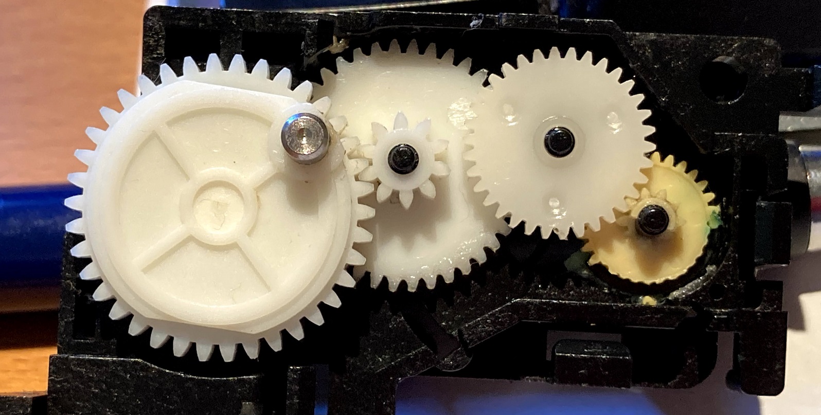
I disassembled the dead external floppy drive that I described in my previous post, and extracted the auto-inject SuperDrive mechanism that was inside. After carefully removing and opening the eject motor assembly, I discovered a gearbox with four plastic gears. And just as I’d suspected, one of the gears was completely trashed, with half the teeth missing. You can see the damage to the right-most gear in the photo. So now when the eject motor turns on, it can’t actually turn the gears to reach the desired position, and the motor spins forever. That’s the source of the continuous high-pitched whirring sound I noticed after the drive died.
I’m not sure why this happened. The miswiring problem that I described earlier would have made the eject motor run continuous eject and insert cycles, which isn’t good, but shouldn’t have destroyed the gearbox. Maybe these 30-year-old plastic gears were already brittle, and it’s just a coincidence that one broke when it did. Or maybe the continuous eject and insert cycles caused the gears to get hot, and the heat caused one to break.
With the eject motor assembly removed, inserting and ejecting disks manually, the drive can read disks OK. That’s a small consolation.
To continue testing, I’ll need to hunt down another auto-inject SuperDrive in working condition. I’ll also need some black- and red-label 800K drive mechanisms, since the red-label 800K that I found earlier also has a broken eject mechanism. Just my luck! For that drive, it looks like it’s a broken eject motor rather than a broken gearbox. It would be great if I could somehow make a working eject motor assembly out of the parts from two different broken assemblies, but unfortunately their gearboxes are different and not interchangeable.
Read 15 comments and join the conversationDeath of an M0131 Floppy Drive
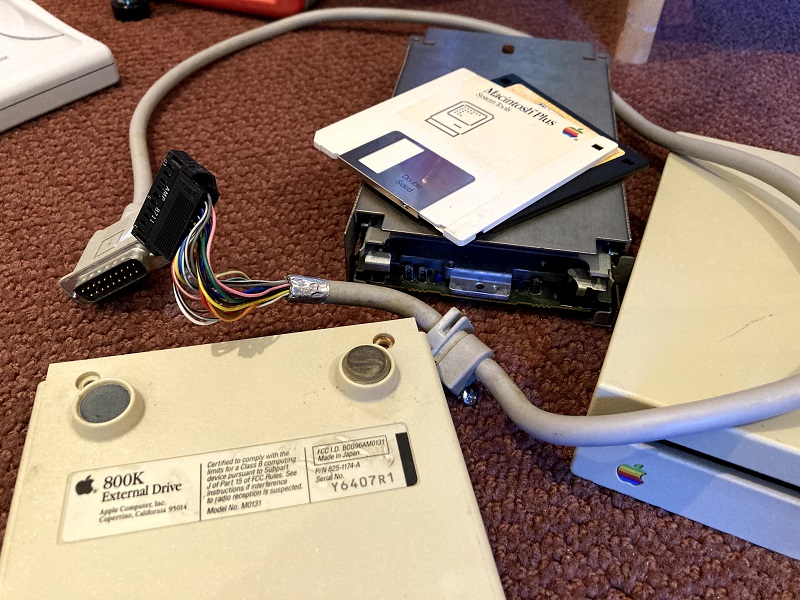
Recently I bought an external 800K Macintosh floppy drive, model M0131, so I could confirm its compatibility with my Yellowstone disk controller card for Apple II computers. The testing didn’t go as planned, and now the drive is dead, but it’s not Yellowstone’s fault. I’m still not clear exactly what happened. Here’s a rundown of my testing misadventures.
For the first test I connected the drive to a Macintosh SE, to confirm everything was OK before moving on to Yellowstone testing. This is the original SE model with an internal 800K floppy drive, not the later SE FDHD model that supports 1.44 MB floppy drives. Immediately after turning on the computer, the M0131 drive began continuously running its eject motor, trying again and again to eject a non-existent floppy disk. I quickly turned off the computer. Hmm, strange.
I connected the drive to a Macintosh SE/30. This time there was no strange eject behavior, but the drive made some ominous noises when I inserted a floppy disk. It was unable to read the floppy. That wasn’t good, but at least it seemed to be a small improvement over mystery ejections. So I returned to the Macintosh SE, naively hoping it would somehow behave differently this time. Nope. The drive still tried to eject-eject-eject for as long as the power remained on.
Back to the SE/30, I tried the drive once more and found success! I was able to read a couple of Mac floppies that I grabbed at random for testing. That was good news. Returning to the Mac SE for a third time, hoping that something would have magically changed there, the drive still tried to eject-eject-eject. This time I let it run for a while, under the theory that maybe it would stop ejecting after the System started to load from the internal hard disk. After 10-20 seconds, the eject-eject-eject cycles gave way to a continuous high-pitched whirring, and an unpleasant smell appeared. Uh oh… Moving back to the SE/30, now I could only get the same continuous high-pitched whirring, and no drive function. It seemed that the magic smoke was released. RIP, brave M0131.
Next I disassembled the drive enclosure. There was nothing of interest inside except for the drive mechanism and some brackets – there are no other electronics. So the M0131 external drive is essentially just an internal 800K floppy drive in a plastic box with a DB-19 to rectangular 20-pin cable. I tried to remove the drive mechanism to inspect it more closely, since it’s fully enclosed in a sheet metal tray. But one of the mounting screws was crusty with age, and I was unable to remove it, no matter what tools I used or how hard I tried. Unfortunately that means I now have a $100 doorstop.
-12V Strikes Again?
What happened here? I have a theory it’s somehow related to my old friend pin 9, which may be either -12V or +5V depending on the particular drive and the computer model, and which I’ve discussed here several times over the past weeks. I’m vaguely aware that continuous ejection is a somewhat common symptom of floppy drive cable problems in the earliest Macintosh models. If you mix and match floppy drives and drive cables between mid-1980s Macintosh models like the Plus, SE, 512K, and 128K, you will sometimes see this mystery ejection behavior. Internet wisdom says the solution is related to using yellow-striped disk cables instead of red-striped cables, but I’ve never bothered to understand the root cause or what the difference is between those cable types. You’ll find one discussion of this issue at VCFED, where one of the commenters also specifically mentions pin 9.
This is just a guess, but it wouldn’t surprise me if the original model Macintosh SE has a -12V supply connected to pin 9, but the newer Macintosh SE/30 has nothing on pin 9. If this M0131 drive has +5V on pin 9, and the short-circuited voltage supplies somehow caused the eject motor to unintentionally activate, that might partially explain why the drive worked on the SE/30 but not on the SE. But it still doesn’t entirely make sense, because the M0131 should definitely work on a Macintosh SE, and it was released a year before the SE. Maybe the drive mechanism in this particular M0131 was just bad, or the cable?
An 800K Impostor?
I have another crazy theory which is probably wrong. Maybe this was actually a 1.44 MB drive mechanism in a M0131 enclosure, the result of somebody’s past Frankenstein experiment or an “upgrade” when the original mechanism failed. From past testing, I know that pin 9 on the 1.44 MB drive mechanism is +5V. Maybe on the 800K mechanism, pin 9 is N.C., not connected? If that’s true, and my guess about pin 9 on the Mac SE and Mac SE/30 is also true, then it could explain everything that happened here. An M0131 enclosure with an 800K mechanism on a Mac SE would result in -12V connected to N.C., and would work OK. The same equipment on a Mac SE/30 would result in N.C. connected to N.C., and would also work OK. If a 1.44 MB drive mechanism were transplanted into the enclosure, with +5V on pin 9, it would result in N.C. connected to +5V, and would still work OK. Any computer newer than a Mac SE would likely also work. But on the SE, it would result in -12V connected to +5V, creating a short.
Two pieces of evidence may be helpful here – one that supports this crazy theory and one that refutes it. From what little I can see of the drive mechanism while it sits inside the sheet metal tray, it doesn’t look like a 1.44 MB mechanism. I say that based on its distinctly old-school look, with lots of large discrete components visible on its PCB. The crusty old screw that defeated my attempts to remove it also suggests that the drive mechanism hasn’t been removed any time recently. But that may not be a reliable indicator of anything.
On the other hand, I belatedly realized that one of the floppy disks that worked briefly on the SE/30 was a high-density 1.44 MB floppy disk. This shouldn’t have been readable in the 800K mechanism of the M0131! At least I don’t think so. It’s a question I’ve never really considered before. All of the extra smarts necessary for 1.44 MB floppy support are in the computer – in the SWIM chip and in the system ROM software, not in the drive. So what actually is the difference between an 800K drive mechanism and a 1.44 MB mechanism? The 800K mechanism spins at different speeds depending on which track is being accessed; the 1.44 MB mechanism can do this too, or it can spin at a fixed speed for all tracks. My guess is that the only really important difference is in the read/write heads. The 1.44 MB drive probably has smaller heads that can read and write weaker magnetic fields, to support the closer bit spacing on 1.44 MB disks. But it wouldn’t completely shock me to learn that an 800K drive could also read 1.44 MB disks, albeit with a lot of errors and poor performance, if it’s connected to a computer with a SWIM chip like the Mac SE/30. So I’m not sure whether reading that 1.44 MB disk really proved anything one way or another.
Unsolved Mysteries
Now that the drive is dead, the answer to this mystery will unfortunately remain unknown. I’m still 99 percent sure that the M0131 and other Macintosh floppy drives will work OK with Yellowstone version 2.1, but confirmation will have to come from a beta tester. Meanwhile I have a cool paperweight.
But Wait, There’s More
I finally managed to remove the crusty screw and extract the drive mechanism, revealing that my crazy theory was correct, and it’s actually a 1.44 MB drive in an 800K M0131 drive enclosure. The part number MP-F75W-12G matches a known part number for Apple 1.44 MB drives, and the “2MB” text (the raw capacity of a 1.44 MB drive) also confirms it.
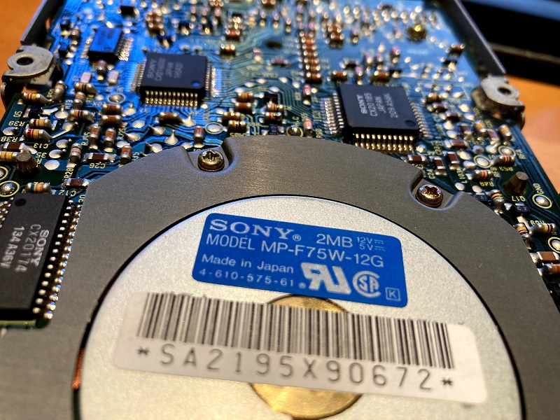
This seems to be an older example of a 1.44 MB drive than the one I’d previously been using for Yellowstone testing, and unlike that one, this drive’s pin 9 is not connected to +5V. It’s not connected to any other pin on the disk connector either. Unfortunately I can’t tell what pin 9 is connected to internally; I tried to follow the PCB trace but it disappeared into a confusing network of resistors and vias. Judging by the width of the trace, I’m guessing it’s a signal of some type rather than a voltage supply.
A few more pieces of data: The DB-19 to rectangular 20-pin cable on the M0131 enclosure connects DB-19 pin 5 to rectangular pin 9. That’s consistent with the expectation that this pin should be a -12V supply, and it’s where -12V is shown on the published pinouts of both types of connector. On the Mac SE, at the external DB-19 floppy port, I measured -11.7V on pin 5. But on the Mac SE/30, at the external DB-19 floppy port, I measured 0 volts on pin 5. I’m not certain if that reading on the SE/30 means the pin is grounded, or not connected, or something else. My prediction is that it’s not connected.
So now everything makes more sense, except for what the 1.44 MB drive was doing inside the M0131 enclosure. But I still don’t know what pin 9 on this 1.44 MB drive is intended to be used for, or why supplying -12V on the pin caused the drive to continuously eject.
There’s also a new concern for Yellowstone. Until now I had been building my plans for Yellowstone support of Macintosh drives from tests of one specific 1.44 MB drive, which I assumed would have the same pinout and behavior as any other Mac drive. It seems that I was wrong. On my original test Macintosh 1.44 MB drive, pin 9 is a +5V connection, and I designed the latest Yellowstone PCB version 2.1 around that fact. But on this Macintosh 1.44 MB drive, pin 9 is something unknown, maybe related to the eject motor. That means Yellowstone 2.1 may not work correctly with this type of Mac drive. It also raises the possibility that a true 800K Mac drive mechanism may be different than either of these 1.44 MB examples.
After almost ten years of making it my business to know everything possible about Apple floppy drives, I’m surprised to discover that something as fundamental as this drive pinout difference has escaped my attention. Live and learn.
Read 15 comments and join the conversation