

Wire-Wrap Photos
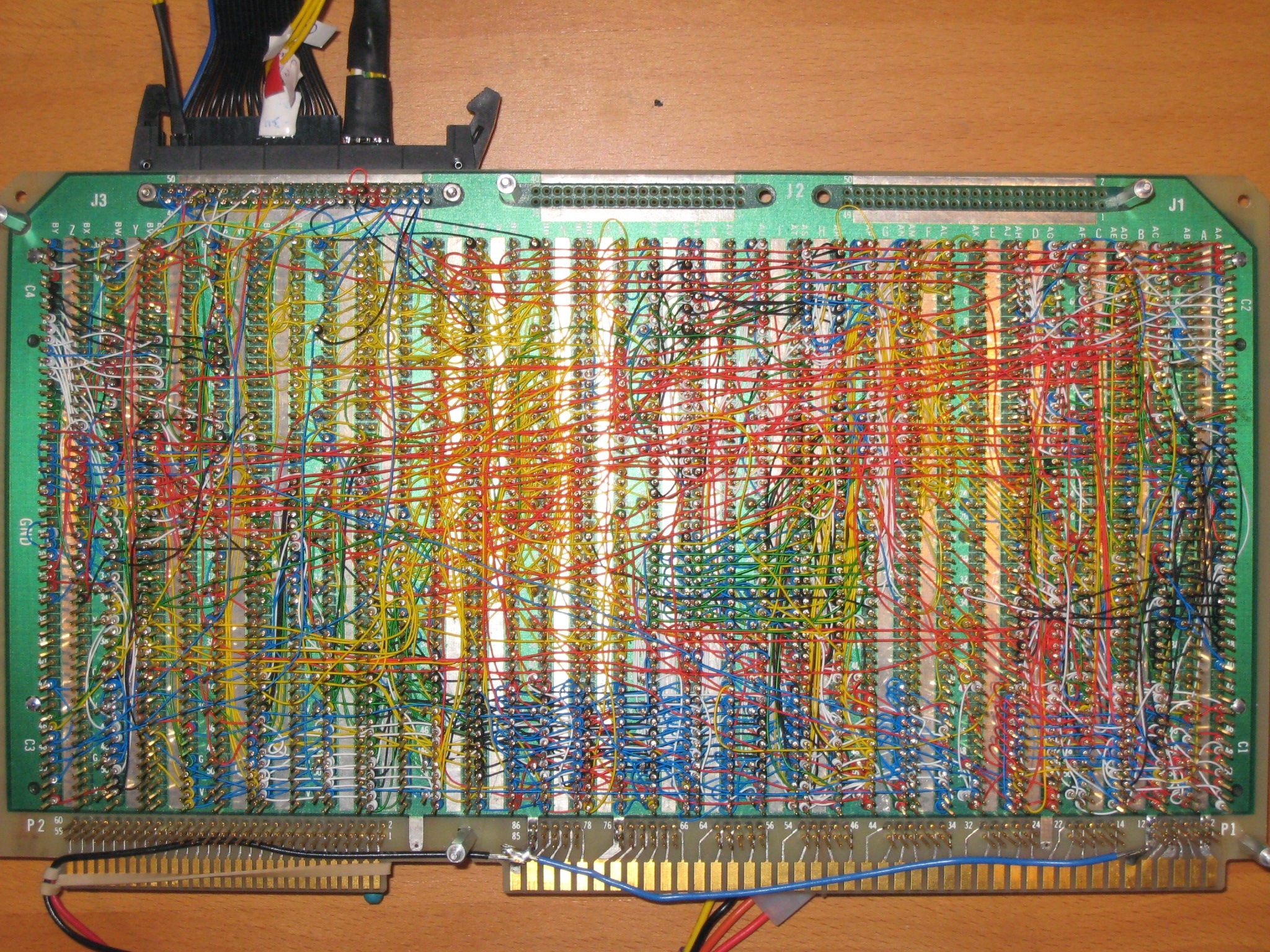
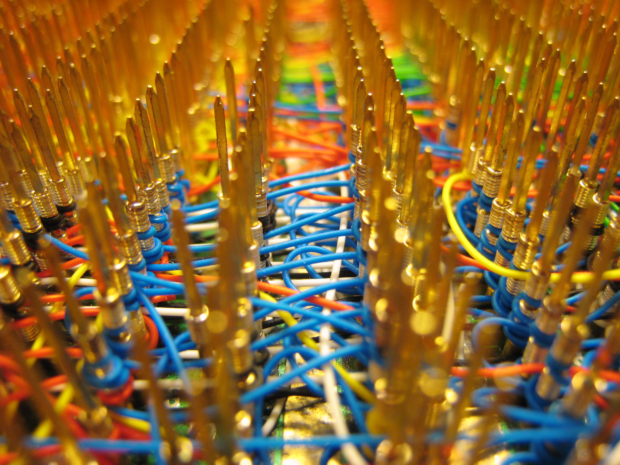
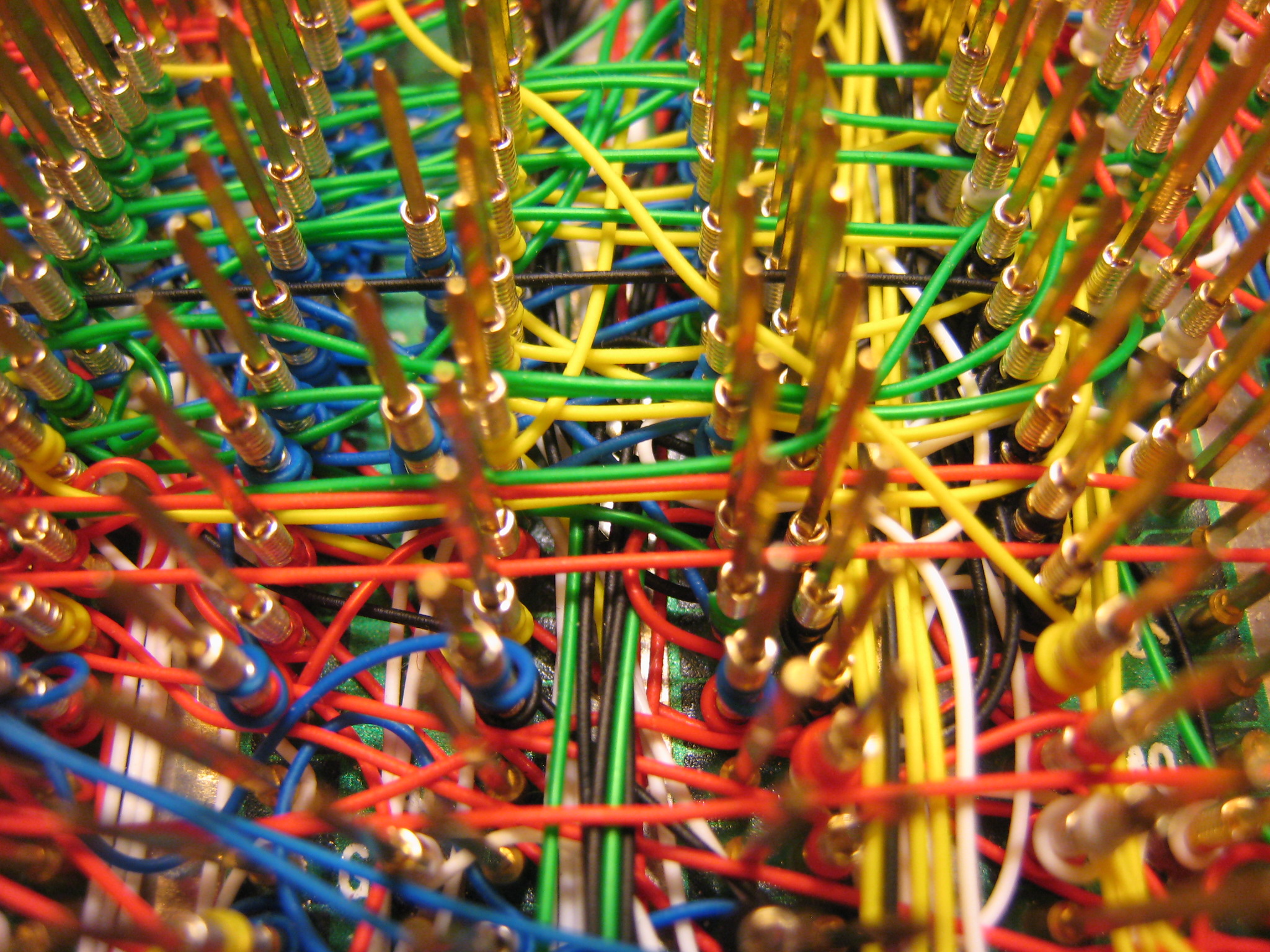
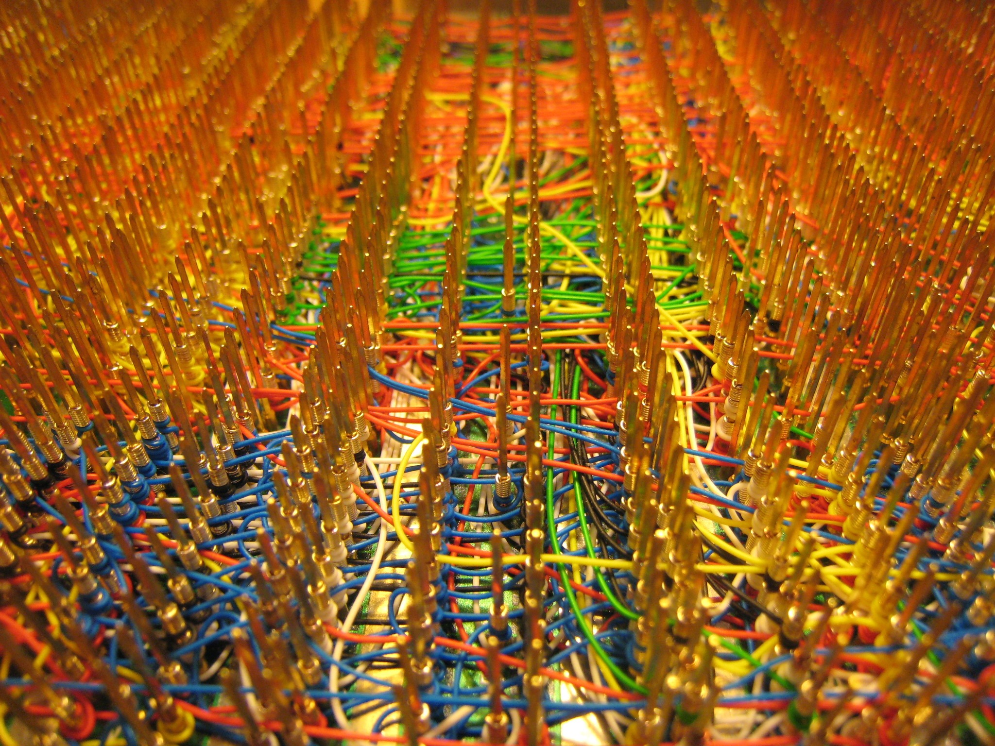
I finished wiring the audio circuitry for BMOW yesterday, which marks the end of wiring for BMOW… for version 1 at least! I took the opportunity to reflect on my wire-wrapping odyssey, and took a bazillion photos of the namesake Big Mess o’ Wires before it disappears forever into an opaque case. It’s really quite a sight. There are 1253 wires with 2506 individually-wrapped connections, and I’ve got every one logged in a spreadsheet.
At first I found the slow pace of wire-wrapping to be a chore, but eventually I came to enjoy it. Once I get going, I can wrap about 25 wires in an hour. It’s almost like a form of meditation. Despite how long it takes to wrap, the wire-wrapping hasn’t really impacted my overall rate of progress. Design, debugging, and general procrastination consume the most time, and wrapping is just a small part of the total.
All this craziness is built on a 12×7 inch Augat wire-wrap board with 2832 gold wire-wrap posts, which I purchased from eBay for $50. I started wondering about all that gold… are those posts solid gold, or gold-plated? I broke one once, and its cross-section appears to be solid gold. I know the boards sold for astronomical prices when new, and the name Augat suggests the atomic symbol for gold. The board was even listed in the precious metals section of eBay, rather than anywhere electronics-related. With a postage scale and a little figuring, I estimated the total weight of all the pins at about 10 ounces. Assuming it’s solid 10 karat gold, that’s 4.1 ounces of pure gold, with a value of about $3700 at today’s gold price. Too good to be true?
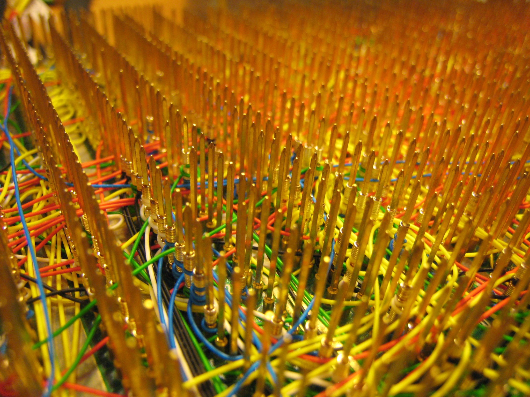
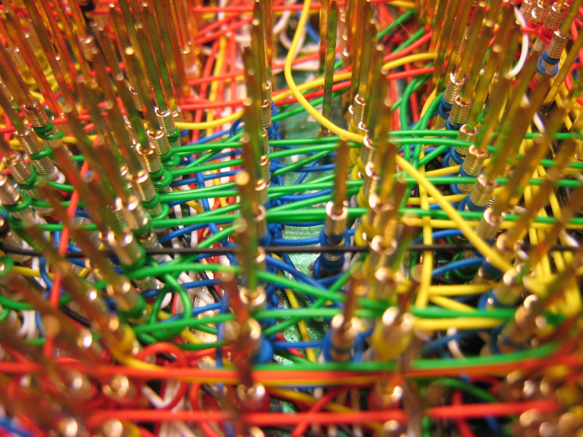
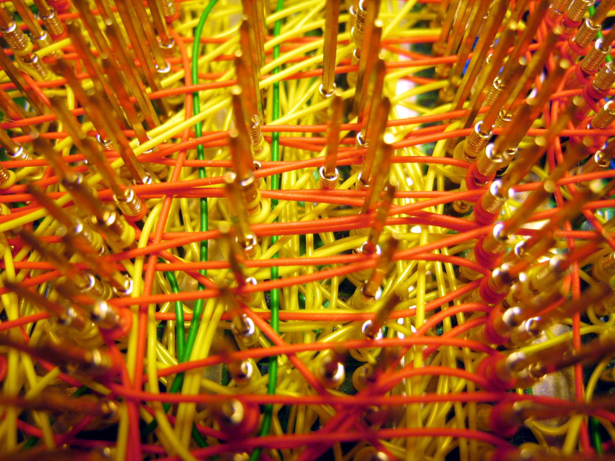
In the photos, I tried to capture the feeling of order amid chaos. Click any image to see the full-size version. What I found remarkable is just how dense the wiring is in many parts. The wide shots show off the surface wiring, but the close-ups really get into some interesting rats’ nests. In the densest channels, those wires are stacked at least 10 deep! It’s hard to believe it actually implements a computer.
Behold the insanity that is Big Mess o’ Wires!

Fun With Dremel
A while ago I purchased an old X-terminal and ripped out the guts, with the intention of using the case for BMOW. Upon opening it up, I discovered that the interior was partitioned into two parts by a steel divider welded to the base. The logic board was on one half and the power supply on another. Unfortunately BMOW needs the entire space in order to fit its oversized board.
Enter the Dremel tool. I got a Dremel and assortment of attachments for Christmas, but didn’t have a chance to try it until today. My plan was to simply cut the divider off, requiring about a 12 inch cut. The divider is made of 1/32 inch steel. Would the Dremel cut it? What kind of cutting attachment should I use? Would I slice off a thumb? I really had no idea how to use a Dremel, but a couple of the included attachments looked like cutting wheels, so I gave them a try. It took me about an hour and a half to make the 12 inch cut, and it looks pretty darn ragged, but the operation was a success. Sparks were flying everywhere… it was quite a sight! I ate up two entire cutting wheels, though, so I’m guessing a wheel made specifically for cutting steel would be better next time.
Here’s my handiwork. You can see the stump of the divider running from the case’s front to its back, about two-thirds of the way from left to right.
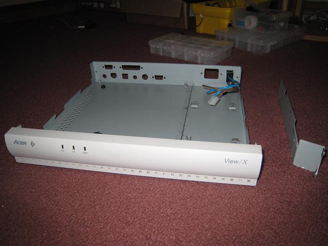
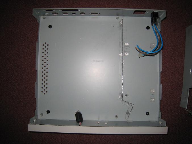
I had hoped to cut a large hole in the case lid, and cover it with a piece of plexiglass, to make a window where people could peer in and see BMOW’s guts. Given how this cut turned out, though, I think I’m going to abandon that idea. It would probably take me several hours to make a hole that large, and it would end up looked pretty ragged and ugly. Instead, I’ll just pop the lid when I do demos!
Read 7 comments and join the conversationArduino Repair
A brief note about the dead Arduino that I mentioned in the comments of my last post: I received a replacement Arduino, did some troubleshooting, and determined that there were multiple problems. I’d been using the original Arduino successfully to help test-drive my audio circuit before connecting it to BMOW, when in the span of five minutes it went from working to unresponsive. When the replacement Arduino arrived, initially it didn’t work either. I then tried both the old and new Arduinos on a Mac (primary machine is a PC), and also tried replacing the Atmega 168 chip in the original Arduino with a new preprogrammed chip.
What I found surprised me. First off, my PC seems to have lost the ability to download Arduino programs via auto-reset. It works fine on the Mac, but on the PC I have to manually hit the reset button with Ninja-like accuracy at precisely the right moment, about 1.5 seconds after pressing the download button in the software. I know that auto-reset is resetting the board, because I can see the Arduino program restart, but it never transitions to the download step successfully.
The second discovery was that the Atmega 168 in the original Arduino is dead. I don’t know how I killed it, but nothing I could do would revive it, on PC or Mac, auto-reset or manual reset. After replacing it with a new Atmega 168 that’s preprogrammed with the Arduino bootloader, it works with the same limitations as the new Arduino. I don’t know if the bootloader got overwritten somehow, or the chip itself is toast. I don’t have the hardware needed to restore the bootloader, so it will have to remain a mystery.
Read 7 comments and join the conversationAudio Amplifiers
I am well and truly stumped when it comes to amplifying BMOW’s audio. Any sane person would have given up long ago. Mix the three voices down to two stereo channels, and send them unamplified to headphones, and it sounds decent enough. But mix them down to a single mono channel, amplify it, and send it to a small speaker, and it sounds distorted and crunchy. The problem persists no matter how I tweak the amplifier circuit.
Last week I convinced myself that the LM386 wasn’t up to the amplification task, and ordered a bunch of other low-voltage power amplifiers. They arrived yesterday, I tried them all, and the result was pretty much the same as with the LM386. I tried an LM386 clone from another company, a TDA7052N, TDA2822M, and a NJM2073D. None of them made any noticeable difference.
I’m beginning to suspect that the problem lies not with the amplifier, but with the way I’m mixing the channels. The AY-3-8913 datasheet shows all three channels wired directly together to get a single mono channel. That’s what I did, but does that make sense? What happens when one voice is driving its output high, and the other is driving it low, and they’re wired directly together?
The TDA2822M is interesting in that it can be configured as two separate stereo amplifiers, or a single, higher-power mono amplifier. I tried the stereo setup, driving two separate speakers, each connected to a single voice of the AY-3-8913, with the third voice unconnected. It sounded good! Wiring the third voice to one of the others sounded noticeably worse, but still not as bad as when all three voices are wired together.
I see a few options on where to go from here:
- Experiment to see if there’s a better way to connect the three voices than short-circuiting them together. Maybe connect them with low-value resistors?
- Put two (or three) separate speakers in the BMOW case, each driven by a separate amplifier, so the voices don’t need to be mixed.
- Build the mono amplifier circuit and live with the distortion.
- Omit the amplifier and speaker entirely, and use headphones and/or an external sound system.
Custom PCBs
While I wait for my new audio power amp chips to arrive, I’ve started looking at making a custom PCB or two for BMOW’s various buttons, connectors, and jacks. I plan to use a pizza-box case from an old X-terminal that’s the perfect size, and already has case cut-outs for VGA and keyboard connectors, and other goodies. I could try to use all panel mount connectors with wires running back to the BMOW board, but some parts like the VGA and keyboard connectors typically only come in PCB-mount varieties.
I plan to design a simple PCB of about 1×5 inches, which will hold the various connectors, as well as the audio amplifier and related circuitry. It will be a long narrow board mounted in the back of the case, right next to the cut-outs, with headers for connecting cables internally back to the BMOW board. Of course I don’t really need to do this, but it’ll help make everything look neat and professional, and I’ve been looking for an excuse to design a PCB for a while. I know nothing at all about the design process, but I’m interested to learn. I will definitely keep this to a 2-layer or even 1-layer design, to keep it as simple as possible.
I wrote a little bit about some PCB manufacturing options in a comment to a posting last summer: /2008/08/17/wire-wrapping-pain . At this point I think I’ve narrowed the choices to ExpressPCB and their free, proprietary CAD tools, or the free version of Eagle PCB and Futurlec’s manufacturing service.
ExpressPCB looks very easy to use, and easy to submit designs, with very quick turn-around on manufacturing and shipping. That’s pretty important, because I’m notoriously impatient. Their “miniboard” package gives you three copies of a 3.8 x 2.5 inch board for $51 plus shipping. Unfortunately their software seems pretty basic, and its built-in library of components isn’t great. It also locks you in to their proprietary file format, with no easy way to export your design to other programs and manufacturers later.
Eagle PCB seems to be the standard tool for hobbyists making PCBs. It looks more full-featured, but with a steeper learning curve for newbies like me. The free version has a size limit of 8×10 cm (3.9 x 3.1 inches). Futurlec will accept Eagle files, and turns around orders in 7-10 business days. The cost for a single board comparable to ExpressPCB’s miniboard is $31, or $43 for three of them, plus shipping. They’re in Thailand, but were able to ship my last parts order to me in just two days, and it had some cool elephant stamps on the package to boot.
Given these size constraints compared to my desired 1×5 board size, I’ll probably try to design a board with half the connectors on one side and half on the other, and get two of them. Then I’ll put the two boards side-by-side with one rotated 180 degrees, and populate half of each board with the appropriate connectors. It’ll be two 3.8 x 1.25 logical boards sharing each 3.8 x 2.5 physical board.
I’m leaning towards Eagle PCB + Futurlec, but I plan to play around with them both for a while, and see what sticks. It should be fun!
Be the first to comment!Mixing and Volume
I’ve done some more breadboard experiments with the audio output circuit, but I’m having a lot of trouble getting it all to work as intended.
First the good news: I built the LM386 amplifier section, and it pretty much works. I purchased a five-conductor headphone jack, which passes the left and right channels through to the mono amplifier section when nothing is plugged in, but disconnects the amplifier section when a headphone plug is inserted. The only problem is that even when disconnected, the amplifier section still picks up a faint copy of the audio signal (from antenna effects or power supply noise?) and amplifies it. Ideally the amplifier section would be switched off entirely when a headphone plug is inserted, instead of merely disconnecting its input signal.
The bad news: The portion of the circuit before the headphone jack seems able to mix three channels into two, or to control the volume, but not both. The AY-3-8913 has three separate voices: A, B, and C. I want to mix them so that A is on the left stereo channel, C is on the right channel, and a half-volume copy of B is on both channels. This job is done with a resistor network. I also want to control the output volume with a potentiometer. Below are two similar circuits for performing these tasks. Although it’s not shown here, both circuits have their L and R outputs connected to the headphone jack, which in turn is connected to the speaker amplifier section as described above.
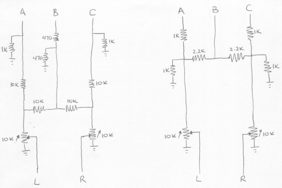
On the right is the “Polish circuit” I mentioned in my last post, with a 10K stereo audio potentiometer added at the output. On the left is a circuit I found on a ZX Spectrum hacking site, also with an output potentiometer. Neither circuit included a potentiometer originally.
You can probably see where this is going: the functions of mixing and attenuation conflict. Mixing works because the total resistance between A, B, or C and L or R is different for different paths. In the case of the Polish circuit (right side), if the potentiometer is turned all the way so there’s zero resistance between input and output, then the total resistance from A to L is 1K, from B to L is 2.2K, and from C to L is 5.4K. There more than 5x the resistance for C to L versus A to L, so A appears mostly on the left channel, and very little of C appears on the left channel.
If the potentiometer is now turned almost to the other extreme, so there’s 9K resistance between input and output, the situation changes. Now there the total resistance from A to L is 10K, from B to L is 11.2K, and from C to L is 14.4K. These are all similar enough that all voices go to both channels more-or-less equally, and the stereo effect is lost. This is where I’m stuck: I can get stereo mixing, or volume attenuation, but not both at the same time. The circuit on the left uses larger resistors, so the loss of stereo is less pronounced, but the maximum volume level is quieter.
Some ideas for addressing this problem:
- Move the potentiometer to after the headphone jack. This would allow for volume control of the amplified speaker, which is mono anyway, but the headphone jack would always be at maximum volume. In practice this would make the jack only useful as a line-out, and not for headphones.
- Change the stereo mix so that A and B go to the left channel, and C to the right, with no common path between them. This is simple but non-symmetrical, and the 100% stereo separation may not sound very pleasing.
- Use a transistor or op-amp as a voltage follower, inserted before the potentiometer, so that changes in the potentiometer resistance don’t affect the resistor network used for stereo mixing. This might be the best solution, but I’m uncertain how to build it, and don’t want to add still more elements to an already large circuit.
- Buy a second AY-3-8913, and create a six-channel audio system with three voices on each channel. Ha ha.