

Making a Difference
It’s time for a change. I’ve made a lot of interesting software in my life, and built some fun hardware projects, but none of it was especially useful in the big scheme of things. The past year has seen lots of flux in my personal and professional lives, sending my thoughts in new directions, and I’ve been wondering why smart tech-minded people focus so overwhelmingly on building random web sites and gizmos instead of something that might do real good in the world. Check out this list of AngelList startups: I could almost write those business summaries with a buzzword generator script.
I get it: saving the world doesn’t really pay the bills, and people need the lure of a big payout to justify all the time and hard work they put in. Business, communication, and entertainment are all vital and noble pursuits. Isn’t making a difference in someone’s life noble too? When such huge numbers of the world’s best and brightest devote their energies to projects like “a smarter restaurant menu for smartphones”, doesn’t that seem, well, wrong? Like if you were an alien newly arrived on Earth, and observed how humanity’s technology efforts were focused, you’d just scratch your head and say WTF?
So I’ve been thinking about ways I can make a difference, with my brain and my hands. I’m pretty comfortable with writing software, and not too bad at making hardware, so there’s got to be something I can do. I’m casting my net pretty wide, considering everything from the rural poor (as in the video above), to the elderly, the disabled, the sick, and anyone with needs more pressing than “my phone charger won’t reach my bed”. I’m just one guy without a lot of resources, but you’ve got to begin somewhere right?
My biggest challenge is knowing where to start, and what kinds of problems need solving. I have no first-hand experience with the day-to-day trials of people confined to a wheelchair, or people living beyond the reach of electricity and clean water, or any other groups outside my own circle of friends. So I’ve been searching around for ideas and inspiration to help get myself launched. Here are a few projects I found that resonated with me.
Sip and Puff Joystick – I first heard about this a year or two ago. It’s basically a one-man operation, building mechanical interfaces to enable quadriplegics to use game controllers for the Xbox and Playstation. Helping people to play video games may not seem like “making a difference”, but in this case I’ll argue that it is. If you’re a young person who’s left by accident or illness with no good way to interact with your friends, those friendships may wither and die. Being able to compete with others and keep a social life going is HUGE.
Gravity Light – The first time I saw this, I literally slapped my head. Why didn’t I think of this? It’s a super-bright LED light, powered by a falling weight. Hang it from the ceiling, fill the weight bag with a few pounds of dirt, lift the weight, and illuminate the room for 30 minutes. There’s no need for mains electricity, no battery system like you’d need for a solar kit, and no harmful indoor pollution from a kerosene lamp.
Contact Lenses for Diabetics – This was a Google project, not something from a solo inventor, but it hit the news recently and got me thinking. The promise of a “smart” contact lens to monitor blood sugar levels (instead of a finger prick to draw blood) sounds like a real step forward. Though one diabetic scolded Google for a well-intentioned but misplaced effort, since the majority of the world’s diabetics lack the money and access to medical care needed to benefit from this project.
Philips LightAide – My wife brought this home from work yesterday, and to be honest I’m not exactly clear what it does, but it’s an LED light board intended for kids with vision and cognitive difficulties. It’s certainly part of the “tech to make a difference” space, and I’ll try to learn more about it.
Smartphone Interface for the Blind – On several past occasions, I’ve wondered how blind people make use of iPhones and other smartphones. Is it even possible? Is voice recognition and text-to-speech enough? The smartphone has become a nearly indispensable tool for many, so it’s a cruel irony that its featureless glass screen is actually worse than an old phone’s from the blind’s standpoint. What if the screen had a dynamic tactile interface, maybe some kind of Braille peripheral that plugged into the phone?
What similar projects have made you think “aha!”? Got any great ideas of your own for something that would make a difference?
Read 4 comments and join the conversation
Building the Blinky POV

My oldest daughter Alice has an occasional interest in electronics, and as her dad I try to encourage her without becoming too annoying. We’ve done some past projects like Snap Circuits experiments, building a Drawdio pen, and constructing an animated Halloween LED display. Recently we had a chance to build a Blinky POV from Wayne and Lane. Or more accurately I should say she had a chance to build it, since my role was limited to talking her through the steps and taking photos. It’s impressive what an 11-year-old can do with a soldering iron!
You’ve probably seen these POV blinkers before. It’s like a scrolling message display, but with only a single column of pixels. The eye’s persistence of vision reveals the message when the display is waved back and forth across your field of view. There’s not much to the hardware: just a basic microcontroller, some LEDs, and a few passive components. Wayne and Lane’s instructions are detailed and well-illustrated, and even for this relative beginner it took less than an hour to build. The microcontroller (a PIC 16F1823) comes pre-programmed with some sample messages, so you can start using it as soon as the assembly is complete.

hard at work soldering

the nearly finished board
The main reason I selected Wayne and Lane’s Blinky POV instead of another similar one was the novel method used to program it. Instead of a PIC programmer, a serial connection, or some other conventional interface, it uses a pair of photo sensors to program new messages using flashes of light. Go to the Blinky Programmer web page, design some pixel or text-based messages, and click “go”. A clever bit of javascript flashes two squares on the screen, and when the Blinky POV is held near these flashing squares, it reprograms the stored messages in about 30-60 seconds. In our experience this method was very reliable, and much less hassle than dealing with virtual serial ports or other wired interfaces. And it actually made programming fun – like magic! The web page interface is surprisingly versatile, too. You can design pixel art or text messages, adjust the scrolling speed, switch between multiple stored messages, and define what should happen at the end of each message.
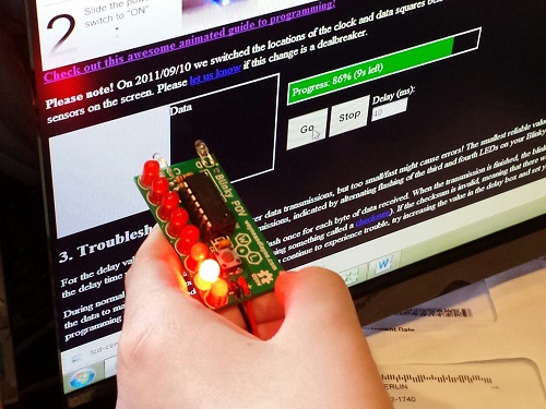
reprogramming using photo sensors
This is starting to sound like a Wayne and Lane commercial, so I should probably add that I have no affiliation with them other than being a satisfied customer. If there’s a young builder in your life who might enjoy a simple but fun-filled electronics project, give Blinky POV a try.
Be the first to comment!
LCD Contrast Adjustment in Firmware
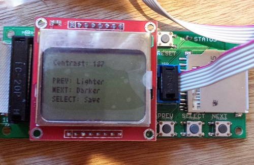
Floppy Emu uses a generic LCD that’s a clone of the display in the Nokia 5110 phone. It’s a nice little bitmapped display with a good range of configuration options, including the ability to set the display’s contrast level through software instead of with an external resistor. Unfortunately there’s a huge variability in contrast response from one LCD to the next, and even the same LCD can exhibit contrast changes from day to day. I’m not sure if it’s due to temperature, fluctuating voltages, bad solder joints, or something else, but it makes it virtually impossible to choose one contrast level in the Floppy Emu firmware that will work well for all LCDs. Until now, I’ve been making a custom firmware build for each Floppy Emu that I assemble, with a hand-tweaked contrast level, but that’s a huge pain in the butt. No more!
Firmware 1.0L F11 introduces the ability to adjust the contrast level and save it to EEPROM. Now you can tune the contrast exactly how you like it. To adjust the contrast, hold down the SELECT and NEXT buttons while Floppy Emu is initializing (after pressing the reset button, or when first powering it on). After a few seconds, the contrast adjustment screen will appear. Press PREV and NEXT to tune the contrast level, and SELECT to save the contrast setting to EEPROM. Easy peasy lemon squeezy.
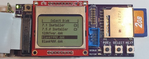
To apply this firmware update to your Floppy Emu hardware, download the firmware files, and copy the file femu.bin to your SD card. Then hold down PREV and SELECT while the Floppy Emu is initializing. This update only changes the AVR software (from 1.0K to 1.0L), the CPLD is unchanged (it’s still F11).
Happy contrasting!
Read 3 comments and join the conversationSelling the Floppy Emu
It’s been about a month since I began selling my Floppy Emu disk emulator for vintage Macs, and it’s time for a progress report. It’s been a real learning experience with the hardware, as well as on the “business” side of things. If you’ve ever considered turning a hobby project into a source of extra income, you may be especially interested in this side of the story.
The Biz
First, the business report: To date I’ve hand-built 44 of these little guys. 39 passed all my tests and received the seal of approval, for a yield of about 89%. Of the working boards, I sold 33, gave two as gifts, kept two for myself, and have two currently available for sale.
About half the Floppy Emus I’ve sold have gone to people outside the USA. Initially this surprised me – I’m in the USA, and I assumed most of the readers of my blog were too. Then there are large chunks of the world where the Mac was never popular, which are effectively ruled out as potential customers. And because the blog is in English, potential customers are further limited to those who are comfortable enough with the language to follow along. Yet despite all this, there are a surprising number of die-hards in Slovenia, Brazil, and other unexpected places who are buying Floppy Emus. Hello! So if you’re in the United States and considering selling some kind of DIY product, don’t make the mistake of ignoring the international market.
For a while I was operating a waiting list, but it was a bigger hassle than it was worth. Only about half the people on the waiting list actually followed through to make a purchase once I told them their board was ready. It was also awkward to reserve units for people on the waiting list, who may or may not eventually buy them, when it meant there weren’t enough units for the people who came later and were ready to buy.
Assembly and Test
All the Floppy Emus are built by hand, by me, with a regular soldering iron. It’s a fairly labor-intensive process, and with orders averaging about one per day, it’s monopolized most of my free time for the past month. I’ve been building boards in small batches of three to five at a time, updating the stock on the web page as new boards become available. This has created a pattern where Floppy Emu is constantly going in and out of stock, and I haven’t yet been able to get far enough ahead to keep a steady stock available. I guess that’s a good thing as it means there’s demand, but it would be nice if I weren’t always on the edge of running out.
The 89% success rate is pretty bad. Or maybe it’s reasonable for a hand-assembled electronics item, but throwing 11% of the hardware in the trash is a frustrating and expensive way to do manufacturing. Not only do I lose all the money that went into those failed boards, I also lose the hours it took to assemble and test them. This is an area where I really need to improve. The defective boards failed in various ways that I couldn’t diagnose or repair. Some of them almost work, but exhibit occasional failures when reading or writing. Others are nothing but scrap.
I’ve looked into having an assembly shop build a batch of Floppy Emus, but I probably need to purchase 50 or 100 units at a time for it to be cost-effective. With a new manufacturer, there’s also a risk of some misunderstanding or error that would lead to delivery of 100 non-functional Floppy Emus, and I can’t afford that risk. There are also some elements that an assembly shop likely couldn’t accommodate with their standard process, like the edge-mounted DB-19 connector, and the LCD mounted on a separate module. So for the time being, Floppy Emus will continue to be hand-assembled.
Assembly is slow, and it’s not just the time spent soldering. Setting the AVR fuses, programming the chip, and adjusting the LCD contrast for each board takes a surprising amount of time. Just digging the next part out of the box eats a substantial amount of time too. With a dedicated work area I could leave all the parts laid out for easy access, but I have to get by with a small desk that’s also used for other purposes.
Each Floppy Emu is tested three times on three different computers: a 400K disk test on a Mac 512K, an 800K test on a Mac Plus, and a 1.4MB test on a IIsi. These aren’t just quick boot-up tests either: they’re read and write tests that fill an entire disk image, multiple times, using each of the two floppy connectors on the board. Each Floppy Emu goes through about 20 minutes of testing, but when testing multiple boards at once I can do one every 10 minutes with pipelining. That’s a lot of manual testing work, and it bloats the time per board beyond the actual assembly time. And of course if there’s a problem found during testing, more time is needed to troubleshoot and fix it.

Shipping and Handling
I used to think “handling” was just a bogus term used to rip-off buyers, but now I understand why the cost to ship something is not necessarily the same as the cost of postage.
For USA shipments, it takes me about 10 minutes to prepare one Floppy Emu to be mailed. How can it take 10 minutes just to put something in a box? I didn’t believe it myself at first, but I’ve timed myself doing it often enough to accept it. The buyer’s contact info needs to saved, so I can contact him/her later if necessary. Then the Floppy Emu has to go in an anti-static bag, and the bag gets sealed. I have to assemble a box, fill it with foam peanuts, wrap the anti-static bag in bubble wrap, and cradle it in the peanuts. Then I need to print a packing slip and an instruction sheet, stuff those in the box, close it up, and seal it all with packing tape. Then I need to feed a sheet of label paper into the printer, log into the PayPal web site, purchase and print the postage, and stick it on the box. I have newfound sympathy for mail room employees.
For shipments going outside the USA, it takes about 15 minutes to prepare one Floppy Emu for mailing. For unknown reasons, PayPal will not sell postage for International First Class mail. I need to log into a separate account at the US Post Office Click-n-Ship site, and copy the pieces of the address one at a time from the PayPal data to the Click-n-Ship page. Instead of a single blank field for the address, Click-n-Ship forces me to break it up into separate form fields for first name, last name, street address, city, postal code, etc. Often these don’t match well with the way addresses in other countries are formatted.
If any letters have accents, the form validation fails, and I have to reformat it manually. Méndez Núñez must become Mendez Nunez. Sorry. This reminds me of some traffic signs in the area of California where I live. Many local place names are Spanish, and some signs for Cañada College have it as Canada College. When I first moved to the area, I couldn’t understand why the nation of Canada was sponsoring a local school.
I discovered that shipping materials cost real money! For USA shipments I can use the free Priority Mail boxes, but for international mailing I need to buy appropriate boxes, which must be purchased 50 or 100 at a time. Anti-static baggies, bubble wrap, packing tape, and shipping labels all cost money too. I hadn’t really considered this when I did my original cost estimates.
Once everything’s packed and ready to go, I have to bring it to the post office for mailing, which is about a 20 minute errand round-trip. Sometimes I can combine it with another errand, but I often find myself spending 20 minutes in the car just so I can mail a single Floppy Emu package. Post-9/11 paranoia means we’re no longer allowed to put packages in neighborhood mailboxes, but must take them to the post office and put them in the mail drop there. For international packages, you’re not even allowed to use the mail drop, but must wait in line to hand the package to a retail employee in person, even if the postage was already purchased online. Fortunately my local post office workers don’t insist on this rule, and told me that putting international packages in the mail drop is fine.
Between testing, packing, and visiting the post office, I’m averaging at least 30 minutes of labor per Floppy Emu above and beyond the time it takes to actually build it. Combined with the costs of shipping materials, that’s a significant amount of overhead I hadn’t planned for.
Parts Sourcing
Getting the parts needed to build each Floppy Emu has proven to be more challenging than I’d expected. I’m buying most of the parts from DigiKey, but the prices are constantly fluctuating, and sometimes it’s cheaper to buy certain parts from another vendor. It’s a bit of a puzzle, every time I refill my supplies. For most parts, the unit price is substantially cheaper when buying many of them vs buying a single one. I’ve been buying the majority of parts 10 at a time, but vendors other than DigiKey typically have higher minimum orders or steeper discount curves that force you into buying large quantities. I had to buy 73 of those DB-19 connectors!
Two other parts costs I neglected to account for are shipping and sales tax. These two combined add about 20% to my total cost of parts. In theory I could avoid paying sales tax by showing the suppliers a sales tax exemption certificate, but that would involve a layer of government red tape I haven’t wanted to mess with yet. It would also mean collecting sales tax when a California resident buys a Floppy Emu, which is something I really should be doing anyway, but would be a pain in the butt.
I discovered another hidden cost of parts sourcing too, and it’s one that wasn’t obvious at first. Say I’m building widgets, and each one needs a sprocket and a lever. If I buy 50 sprockets for $4 each and 50 levers for $3 each, then my total cost of parts is $7 per widget, right? Well, not exactly. It costs $350 to buy 50 sprockets and 50 levers, and I won’t recoup that cost until I’ve sold 50 widgets. If I do this repeatedly, on average at any given time I’ll have the parts for 25 unsold widgets sitting on my shelf. That’s a cost of $175 that I’ll never get back unless I quit the business after selling some exact multiple of 50 widgets. It’s like a security deposit, or worse.
The Sincerest Form of Flattery
The last of the business surprises was the theft of the Floppy Emu name. Another person (or company?) in Europe has started selling disk emulators using the Floppy Emu name for their product. I won’t link to it and lend it extra page rank points, but you can find it if you try. As far as I can tell, it’s a PC floppy emulator and not compatible with vintage Macintosh computers, so it’s not going to accomplish much except for confusing people.
Biz Summary
If you’re getting the picture that there are a lot of unforeseen costs and unexpected time sinks involved, you’re right. Don’t feel too sorry for me, though: even after all of this, I still make money from selling Floppy Emus. But with all the labor involved, it’s basically like I’ve invented a new part-time job for myself. It pays more than minimum wage, but not by much. 🙂
Hardware
Enough of all this business stuff – let’s talk about what’s happening with the hardware! The good news is that Floppy Emu is working well in the wild, and I haven’t had any reports of major problems or incompatibility. The worst problem seems to be one I encountered myself: on my Mac 512K, maybe one in ten times the computer will fail to boot, and will show a Sad Mac error. I suspect this is because the drive speed emulation for the Mac 512K (and Mac 128K) is imperfect, and so the Mac sometimes freaks out when it thinks the floppy drive is rotating at the wrong speed. Newer Macs don’t use the drive speed signal and so don’t run into this problem. On the other hand, maybe it’s just something flakey about my 512K.
LCD
The LCD has been a source of headaches. About 10% of the LCD modules I’ve purchased have been defective in some way: damaged screens or dead pixels. That’s annoying, but the bigger headache has been varying contrast between LCD modules. Using the same software contrast setting, some modules show nice crisp text, some are washed out, and some are nearly solid black. I think it has something to do with how the LCD glass is mounted on the module, as I can usually change the contrast by pushing on the glass with my finger.
For the LCDs that don’t look good with the default contrast setting, I’ve been making custom firmware versions with a different contrast value, so every Floppy Emu that ships should have a nice display image. This isn’t a good long-term solution, though. It’s time consuming, and the customized firmware will be lost if the user ever applies a firmware update. People can make their own custom firmware, but it’s a hassle. What I probably need to do is add a manual contrast adjustment feature to the firmware, with the selected contrast value stored in EEPROM. Then everybody can tune the contrast exactly how they want it.
The revision 1.1 board that’s shipping now was designed to backlight the LCD, and the LCD modules have backlight LEDs built-in. After doing a few samples, though, I decided it looked better without backlighting. The backlight highlighted imperfections in the display glass, and gave it a washed-out look. All the Floppy Emus that are now shipping have the backlight disabled, but for people who really really want backlighting, they can add a 220 Ohm resistor at location R5 to enable it. A future board revision will have a through-hole footprint for R5 instead of a surface-mount footprint, to make it a little easier for modders.
Future Development
Time permitting, I hope to continue development of the Floppy Emu firmware. Some early adopters discovered that Floppy Emu works with the Apple IIgs, but it’s not as simple of a setup as I’d like. It works when the Floppy Emu is connected to the pass-through board of a real 3.5 inch Apple external drive, but not when Floppy Emu is connected directly to the IIgs. I’m pretty clueless when it comes to all things IIgs-related, so I’m not sure what’s going on, but I hope to find out.
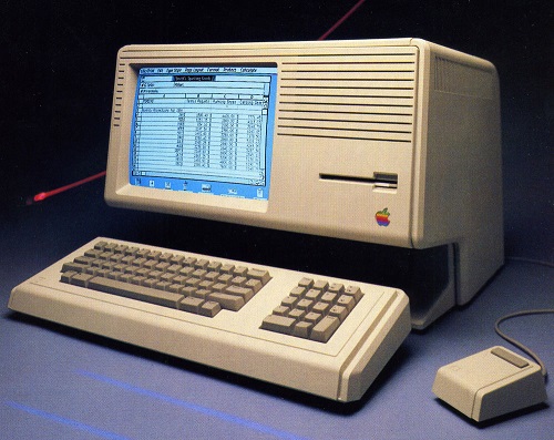
According to what I’ve read, it should also be possible to make Floppy Emu work on a Lisa – the precursor to the Macintosh. This would require a firmware change, since Lisa disks have essential data in the “tags” section of each sector, but the Macintosh doesn’t use tags and Floppy Emu ignores them. This may never happen, though, since the Lisa community is such a small audience of potentially interested people. I’m not ready to plunk down thousands of dollars for a Lisa just to test it out.
The most exciting thing on the horizon is HD20 support. The HD20 was a very early Apple hard drive from before the introduction of SCSI, and it connected to the external floppy port. In the past, several people have suggested HD20 emulation as a possible new feature, and I’ve always said it was impossible. But some new documentation that’s recently come to light suggests it may be possible after all – so Floppy Emu could emulate a 20 MB hard disk instead of an 800K floppy. In fact, it might even be possible to emulate hard disks larger than 20 MB. Unfortunately only a few early Macs have HD20 support in ROM, so it wouldn’t be a universal solution, but it would be great for those Macs that support it. It looks like HD20 emulation would involve a near total re-write of the Floppy Emu firmware, though, so don’t expect to see it next week!
Read 4 comments and join the conversation
Fixing Electronics with a Wooden Stick

I’m feeling pleased with myself today after fixing a dead hot air rework station. My technique? Whacking things with a wooden stick! I used the same method a few months ago to fix a dead Mac Plus, so it’s proven its worth yet again. What could possibly go wrong?
This technique is useful for electronics that were working fine, then became progressively more flaky, before finally dying completely. If you can coax a flash of life out of it by slapping the case with your palm, or rapping it with your knuckles, then you’re probably looking at a loose connection or a bad solder joint somewhere – but where? How do you find it?
In my case, I had a two year old Sparkfun Hot Air Rework Station that gave up the ghost. It started working intermittently, and would be fine one minute, but the next minute the temperature display would go dark and I’d get nothing but cold air blowing from the nozzle. For a couple of weeks I could usually “fix it” by tapping on the side of the case, but eventually it failed completely. I was prepared to throw it in the trash, but I decided to open it up first and see if I could diagnose the cause of the failure. Inside I found a lot of… parts. There was a PIC, and lots of discrete components, a transformer, and lots of cable harnesses. Nothing looked obviously damaged or burnt. Hmm.
Enter the hero of the story: a wooden stick. With the cover off, I turned on the power, and began gently tapping on all the different components. Do not use your finger or anything conductive to do this! You don’t want to short anything or electrocute yourself. When gentle tapping didn’t accomplish anything, I resorted to heavier force. Hey, it was already broken, so I couldn’t make it any worse! I finally discovered that if I gave U1 a hard shove (that’s the TO-220 just right of top-center in the photo), I could semi-reliably bring the hardware to life. The suspect was identified.
Fixing it proved to be another matter. After removing all the screws, that circuit board still wouldn’t budge. I needed access to the back side of the board to examine and troubleshoot the connections there. Again, I almost gave up and threw the thing into the trash, but persistence paid off. There are two large knobs on the front of the hot air station for controlling air flow and temperature, and it turned out that these knobs actually anchor the circuit board to the case. I had to unscrew the tiny set screw to remove each knob, then unscrew some nuts and other hardware, before I was able to get the board out. Sure enough, there was a cracked PCB trace right at U1. After a quick solder repair, the hot air station is now as good as new. Thank you, wooden stick!
Read 1 comment and join the conversationMastermind Game Rules, and Nibbler Near-Death Experience

And here’s why all your circuits should have some kind of reverse-polarity or over-voltage protection: I nearly killed Nibbler yesterday. I brought the hardware to a friend’s house for a nerdfest party, but when I demoed it, I accidentally plugged in the 9V AC power supply from Mozart’s Credit Card instead of the normal 5V DC supply. I’ve gotten lazy with my circuit designs, preferring to use an external regulated 5V supply instead of including power regulation on the board. Nibbler has no voltage regulator, rectifier, reverse-polarity protection, or fuse, so the 9V AC went straight to the power pins on all the chips. Baaaaaad!
Fortunately my mistake didn’t release the magic smoke from the chips. The speaker buzzed and the LCD showed some strange lines, and at first I thought a wire must have come loose during transport. It only took me about 10 seconds to recognize my error, and luckily Nibbler was fine after switching to the right power supply. If I’d left the 9V AC supply plugged in for longer, I think the board would have been toast.
Square Pegs in a Round Hole
Once Nibbler was up and running, we tried the Mastermind program that I wrote a few months back. It was a hilarious example of how six very smart guys can take fifteen minutes and a lot of arguing to solve a single Mastermind puzzle, but it also exposed some subtleties in the rules of Mastermind that I’d never considered before.
Most readers are probably familiar with the game: a codemaker chooses a four-element secret color code , and a codebreaker tries to guess it. After each guess, the codemaker gives feedback in the form of black or white pegs: a black peg means some element is the right color and in the right position, while a white peg means some element is the right color but in the wrong position. But what does that mean exactly, and what elements does it refer to?
Imagine you’re the codebreaker, and your guess is yellow-red-blue-green:

The codemaker comes back with three black pegs and one white peg:
![]()
Depending on your interpretation of the rules, you may think this is an invalid result, and the codemaker has made a mistake. After all, if three of the guesses are the right color in the right position, then there’s only one incorrect position remaining. The color guess at that position must either be correct (which would result in a black peg) or incorrect (which would result in no peg at all). Right? Wrong!
The critical question is whether the black and white pegs reflect the codebreaker’s guess with respect to the secret code, or the secret code with respect to the codebreaker’s guess. It might seem that it would be the same either way, but it’s not. Translated into pseudo-code, the two possible scoring algorithms are:
Secret-centric algorithm:
for (i in the range 1 to 4) {
    if (secretCode[i] == guess[i]) {
        emit black peg;
    }
    else (for j in the range 1 to 4) {
        if (secretCode[i] == guess[j]) {
            emit white peg;
            break;
        }
    }
}
Guess-centric algorithm:
for (i in the range 1 to 4) {
    if (guess[i] == secretCode[i]) {
        emit black peg;
    }
    else (for j in the range 1 to 4) {
        if (guess[i] == secretCode[j]) {
            emit white peg;
            break;
        }
    }
}
If we assume the secret code is yellow-green-blue-green:

and with the yellow-red-blue-green guess shown earlier, then the secret-centric scoring algorithm will result in black-black-black-white, but the guess-centric algorithm will result in black-black-black.
I think most people play the game using the guess-centric scoring algorithm, without realizing it. It seems more natural, as the score pegs are a reflection of how closely the guess matches the secret code, not how closely the secret code matches the guess. But surprisingly, I can’t find any definitive answer to which algorithm is correct. The online descriptions of Mastermind rules that I’ve found are vague on this point, or contradictory. The Wikipedia description of the rules implies both of these scoring algorithms are wrong, but isn’t specific enough to define an alternate algorithm. This page sounds like the guess-centric algorithm in its text, but the provided example uses the secret-centric algorithm. Unfortunately the official Hasbro game rules for Mastermind to Go only gives one example, which is ambiguous as to which algorithm should be used. The Parker Brother game rules are also ambiguous, and don’t give any examples. But the published rules for Pressman Ultimate Mastermind (which uses five colors instead of four) uses the secret-centric algorithm.
So how can we know which algorithm is the right one? I’m not sure we can. Mastermind is just a modern version of an old pencil-and-paper game called Bulls and Cows, which may date back more than a century. I couldn’t find anything definitive about the origins of that game or the correct rules. Ultimately it doesn’t really matter which scoring algorithm is used, as long as both players agree on it. For Nibbler I chose the secret-centric algorithm. Even though it’s less intuitive to me, it seems to be the most common choice among those people who pay attention to this quirk in the game rules. What do you think?
Read 2 comments and join the conversation