

Soldering Self-Confidence
I don’t like to solder. Nor am I very good at it, despite having soldered loads of boards. The temperamental solder never seems to flow where I want it. Surface-mount soldering in particular used to scare me enough that I didn’t even attempt it. A few years back, I gave Wired my opinion that surface mount chips are out of reach for non-professionals, or at least for anyone without advanced skills and special equipment.
Since then I’ve changed my outlook, and I now believe that successful soldering is primarily a matter of self-confidence. The only soldering project you’re 100% guaranteed not to complete is the one you don’t attempt. Sure, you might mess things up horribly, but you probably won’t. And even if you do make a mess so awful that it can’t be salvaged, what’s the worst that can happen? You’ll lose a few dollars worth of parts, but gain valuable practical experience. Consider it the cost of your soldering education.
I arrived at this conclusion after some reflection about my own soldering track record. I promise you, I am not a very skilled solder technician, and yet in all of the many boards I’ve assembled with countless hours of sweat, tears, and swearing:
- I have never destroyed a part
- I have never failed to get the board working
Some day I’ll screw up and ruin a part or a board, but the fact remains that the biggest thing holding me back from more complex soldering projects was not any particular skill or tool, but just the confidence to attempt the project in the first place.
BMOW Soldering Q&A
There are tons of great tutorials on the web about the mechanics of soldering, like how to bring the iron and the solder to the joint, and how to drag-solder SMD parts, so I won’t discuss that. Instead, I’d like to share some ideas about my overall approach to soldering, in the hopes that it may help others.
Soldering: Now With Undo!
Q: How can I prevent making mistakes when I’m soldering?
You can’t. I used to believe that soldering had to be done perfectly on the first attempt, and mistakes were fatal. Maybe I was vaguely aware of some techniques to fix mistakes, but assumed they were “advanced” techniques that didn’t apply to me. Nothing could be further from the truth! You wouldn’t expect to type a long document on a keyboard without a backspace key, and making and fixing dozens of typos is a normal part of the process. Soldering is just the same. Even on a small board, I normally make five or so soldering mistakes like bridges or misaligned parts, but I’m able to fix them quickly and move on.
Q: So how can I fix mistakes?
Solder wick (desoldering braid) is your friend. Got solder where it shouldn’t be, or too much solder on a joint? Lay the braid on top of the solder you want to remove, then press down on the braid with your iron. The excess solder will be sucked right into the braid. If you’re not soldering with solder wick, then your keyboard doesn’t have a backspace key. Get some.
Flux is even more useful than solder wick. Your solder may have some flux in the core already, but trust me, you need more. I use a flux pen that works just like a magic marker, enabling me to paint flux easily on to any joint or pad. Got a solder bridge between two chip pins? Apply some flux, then touch the pins briefly with the iron, and the bridge will often disappear. Got clumpy solder that doesn’t seem to want to flow where it should? Add more flux and reheat. Still not working? Add more flux. Then add still more. Flux fixes practically anything.
Q: I want a nice, professional-looking board. Won’t all that fixing look messy?
Yes, your board will probably look like crap, but it’s not a beauty contest. Let go of the idea that the board should look pretty. The only important question is whether it works.
Q: What if I make a mistake that I can’t fix?
Whenever I’m assembling a board, I always buy enough parts to build two of them. That way I’m less nervous about screwing up the board, because I can always trash it and try again with the second board if I make a huge mistake.
Before you trash a failed board, though, give it some extra effort in the attempt to fix it, and don’t be shy about it. Solder on some jumper wires. Burn things. Use a hammer. If you break it, you’re no worse off, but you’ll have gained more experience. Then try again with board number two.
Small Doesn’t Mean Difficult
Q: Some of those SMD parts are awfully small– those can’t really be hand-soldered with an iron, can they?
Yes, they can, easily. The surface tension of molten solder naturally makes it flow where it should, and soldermask deters it from flowing where it shouldn’t, even for very small parts. Mistakes are easy to fix with soldering wick or flux.
Q: OK, but what about those really tiny parts, with like 0.5 mm pin spacing?
Yes, those too. Easily.
Q: What about those plastic ribbon connectors on LCD screens, with the tiny metal contacts?
Those are even easier.
Q: But what about QFN parts that don’t even have exposed pins?
You can hand-solder those too, using an iron, by tinning all the pads on the board first. A hot-air tool makes it easier.
It’s Not About The Tools
Q: What do I need in order to do surface-mount soldering?
Not much beyond what you already have, probably. A regular iron with a regular tip is fine. I use the chisel tip that came with my iron, which is several times larger than the pins on the chips I’m soldering. It’s fine if the tip is larger than the pins, because you’re not going to do pin-by-pin soldering of SMD chips. In fact, for all but the largest SMD packages, the iron tip will always be larger than the pins.
Other essential ingredients:
- Flux. Use a flux pen, flux in a jar, or whatever other form works best for you. Flux everything liberally before soldering. Rule #1: If you’re having difficulty soldering a part, you need to add more flux. If that fails, refer to rule #1.
- Magnifier. Most SMD joints will be too small to see clearly with the naked eye. To inspect finished joints for tiny solder bridges or other defects, you’ll need something to magnify them at least 3x and preferably 10x. I use a cheap 10x loupe, which is like a monocle with a magnifying lens. USB microscopes also work well if you want something fancier.
- Tweezers. You need something to maneuver those little parts into place, and hold them there while you solder them. You’re hands aren’t going to cut it.
- Drug-Free Bloodstream. Your experience may be different, but I can’t do fine pitch SMD work within a few hours of drinking coffee. Even tiny amounts of hand twitching make it nearly impossible to align parts with sub-millimeter accuracy.
Circuit Debugging Is Fun
Q: How can I make troubleshooting easier when assembling a board?
Don’t assemble the entire board in one pass. I always assemble boards one functional section at a time, and test that section as much as possible before beginning the next one. This greatly reduces the number of possible causes that must be investigated if a problem is discovered.
The first section on nearly every board is the power section. Solder in the battery or power jack, voltage regulator, and other related parts. Next, measure the resistance between power and ground. Don’t just perform a continuity check, but actually measure the resistance. For most small electronics projects, it should be unmeasurable, or else in the megaohm range. If it’s below about 10K ohms, then you may have a very small solder bridge somewhere. If it’s zero ohms, then you have a dead short between power and ground, or a chip that’s soldered in backwards or something.
If the resistance checks OK, then turn on the power and measure the voltage on all the VCC pins. If it’s not what you expected then stop, and don’t proceed with further assembly until you’ve first fixed the power problem.
For microcontroller projects, I normally add the microcontroller next, as well as the programming header and any other components required to get the MCU running. Connecting with the external programmer and reading the device ID or fuses is a good way to verify that the MCU is working properly.
The remaining functional sections vary greatly depending on the project, but often there’s an LCD or other info display that can be tested first, and then buttons or other input hardware. After each section, recheck the resistance between power and ground before turning the device on, since each new part added brings a risk of an accidental short-circuit.
Q: I assembled the board, and the soldering all looks good, but it doesn’t work. What can I do?
In my experience, failures are almost always caused by short circuits (usually due to solder bridges) or open circuits (cold solder joints, or too little solder).
Short circuits are easier to diagnose, since they can usually be seen under magnification if you look in the right spot. Use your multimeter in continuity check mode, and test for continuity between every signal you suspect has a problem and its neighbors. If you’re fairly certain there’s a short, but can’t find it, then test again by measuring the actual signal-to-signal resistance instead of continuity check mode. For some types of signals, even a very small solder bridge with a resistance of 10K+ ohms can be enough to break the circuit, and those typically won’t produce a beep when in continuity check mode.
If that fails, visually reinspect every chip pin for possible hairline solder bridges to its neighbors, as well as bridges between pins and vias. If you see anything that looks like it could possibly be a short, then apply some flux and reheat the joint to clean it up.
Open circuits are a bit trickier, since they can’t be conclusively diagnosed just by looking at them. If the solder in a joint looks cloudy, or there’s very little solder, then check the continuity with your multimeter to make sure everything’s connected as it should be. When checking continuity to a chip pin, it’s important to touch the probe to the actual pin, and not to the pad underneath the pin, since the pin-to-pad joint itself is often a point of failure.
As with testing for shorts, it may be useful to test open circuits by measuring the actual resistance instead of merely performing a continuity check. If two points that should be connected measure 1K ohm of resistance between them, it may be enough to elicit a continuity check beep, but something is clearly wrong.
If all the continuity checking and resistance measuring fails to identify the problem, then you’ll need to perform live circuit debugging. Turn on the power, and start measuring voltages at various places in the circuit, verifying that the voltages are as expected. For DC voltages, this is easily done with a multimeter. For something like a clock signal with a 50% duty cycle, you can still use a multimeter, and expect the measured voltage to be 50% of the high-t0-low voltage swing of the clock.
For other time-varying signals and data signals, you will probably need to use an oscilloscope to observe what’s happening. A few common symptoms and their causes are:
- stuck at VCC or ground: short-circuit to power, ground, or another DC signal, or an unconnected signal.
- stuck at some middle voltage: contention (two different sources attempting to drive the signal), or an unconnected signal (open circuit).
- sort-of correct-looking signal, but reduced in amplitude and shifted far towards VCC or ground: hairline short-circuit to power, ground, or another DC signal.
- random wavy noise pattern: unconnected signal (open circuit).
If all else fails, then you may need to cut traces or remove parts from the board in order to isolate the problem. Remember, if it’s already broken then you’re unlikely to make matters worse, so don’t be shy about getting in there and banging away to debug the board.
Read 7 comments and join the conversation
FCC Testing For Open Hardware
What do small scale open hardware projects do about RF interference compliance testing? I’ve been looking into selling assembled versions of a few of my projects like the Backwoods Logger, to people without the time or skill to build their own. If I’m lucky, I might sell a few hundred such units, through a dedicated store web site, or just a page attached to the BMOW blog here. I would want to do this right, which means complying with any applicable certification requirements for consumer electronic devices. In the United Sates, that means FCC Part 15.
After searching for information about FCC requirements, it appears that anything operating at frequencies above 9 kHz requires FCC verification testing, which costs several thousand dollars. This is true for both intentional radiators (WiFi modules, Bluetooth, remote controls, etc) and unintentional radiators whose emissions are accidental. By that rule, everything from an Arduino clone to a data logger to a robot control board requires FCC testing. You don’t actually need an FCC ID, but you do need to perform the testing and keep your certificate of compliance on file, should the FCC ever ask for it. And your product must include a phrase like “This product complies with FCC requirements for a Class B device.”
I looked for information about how the “major” hobby electronics vendors handled FCC testing, and found that this is a topic no one wants to talk about. It’s like a dark family secret. Discussion threads get responses like “we can’t legally comment on this” and are then locked. Reading between the lines, it seems that while FCC testing is required for virtually every electronic board and module, almost no one actually does it. But because the penalties for non-compliance are worse if you knowingly sell an untested electronic product, nobody is willing to admit that they didn’t perform the tests, or even discuss the subject at all. I’m not going to name any specific vendors, but if you have any circuit boards on your desk that contain a microcontroller or USB chip or other interesting gizmos, check to see if it was FCC tested.
Have you ever sold an electronic product that you designed yourself? Have you ever taken a product through FCC compliance testing? What was your experience? Leave your feedback in the comments.
Read 13 comments and join the conversationClassic Mac Floppy Emulator Boot-Up
Exciting news on the Classic Macintosh Floppy Disk Emulator: I successfully transferred two sectors from a virtual 800K floppy disk, and used it to boot a Mac Plus to the “Happy Mac” screen. This proves that all the trickiest parts are working: the drive RPM speed feedback signal, emulation of drive registers, GCR data encoding, correct sector headers / footers / checksums, and modulation of the read sense line to mimic magnetic disk media. Woohoo!
There’s not enough memory to hold a full disk image, so the Mac won’t boot all the way to the Finder yet. More work is needed to load a track’s worth of data at a time and buffer it in RAM, using the Mac’s drive step command to trigger loading of a new track. And of course there’s still the whole question of floppy disk writes in addition to reads… but now that the initial hurdle of basic data transfer has been cleared, I feel much more optimistic about the remaining work.
As described in my previous post, a CPLD implements all the timing-sensitive functions, and generates the signals that are sent to the Mac. It creates an RPM feedback square wave whose frequency varies according to the current track of the emulated floppy drive, in order to mimic the variable-speed behavior of the Mac 800K drive mechanism. It also ensures bits are sent at exactly 2 microsecond intervals, using the transition encoding method of a real drive. This method indicates a logical 1 as a high-to-low transition during a 2 microsecond bit window, and a logical 0 as no high-to-low transition during the window.
To the CPLD setup, I added an ATmega168 AVR microcontroller with 16KB of program Flash memory and 1KB of RAM. The AVR stores two sectors worth of pre-encoded GCR data in Flash memory, and passes it to the CPLD one byte at a time, using ready/ack control signaling. If the AVR doesn’t signal its readiness when the CPLD needs a new byte, then the CPLD will automatically insert a sync byte. This makes it possible to emulate the empty space between sectors on a floppy disk without actually storing or transferring the sync bytes that appear in the inter-sector space. The eventual plan is for the AVR to also load disk image data on-the-fly from an SD card, or possibly over a USB link from a PC, perform GCR encoding on the fly, and also perform GCR decoding to support disk writes as well as reads.
Luckily my first attempt at transferring data wasn’t far off the mark, because the emulator’s Mac interface is nearly impossible to debug. Ideally I could step through the floppy driver routines in the Mac’s ROM while floppy data was being loaded, and see what’s happening at a low level and troubleshoot problems. This is sort of possible, by installing the MacsBug debugger on the Mac, and setting breakpoints inside the ROM driver routines. Unfortunately the Mac’s 68000 CPU lacks hardware breakpoints, so breakpoints in ROM code must be implemented by setting a processor flag to invoke an interrupt handler after every instruction. (RAM breakpoints are implemented by dynamically patching the code.) This makes the Mac run 100-1000 times slower than normal when a breakpoint is set in ROM, rendering it virtually unusable. But even if you have the patience to wait 10 minutes for a breakpoint, I found that my ROM breakpoints didn’t always get hit, though I couldn’t explain why.
After setting up the AVR data transfer and discovering that it didn’t work, I scratched my head for a while, trying to find tools to help determine what was wrong. The first problem I found was that the disk RPM speed feedback I thought was working correctly earlier actually wasn’t. I was able to use MacsBug to see that the floppy driver was returning error -79 “can’t correctly adjust disk speed”, but I had to blindly experiment with different speed values until I hit on one that worked. Then the floppy driver was returning error -67 “can’t find an address mark”, which basically means it can’t make any sense of the data to determine where a sector begins. With zero other info to help troubleshoot, I methodically went through all my design assumptions one-by-one again looking for mistakes, and found a place in the IWM specification where I misinterpreted what Woz meant by a “transition” on the read sense line. At fist I thought a “falling transition in a bit window” meant any transition that falls in the window, but it turns out it literally meant a falling high-to-low transition. After fixing that, holy cow, it worked! I had fully expected needing to dig through half a dozen more problems after that one, so I was literally jumping around and shouting in excitement.
Read 7 comments and join the conversationMacintosh Floppy Drive Emulator Update
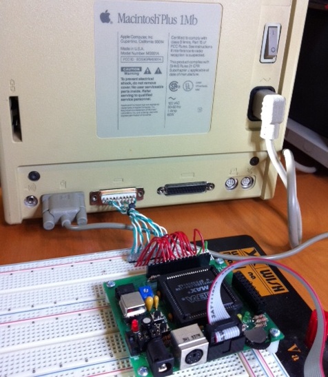
A couple of months ago, I posted a design sketch for an SD-card floppy disk drive emulator for classic Macintosh computers. Recently I finally got motivated enough to start building it. Using one of the oh-so-rare DB-19 connectors that I purchased a few weeks back, I rigged up a cable to connect the Mac’s external floppy port to a breadboard. Then I dug out an old CPLD board I built for an early Tiny CPU test, and wired all the floppy lines to the board’s I/O connector. The board is powered by the +5V from the floppy port.
This particular board has an Altera EPM7128S CPLD, which is so old that it actually runs at 5V (newer CPLDs run at 3.3V or below). That’s great for this purpose, because 5V is what the Mac provides and is also the voltage level on the Mac floppy data lines.
So far, I’ve built a successful blank disk emulator. It identifies itself as an 800K drive to the Mac, initially with no disk. Reading and writing of the interval drive registers works, as well as stepping the drive head. The PWM signal that tells the Mac the current drive motor RPM speed also works. By pushing a button on the board, you can “insert” a disk into the drive, but the disk is blank (it contains all 1’s).
If you push the button while the Mac is waiting for a boot disk, it thinks about it for a minute, then “ejects” the disk and shows the X-disk icon on the screen. If you boot from a regular floppy disk in the internal drive, then push the button to insert an external disk, the Mac asks “This disk is unreadable. Do you want to initialize it?” If you say yes, the Mac responds “Initialization failed! The disk is write-protected!”
It’s not very exciting yet, but it’s a good start. The next step will be to add a microcontroller and an SD card reader. With those pieces in place, I can start passing actual disk data to the CPLD, so it can pass the data on to the Mac.
Read 3 comments and join the conversationCortex M3 For Dummies – STM32 Discovery Board
The ARM Cortex M3 has generated lots of buzz lately. Maybe you’ve been working with Arduinos, AVRs, or PICs for a while, and heard about the Cortex M3, but weren’t sure what it was all about or whether it was even relevant to you. This review will try to shed some light on the Cortex M3’s capabilities and development tools, using the STM32VLDiscovery board from ST Microelectronics.
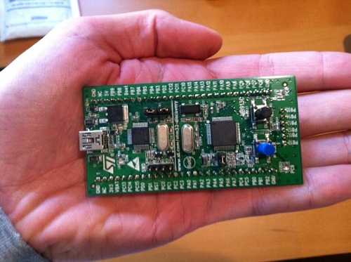
The nice folks at Newark sent me a STM32VLDiscovery Cortex M3 evaluation board for review. This little board packs a big bunch for a remarkably low price. It can be found for under $10 if you hunt around for a deal, which is an amazing value. ST is also currently running a promotion in which residents of the USA and Canada can get a free STM32F4Discovery board, which is similar to the board reviewed here.
Although the STM32 Discovery board isn’t marketed as an Arduino competitor, it could be one. Its size, layout, and functionality make it a reasonable replacement for many applications needing a small microcontroller board with lots of I/Os for experiments and mad scientist projects. To help put its specs into context, I’ve selected a few other boards that readers may be familiar with for comparison purposes. All the boards contain a microcontroller along with one or two buttons and LEDs, with I/Os connected to hobbyist-friendly 0.1 inch headers, and can be programmed with a plain USB cable. In addition to the STM32 Discovery, they are the Arduino Uno, Arduino Mega 2560, and Copper AVR32.
| STM32VL Discovery | Arduino Uno | Arduino Mega 2560 | Copper AVR32 | |
| Price | $10 | $25 | $50 | $38 |
| Processor | STM32F100 Cortex-M3 | ATmega328P AVR | ATmega2560 AVR | AT32UC3B1256 AVR |
| Type | 32 bit | 8 bit | 8 bit | 32 bit |
| Flash (KB) | 128 | 32 | 256 | 256 |
| EEPROM (KB) | 0 | 1 | 4 | 0 |
| RAM (KB) | 8 | 2 | 8 | 32 |
| Max Speed (MHz) | 24 | 20 | 16 | 60 |
| Voltage (V) | 2.0 – 3.6 | 1.8 – 5.5 | 1.8 – 5.5 | 3.0 – 3.6 |
| User I/O Pins | 51 | 20 | 70 | 28 |
| SPI channels | 2 | 2 | 5 | 3 |
| I2C channels | 2 | 1 | 1 | 1 |
| UART channels | 3 | 1 | 4 | 2 |
| ADC channels | 16 | 8 | 16 | 6 |
| DAC channels | 2 | 0 | 0 | 0 |
| USB | no | no | no | yes |
The table makes it clear that you’re getting a lot of microcontroller for your money. ST is very likely selling these boards at a loss, because their goals are different than the makers of the other boards. ST isn’t trying to sell you a prototyping product, but rather they’re trying to get you familiar with their line of STM32 microcontrollers so you’ll go on to incorporate them into a product of your own design. To appreciate this, it’s necessary to understand the ARM Model that gave rise to the Cortex M3.
The ARM Model
The Cortex M3 and other ARM processors were designed by ARM Holdings, a British semiconductor company. ARM doesn’t actually manufacture the processors they design, but instead they license the designs to other semiconductor companies, who then turn them into specific chips and sell them under their own brand names. Thus ST’s STM32 line of microcontrollers, Texas Instruments’ Stellaris line, NXP’s LPC1000 line, Atmel’s AT91SAMxx line, and many others are all Cortex M3 microcontrollers. All use the same instruction set, and have very similar features, so you could find a chip in any of those lines that’s a near functional equivalent of the STM32F100RB chip on the Discovery board. The chips aren’t exact clones, however. They differ in the amount of on-chip memory, clock speeds, pin configuration, peripheral units, and other features.
Unfortunately this is the Cortex M3’s biggest obstacle to gaining more traction in the electronics hobbyist community, because there isn’t really a “Cortex M3 community”. There’s a Stellaris community, and an LPCxxxx community, and an STM32 community, and so on. Each one is just different enough from the others to make manufacturer-independent tools and code sharing difficult. By fracturing the community into many different parts, it also makes it harder for it to reach a critical mass necessary to catch significant public interest in the way AVR and PIC have.
ARM Cortex M3
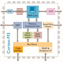
So what exactly is a Cortex M3? It’s a microcontroller, like an AVR or PIC. That means it has built-in Flash memory and RAM, lots of general-purpose I/O pins that can be controlled individually through software, and built-in peripherals for things like serial communication or analog-to-digital conversion. Where the Cortex M3 differs from 8-bit AVRs and PICs is that it’s a 32-bit processor, capable of running at speeds up to 100 MHz in some versions, and is a cousin of the higher-end ARM processors found in devices like Apple’s iPad and in some PCs. It also offers larger memories than typically found on AVR or PIC microcontrollers. In short, it’s like a beefed-up version of the micrcontroller you’re using now.
A few interesting features of the Cortex M3 aren’t found on typical 8-bit microcontrollers, like hardware divide support, an internal PLL for clock synthesis, and two digital to analog converters. The M3 also has a clever remappable pin feature, which lets you choose from among several options for which pins to use for I2C, SPI, USART, ADC, and other hardware units. This provides extra flexibility in board design and port usage.
The Cortex M3 has a newer sibling called the Cortex M0. The M0 is geared towards lower cost, lower power applications than the M3, but the two are very similar. Most of what you read about the M3 on the web also applies to the M0.
While it has arguably generated the most buzz lately, the Cortex M3 is by no means the only entry in the 32-bit high performance microcontroller market attempting to supplant 8-bit mcus like the AVR ATmega. Another example is the AVR32 chip, found on the Copper board. This 32-bit microcontroller is also made by Atmel, although it shares little with Atmel’s 8-bit microcontrollers beyond the AVR name.
The STM32VLDiscovery Board
ST’s name for their Cortex M3 product line is STM32, and the STMVL32Discovery board is the smallest and least expensive of their Cortex M3 evaluation boards. Now who is this woman that appears on all of ST’s marketing materials for the STM32 line? Her photoshopped eyes look a bit disturbing. Some of their STM32 materials also use a rainbow-colored butterfly logo, which I like much better.
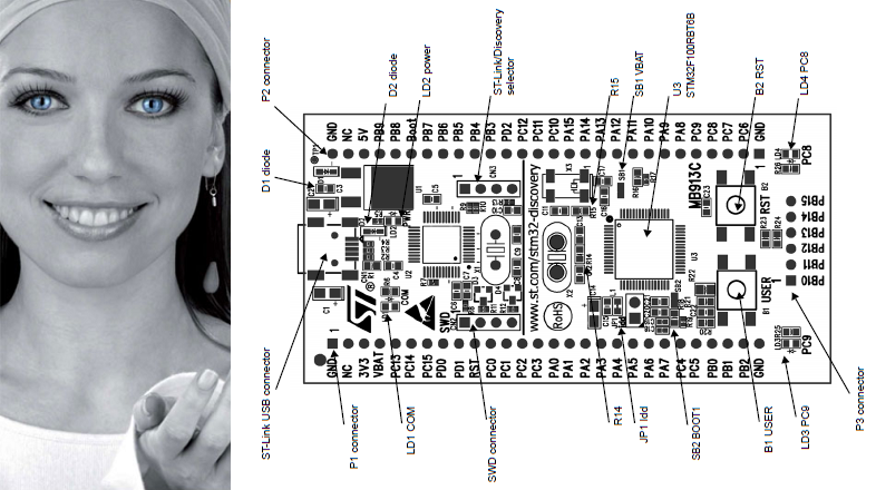
The STMVL32Discovery board is actually two boards in one: everything to the left of the vertical line in the above diagram is an ST-Link programming/debug module. It can be used with the Cortex M3 module on the right side of the board, or to program and debug a STM32 mcu on another board in a stand-alone application that lacks a programmer. I believe an earlier version of the ST Discovery board actually had perforations in the PCB so you could break-off the ST-Link module and use the two halves separately, but with the STMVL32Discovery there’s only a line in the silkscreen to remind you there are two functionally separate modules on a single board.
At roughly 3.3 x 1.7 inches, the board is smaller than a standard-size Arduino. Two rows of 0.1 inch header down the sides of the board make it easy to connect other components. The headers are on both the top and the bottom of the board, so you can make connections from either side, which is a nice touch. You could almost drop the ST Discovery right into a breadboard, except for the 6-pin header along its right edge. I’m not sure what ST was thinking here, because when inserted into a breadboard, these six pins will all be tied together in a single row. Depending on the layout of your breadboard, you may be able to insert the ST Discovery such that those six pins hang off the edge, unconnected.
Besides the Cortex M3 itself, the board also contains two user-controllable LEDs, a user push button, and a reset button. That’s similar to what you’ll find on an Arduino board, and is just enough to test things out and make sure it’s all working before connecting more components.
The board is powered over USB, or optionally from an external supply. When first connected to your PC, it immediately runs a demo program that flashes the LEDs in different patterns when you press the user push button. Under Windows it also automatically mounts itself as a read-only USB storage drive, which contains a few files with links to the online documentation. That’s pretty slick.
There’s no printed documentation included with the ST Discovery board, but the online user manual is quite well done. It includes a quick-start guide, block diagram, layout diagram, mechanical drawing, full schematics, explanation of all the jumpers and solder bridges, and a pin description table. The companion software package includes the libraries and header files for ST’s version of the Cortex M3 and for the ST Discovery board peripherals, as well as several example projects. On ST’s web site you’ll also find detailed tutorials for building and running the example projects using the three officially supported development toolchains.
ARM Development Tools

There are a bewildering number of development toolchain choices for ARM Cortex M3 development. It’s hard to overstate just how painful this makes the getting started process for a beginner. Worse still, the only officially-supported toolchains (IAR, Keil, and Atollic) are professional tools which are very expensive, and certainly won’t be of interest to any hobby developers. When their web page has a “get a quote” link instead of listing an actual price, that’s the clue to look elsewhere. For reference, the Keil tools cost $4895 for a single license, and the others are similar. Ouch!
The professional tools do all offer a time-limited trial version or a code size-limited version, but few hobbyists will be happy with those as a permanent solution.
If you’re willing to cough up a little money (but not $4895) for a well-made development tool with good support, Rowley Associates Crossworks is well-regarded and is just $150 for a personal license.
After looking at more than a dozen different development tools, I decided to put together my own toolchain based on the CodeSourcery CodeBench g++ Lite GNU command line tools and Eclipse C/C++ IDE. This excellent setup guide for Eclipse and CodeSourcery with STM32 describes the process in detail, so I won’t list all the setup steps here. Depending on your familiarity with other development environments and your tolerance for this sort of job, you may find the process anywhere from slightly tedious to completely impossible. It involves installing Eclipse, the Java runtime, CodeSourcery, GDB server, the STM32 SDK, and the ST-Link programming utility from six different sources, and then configuring them all to work together properly. It really makes you appreciate the convenience of a tool like Atmel’s AVR Studio, which performs all of the same functions in a single tool with a single download and install process. All together, it took me about 90 minutes to get the STM32 Cortex M3 development tools configured and program one of the example projects onto the ST Discovery board.
Cortex M3 Software Development
OK, let’s blink some LEDs. Here’s the simplest of the examples provided by ST:
#include "stm32f10x.h"
#include "STM32vldiscovery.h"
GPIO_InitTypeDef GPIO_InitStructure;void Delay(__IO uint32_t nCount);int main(void) { /* Configure all unused GPIO port pins in Analog Input mode (floating input trigger OFF), this will reduce the power consumption and increase the device immunity against EMI/EMC *************************************************/ RCC_APB2PeriphClockCmd(RCC_APB2Periph_GPIOA | RCC_APB2Periph_GPIOB | RCC_APB2Periph_GPIOC | RCC_APB2Periph_GPIOD | RCC_APB2Periph_GPIOE, ENABLE);GPIO_InitStructure.GPIO_Pin = GPIO_Pin_All; GPIO_InitStructure.GPIO_Mode = GPIO_Mode_AIN; GPIO_Init(GPIOA, &GPIO_InitStructure); GPIO_Init(GPIOB, &GPIO_InitStructure); GPIO_Init(GPIOC, &GPIO_InitStructure); GPIO_Init(GPIOD, &GPIO_InitStructure); GPIO_Init(GPIOE, &GPIO_InitStructure);RCC_APB2PeriphClockCmd(RCC_APB2Periph_GPIOA | RCC_APB2Periph_GPIOB | RCC_APB2Periph_GPIOC | RCC_APB2Periph_GPIOD | RCC_APB2Periph_GPIOE, DISABLE);/* Initialize Leds LD3 and LD4 mounted on STM32VLDISCOVERY board */ STM32vldiscovery_LEDInit(LED3); STM32vldiscovery_LEDInit(LED4);while (1) { /* Turn on LD2 and LD3 */ STM32vldiscovery_LEDOn(LED3); STM32vldiscovery_LEDOff(LED4); /* Insert delay */ Delay(0xAFFFFF);/* Turn off LD3 and LD4 */ STM32vldiscovery_LEDOff(LED3); STM32vldiscovery_LEDOn(LED4); /* Insert delay */ Delay(0xAFFFFF);} }void Delay(__IO uint32_t nCount) { for(; nCount != 0; nCount--); }
If you’ve previously developed software for other microcontrollers, then this probably looks fairly understandable. The first step is to configure all of the I/O pins as inputs, akin to setting the DDR (data direction) register on an AVR or calling pinMode() with the Arduino environment. In this case, the I/Os are configured by passing a struct to a function instead of directly twiddling some bits in a register, although it’s likely that the implementation of GPIO_Init() does something like that under the hood. That RCCABP2PeriphClockCmd() function looks a little strange, though– it appears the port’s clocks need to be explicitly enabled before configuration, then disabled afterwards.
The rest is just manipulation of the LEDs, but it’s a bit more abstract than most people are probably accustomed to seeing. You don’t normally need to initialize an LED or call a function to turn it on. These functions are provided by the ST Discovery board library to simplify development, but curious minds will want to know what they actually do. Here’s the implementation of STM32vldiscovery_LEDInit() and definitions of LED3 and LED4:
typedef enum
{
 LED3 = 0,
 LED4 = 1
} Led_TypeDef;
const uint32_t GPIO_CLK[LEDn] = {LED3_GPIO_CLK, LED4_GPIO_CLK};#define LED3_GPIO_CLK RCC_APB2Periph_GPIOC #define LED4_GPIO_CLK RCC_APB2Periph_GPIOCvoid STM32vldiscovery_LEDInit(Led_TypeDef Led) { GPIO_InitTypeDef GPIO_InitStructure; /* Enable the GPIO_LED Clock */ RCC_APB2PeriphClockCmd(GPIO_CLK[Led], ENABLE);/* Configure the GPIO_LED pin */ GPIO_InitStructure.GPIO_Pin = GPIO_PIN[Led]; GPIO_InitStructure.GPIO_Mode = GPIO_Mode_Out_PP; GPIO_InitStructure.GPIO_Speed = GPIO_Speed_50MHz; GPIO_Init(GPIO_PORT[Led], &GPIO_InitStructure); }
So STM32vldiscovery_LEDInit() enables the clock for port C, where the LEDs are connected, and then configures the correct pin in port C as an output. GPIO_Mode_Out_PP specifies a push-pull output, in other words a normal output that’s actively driven high and low. GPIO_Speed_50MHz controls the rise and fall times of the output signal. Selecting a faster speed will produce shorter rise and fall times, but will consume more current and generate more supply voltage swings and electrical noise.
Lastly, let’s take a look at STM32vldiscovery_LEDOn() and STM32vldiscovery_LEDOff():
void STM32vldiscovery_LEDOn(Led_TypeDef Led)
{
    GPIO_PORT[Led]->BSRR = GPIO_PIN[Led];
}
void STM32vldiscovery_LEDOff(Led_TypeDef Led) { GPIO_PORT[Led]->BRR = GPIO_PIN[Led]; }
Each port has a separate bit set (BSRR) and reset (BRR) register. Writing a 1 to the corresponding bit position for a pin sets the pin’s value to 1 or 0, depending on which register is written. Alternatively, all 16 pins of a port can be set at once by writing a 16-bit value to the port’s ODR register.
Note that all these GPIO_ APIs are specific to ST’s Cortex M3 library. If you’re using some other flavor of Cortex M3, then your method of controlling I/Os will be different.
Building the code and programming it to the ST Discovery board’s Cortex M3 is straightforward. Within Eclipse, select Project -> Build Project from the menu, and if all goes well you’ll end up with a .bin file. The LED blink example generates a 7K .bin file for the Debug configuration, and 5K in release. That’s a pretty big binary for just the few lines of code in main.c, but all those GPIO_ functions and other support libraries bloat the code further. Due to the larger size of Cortex M3 binaries, the larger Flash memory of the M3 as compared to an Arduino isn’t as significant an advantage as it first appears.
To program the board, launch the ST-Link utility program, and open the .bin file. Programming doesn’t automatically reset the board or launch the new program, though. After programming is complete, you can open the MCU Core dialog and press the System Reset button. From here you can also do other neat stuff like view all the mcu register contents, or single-step the clock.
Debugging
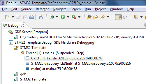
The built-in ST-Link on the ST Discovery board also supports live debugging of the program running on the Cortex M3. If you’re coming from the Arduino, or vanilla AVR development with an AVRISP mkII programmer that lacks debugging capability, this is a quantum leap forward. The people who wrote the Eclipse + Code Sourcery + STM32 setup guide also wrote an excellent hardware debugging setup guide, so I won’t repeat the steps here. Unfortunately, it involves downloading the entire Atollic Lite toolchain (250MB) just to get the ST-Link compatible gdbserver it contains. This also requires registering with Atollic, and getting a (free) activation key. It’s a hassle, but you only need to do it once.
Debugging works just how you’d expect. You can step through running code, set breakpoints, examine variable values, and view the call stack. Stepping through code seems unexpectedly slow, taking 1-2 seconds to step over a single line. The gdbserver also crashed a few times while I was debugging, and the only clue was that attempts to start a new debugging session failed with a generic error. I also found that stepping over a line that branches to itself, like
for(; nCount != 0; nCount--);
put the debugger into a state where the program was suspended, but the debugger thought it was running, forcing me to press the “pause” button to regain control. The overall debugging experience was a bit rough around the edges, but was much better than nothing. A different toolchain might have provided a smoother debugging experience, and I don’t fault the Cortex M3 or the ST Discovery board hardware for the debugging problems I encountered.
Beyond the Examples
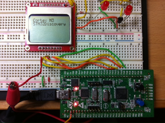
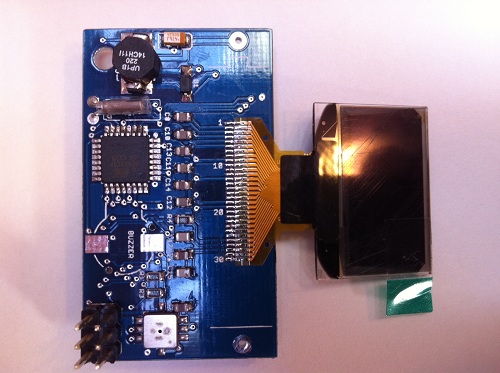
Running through the examples is a good way to get familiar with the Cortex M3, but to really learn what it’s like to develop for, there’s nothing better than creating your own custom project. Using the LED blink program as a template, I was able to port some code for controlling a Nokia 5110 LCD display, and print the message shown in the photo. The LEDs, transistor, and resistor in the upper right are from an unrelated circuit on my breadboard, and the only connections between the Discovery board and the LCD are the seven wires at the bottom.
My example program shows the code used to print the message on the LCD. There were no real surprises during development, and it only took me about 30 minutes to get the LCD working with the ST Discovery board. The only oddity I encountered was that there doesn’t appear to be a calibrated wait/delay function anywhere in the STM32 libraries. I wrote my own delay_ms() function that’s roughly accurate, assuming a 24 MHz clock and code compiled in the Debug configuration. It’s an imperfect solution, so if there’s not already a suitable delay function somewhere in another ARM library, it will probably be necessary to use a timer to get delays independent of clock speed and compiler options.
The GPIO_ library is great for getting projects up and running quickly. For high-speed performance-sensitive designs, however, there may be an unacceptable amount of overhead involved in calling a library function every time an I/O pin needs to be manipulated. In practice, the compiler may inline these functions when building Release configuration code, but I didn’t investigate to confirm it.
When powered by USB, the voltage at the ST Discovery board’s 3V3 pin is only about 2.97V, with no load. That might cause problems for some devices, but the Nokia 5110 LCD worked fine at that voltage.
Conclusions

Are the Cortex M3 and STM32 Discovery board what you’ve been looking for? In what kinds of projects do they fit best?
As an alternative to an Arduino or vanilla AVR board, the STM32 Discovery board looks like a clear winner in terms of price and hardware. It has more I/Os, more peripherals, larger memories, faster core clock MHz speed, and more performance per MHz due to its 32-bit internal design. All that, and it’s priced at less than half the cost of an Arduino.
What the STM32 Discovery lacks is easy-to-use development tools, and a large community of other users to collaborate with. The method I used to create a toolchain is probably too complex for many beginners, and they won’t be able to afford the commercial alternatives, so they’ll likely be shut out of Cortex M3 development entirely. Even if they do get the toolchain installed successfully, they won’t find the wealth of examples, 3rd-party libraries, or other support materials that exist in the AVR world. The value of that support shouldn’t be underestimated. Performance and memory aren’t everything.
The STM32 Discovery board is better matched for experienced microcontroller developers who’ve already done some work outside the Arduino environment, and are ready to accept additional complexity in exchange for major hardware improvements. The 24 MHz 32-bit Cortex M3 on the STM32 Discovery board is already a nice step up from 8-bit AVRs, but it’s just the beginning of the Cortex M3 line. Higher-end members of the Cortex M3 family can perform complex real-time tasks not possible on an AVR, drive high resolution color displays, run a real-time micro-OS capable of scheduling many programs at once, or even run Linux. For those who need this kind of power, the Cortex M3 is a great choice.
Read 10 comments and join the conversationBLsync
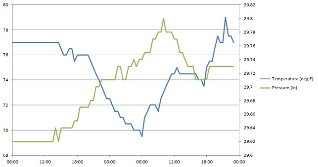
My newest design is a PC downloader utility called blsync, created as part of the Backwoods Logger project. BLsync is a command line program with a corresponding hardware adapter, and it enables snapshot lists and temperature / altitude / pressure graphs to be transferred from the Logger to a PC. Above is a quick graph I put together in Excel from blsync data, showing temperature and air pressure in my home over a 40 hour period. If I’d been hiking recently, I’d show a nice altitude over time graph too.
The Backwoods Logger is a programmable graphing altimeter / thermometer, developed as an open hardware project. It’s designed for backpackers, runners, environmental scientists, and other people interested in environmental data logging over timescales from an hour to a few weeks. The Logger design is based on an Atmel ATmega328 microcontroller and Bosch BMP085 pressure / temperature sensor. You can build your own Logger following the published instructions, or purchase a pre-assembled Logger prototype. For additional details visit the project home page, or join the public discussion mailing list.
Bit Bang Serial
The Backwoods Logger wasn’t designed with a PC download function in mind, so retrofitting one after the fact was a challenge. The only external connector on the Logger is the 6-pin ISP port, used for programming the microcontroller firmware. After programming is complete, the pins MOSI, MISO, and SCK can be used as general-purpose I/Os or as an SPI interface. (The other three pins are VCC, GND, and RESET.) So what’s the simplest way to build a PC communication interface using those three pins?
I’m not aware of any straightforward way to build a PC interface using SPI, so my solution was to design a serial interface. Unfortunately the built-in USART that’s normally used for ATmega serial communication is hard-wired to use specific pins, and those pins aren’t connected to the ISP port. Instead of using the built-in USART, then, I wrote a pure-software serial port driver that works over the MOSI and MISO pins. It manually performs all the start bit and bit-to-bit timing functions necessary for a bidirectional serial connection. In order to reliably get the right serial baud rate, I also added some code to calibrate the internal RC oscillator using the external 32768 Hz crystal as a reference. It was all a little painful, but it works.
The Backwoods Logger comes in two versions that run at different clock speeds, which complicated the software serial driver a bit. The Logger Mini runs at 8 MHz, which provides 208 clock cycles between each bit at 38400 bps. That’s a fairly healthy amount of time to react to each bit and decide what to do with it. However, the Logger Classic runs at 1 MHz to minimize its power consumption, which provides only 26 clock cycles between bits. That’s not very much time for processing, and it means I wasn’t able to implement simultaneous two-way serial communication. At any given moment the Logger can either be receiving or sending serial data, but not both. There also needs to be a delay of about 200 microseconds between received bytes, in order to provide the Logger with sufficient time to process a byte before the next one arrives. There’s no receive buffer, so if the PC sends bytes with too short a byte-to-byte delay, data will be lost. The blsync program inserts the necessary delays when sending command bytes to the Logger. Since most of the data flow is in the other direction, this doesn’t impose any noticeable speed penalty. The complete set of graphs can be transferred from the Logger in about 300 milliseconds.
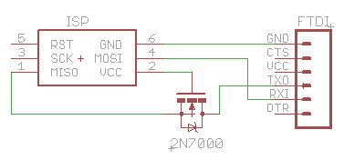
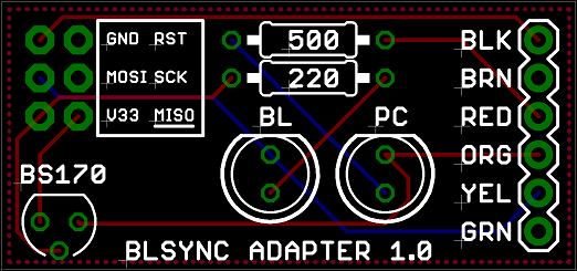
Physically, the blsync adapter is just a passive converter from the 3 x 2 ISP header to a 1 x 6 serial header, with RX connected to MOSI and TX connected to MISO. A MOSFET is used to perform level conversion (thanks Erik!), so either a 5V or 3.3V USB-Serial device can be used. If you know you’ll always be using a 3.3V USB-Serial device, you can omit the MOSFET and connect TX to MISO directly. The 1 x 6 header is designed to work with common USB-Serial devices such as the Adafruit FTDI Friend or Sparkfun FTDI Cable 3.3V.
I also designed a simple blsync adapter board, for a more rugged and permanent solution. It adds a pair of LEDs to indicate Logger and PC activity, but is otherwise the same as the circuit shown above.
Using BLsync
The blsync utility program can retrieve the Logger’s firmware version number, temperature / altitude / pressure graphs, and snapshot list. Data can be saved in CSV format for importing into Excel, or as raw binary.
The blsync utility is configured using command line options:
Usage: blsync -p port [-b speed] [-v] [-c] [-r] [-g filename] [-s filename]
    -p port       Port to use for Logger communication, such as COM1.
    -b speed      Bit rate for communication. Default is 38400.
    -v            Display the Logger firmware version number.
    -c            Save files in CSV format. This is the default.
    -r            Save files in raw binary format instead of CSV.
    -g filename   Sync the graph data, and save it to the named file.
    -s filename   Sync the snapshot data, and save it to the named file.
For example, to sync the temperature, altitude, and pressure graphs from the Logger connected to COM3, and save them in CSV format to the file graphs.csv, the command line would be:
blsync.exe -p COM3 -c -g graphs.csv
By importing the CSV file into your favorite spreadsheet or other analysis program, you can perform whatever analysis you desire on the collected Logger data. A hiker might create a graph showing his friends how high he climbed or how cold it was. A conservationist might use several Loggers to collect data for a study of temperature and pressure at multiple locations within a habitat, and how they relate to observed species observations. Through hardware and software extensions, humidity or other custom sensor data could be collected as well. Because the Backwoods Logger is an open source, open hardware project, the sky’s the limit on what data might be collected and what interesting things might be done with it.
Read 1 comment and join the conversation