

Floppy Emu Display Experiments
Last week I wrote about my troubles with the Nokia 5110 LCD used by Floppy Emu, with a discussion of possible replacements. There was no clearly obvious alternative, as most of the options were too big, too small, too expensive, not available from a reliable supplier, or had some other shortcoming. After some thought, I settled on the 1.3 inch OLED as the most likely alternative. And now, after hacking away on the Emu’s firmware, I have a working example of a Floppy Emu with this 1.3 inch OLED display.
Nokia 5110 Clone LCD: 1.4 inch diagonal display, mounted on a carrier PCB, 84×48 pixels, SPI interface, 1-bit graphics
No-name OLED: 1.3 inch diagonal display, mounted on a carrier PCB, 128×64 pixels, SPI interface, 1-bit graphics
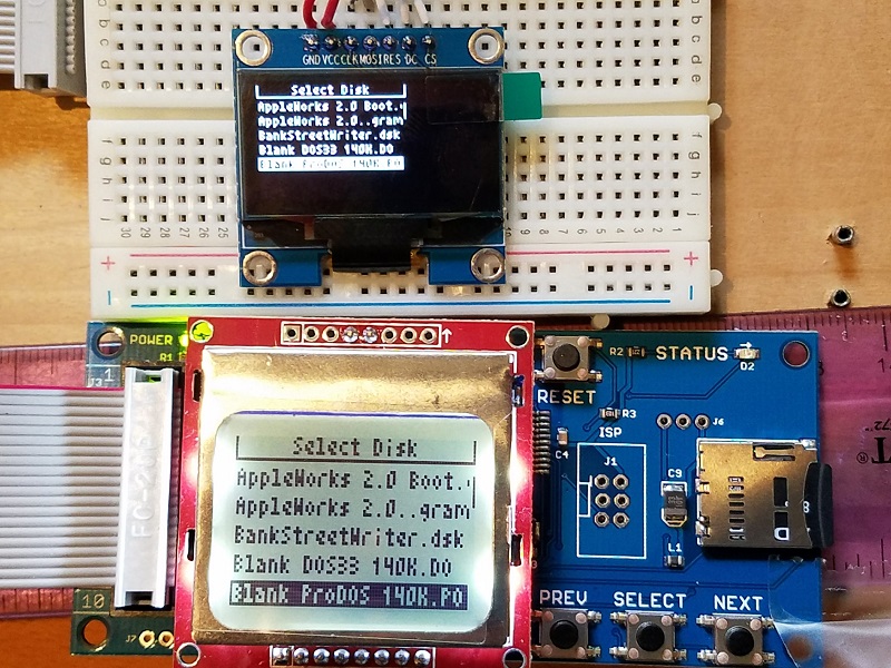
The photo shows a head-to-head comparison between the old and new displays. The picture doesn’t do the OLED justice – although it looks blurry here, it’s actually very crisp and pleasant to look at. The only significant problem is the tiny pixels, which makes the text a bit difficult to read. Although the display diagonal isn’t much smaller than the Nokia LCD (1.3 inch vs 1.4 inch), the aspect ratio is different, and the OLED’s height is only 2/3 the Nokia’s height. Then the OLED packs 1.33x as many vertical pixels as the Nokia, so the OLED actually has 2x as many dots per inch. You can see in the photo, when drawn with the same number of pixels, the OLED text is only half as tall as the Nokia text. Get out your reading glasses.
It’s not too bad, and I could probably live with text this size, but it’s not ideal. It would be great if I could simply make all the text 1.33x taller to take advantage of the OLED’s extra resolution, but unfortunately it’s not that simple. Text needs to be a whole number of pixels tall, and with the Nokia LCD there are six rows of 8 pixel tall text. The most I could increase this with the OLED would be 10 pixel text, 1.25x taller, for 60 pixels total, leaving 4 pixels wasted. But 10 pixel text is an awkward number, because the OLED’s command interface is built around the concept of “pages” that are 8 pixels tall. If text spans a fractional number of pages, I’ll need to completely redo the way display updates are performed, and maintain a framebuffer of the whole display area. Unless I get really fancy (dirty rectangles anyone?), that will require re-sending all 128×64 pixels of the framebuffer to the display every time I draw anything. That will be noticeably slow, which is one of the things I wanted to avoid.
So instead of making the text taller, I’ll probably make it wider. That should help a lot with readability. With 6×8 pixel characters, I’ll get 8 rows of 21 characters each, compared to 6 rows of 21 4×8 pixel characters on the Nokia LCD. Two extra rows of text will be nice.
I still need to look at the power consumption of the OLED as compared to the Nokia LCD. When I have two Floppy Emus powered by a single 5V USB supply, the one with the OLED glitches and resets whenever I turn on the one with the Nokia LCD. I’m not sure what’s causing that, but it doesn’t happen with two Nokia LCDs.
The final hardware headache will be modifying the Floppy Emu PCB layout. In order to keep the OLED centered, I need to relocate the LCD header into a spot that’s currently packed with traces and chips. I’ll also need to move the header from the bottom section of the board to the top (unless I mount the OLED upside-down), which means running several new traces across the full height of the PCB, or just redoing the entire board layout, which doesn’t sound fun. I’ll probably want some kind of mechanical support for the bottom end of the OLED too, since the OLED only has pins along its top, and it tends to hinge downward from those pins by force of gravity. That’s not a deal-breaker, but it looks a bit unattractive.
There will be some software challenges to address as well. I can’t just replace all the Nokia 5110 code with OLED code, because then future versions of the Floppy Emu firmware won’t work on all the Emus out in the world now with Nokia LCDs. I don’t want to maintain two different versions of the firmware either, one for each display type. Ideally I’ll find a way to create a single firmware that knows how to control both types of displays, and can dynamically detect which one is present.
The OLED display costs about twice as much as the Nokia LCD, but it’ll be worth it if it eliminates the headaches I’ve had with the Nokias. Right now I don’t expect I’ll need to change the price of the Floppy Emu. I’ll see how things look once everything is finalized.
Read 7 comments and join the conversation7 Comments so far
Leave a reply. For customer support issues, please use the Customer Support link instead of writing comments.
Ever think about making this project interface-less? This could work a number of ways: simplest would be a numeric 2-digit (or so) LED that denotes selected disk image, and a button (or two) to cycle through them in sequence. More complex would be external control via Bluetooth or Wi-fi (Android/iOS app, web browser on desktop). Less practical but definitely neat would be a classic Mac application with knowledge of the Floppy Emu, which by sending magic codes over the floppy port, could control the behaviour of the device. (of course, every supported platform would need a version of this application)
These might be ridiculous efforts to go to just to avoid having an interface 🙂 But it would interesting as well in opening up the form factor of the device, for instance.
Maybe Maciek is on to something. Maybe allocate one of the serial ports for a two pin interface for a simple command interpreter. Then if someone wants a custom lcd interface, remote control, etc, they can do it themselves. Heck, could even have the mac change the disk though the serial port.
Just a side note, is there a way to send commands to the emulator though the floppy port, kind of like how you send commands normally using the PH0 pins? Just a side project as I was messing with old mac programming:)
Yeah, I’ve been down that line of thought before, and I’m quite happy with a built-in display as a UI solution. I just need to find the right display. I think this 1.3 inch OLED will work and won’t require major hardware changes. The UI alternatives all seem like a big step backwards in usability, or much more work to achieve a similar result.
The Mac floppy driver code doesn’t provide any obvious way to send extra out-of-channel commands to a floppy emulator – I’ve looked. You’d have to bypass the driver, or redefine some drive behavior in a way that would be incompatible with real floppy drives.
> The Mac floppy driver code doesn’t provide any obvious way to send extra out-of-channel commands to a floppy emulator – I’ve looked. You’d have to bypass the driver, or redefine some drive behavior in a way that would be incompatible with real floppy drives.
Ah, so much for that idea then. In-band signalling would still be possible but it’d be significantly harder, and it’d unavoidably be a hack. (ok, I can’t resist! here’s the hack: present a virtual disk image which is actually an interface for controlling the Floppy Emu. Visibility of this interface could be controlled with a hardware toggle, if desired. Double-clicking the disk icon presents an empty folder and files corresponding to every disk image. Dragging a file into the folder causes it to become selected as the active emulated disk. I realize I’ve just described a ridiculous amount of work including implementing most of HFS so not really expecting a serious response, just indulging in handwaving. )
(It’s a shame that there isn’t something analogous to a 3-wire serial connection that would run over Bluetooth and either have a tty interface or a really simple httpd. I could imagine all kinds of uses beyond this project. Oh, well.)
All handwaving aside, I’ve been following your work for years since BMOW itself. I haven’t ordered anything yet but it’s just a matter of time, I’m sure. Keep it up 🙂
I’m just spitballing here but, could you make a adapter pcb for the board you have now? Have headers that are mounted backwards(i.e plastic bit on the top to conserve space) with the metal part sticking downwards to the one on the main board and the opposite for the lcd, like this
https://i.gyazo.com/2dc1a572f55a8863b2c117d28a95fcaa.png
it might work it might not, but if it does you can provide a upgrade pack for all the older BMOW boards.
The target audience for this product (40+ year old nerds like me) might struggle with the smaller display, so definitely do what you can to make it more readable!
Just a thought!
On the flipside, using that tiny font in the comparison picture would allow for longer filenames to be shown and more files on one page.