

Archive for the 'Bit Bucket' Category
Tetris Max and System 6, Fixing 31-Year-Old Bugs
31 years ago Tetris Max for the Macintosh was born, an improved clone of tetris, and it became an insanely popular Mac game during the 1990s. I may or may not have had some involvement in its development. (See lots more Tetris Max history.) Macintosh System 6 was the current OS version at the time of the game’s release, but System 7 was introduced shortly afterwards. It’s recently come to my attention that the final version of Tetris Max (v2.9.1) may not work when running System 6 on certain Mac hardware, even though the game was advertised as System 6 compatible. I haven’t yet been able to fully verify this myself, but there’s a Macintosh Garden bug report from ironboy36 in 2022, and more recently a detailed bug report complete with video (thank you James!) Obviously I need to fix this stuff ASAP – 31-year-old bug be damned. And I need your help! Consider this a group debugging effort.
Both bug reports mention an “Unimplemented Trap” error message, which probably means Tetris Max tried to call a Toolbox function that’s only available in System 7 or later, and isn’t available from System 6. I suspect this bug only applies to color-capable 68K Macintosh models running System 6, because Tetris Max 2.9 works OK under System 6.0.8 on my B&W-only Macintosh SE. That limits the range of Mac models where this problem might appear to the Macintosh II family (including the Mac SE/30), because later Mac models can’t run System 6 anyway, and earlier models (like the Mac Plus and original SE) aren’t color-capable.
James’ test was performed on a Mac SE/30 with the built-in black-and-white screen, running System 6.0.8 loaded from a BMOW Floppy Emu disk emulator. I think he was also using a Mac ROM-inator II replacement ROM during this test. Ironboy36 didn’t mention what hardware was used, so we can only guess.
Reproduction
Challenge #1 is simply reproducing the bug. Unfortunately I think this needs to be done on real hardware, and not under emulation, because I’m not aware of any software that can emulate a color-capable 68K Macintosh running System 6. Mini vMac only emulates non-color Macs like the Plus and SE. Basilisk II can’t handle 24-bit addressing or System 6, and Sheepshaver is PowerPC-only emulation. There’s MESS, but I’m not sure about its capabilities, and setting it up is daunting. [Note: I learned there’s a Macintosh II version of Mini vMac that can handle System 6, but I found it to be slightly unstable and not a reliable testing platform.]
Working on real hardware is OK, even if it’ll be more difficult, but I don’t have easy access to any appropriate machines. My SE/30 needs to be recapped and currently doesn’t boot. I also have a Mac IIci and a Mac IIsi, but one is missing the power supply and the other has an unknown motherboard problem. I can probably get one of those machines working again, but at least for now I need to rely on other people to run Tetris Max with System 6 on systems like these, and send me reports.
Other Complications and Possible Causes
I don’t remember intentionally dropping System 6 support in later versions of Tetris Max, but it’s possible. After 31 years, with no source control and no release notes, I couldn’t tell you exactly what changed between the last few versions of Tetris Max. Version 2.9.1 was the last public release from the 1990s, but the game was later patched to create a 2.9.2x version which supported running directly from a locked disk like the ROM disk provided by the Mac ROM-inator II. And before 2.9.1, there was straight version 2.9, which is the most common version found in archives today. For the purposes of troubleshooting this bug, I think all three versions behave identically.
It’s possible this is actually a Mac ROM-inator II problem, since that’s what James used and possibly ironboy36 too. It would help to try running Tetris Max on the same computer, with the same System version, with the Mac ROM-inator and then again with the stock Apple ROM. Maybe the game is confused into thinking the SE/30 is a IIsi, and then tries to call some System routines that aren’t available in the SE/30? Just a guess.
Another possibility is that the version of 6.0.8 that’s on the Floppy Emu’s SD card is missing some data that’s supposed to be in the System file, and which is actually the source of the problem. For example, I know it’s missing some of the standard bitmap font sizes, though this shouldn’t cause an Unimplemented Trap error. I suspect this particular 6.0.8 System file was borrowed from a Disk Tools floppy rather than being the result of running the full 6.0.8 installer. It would help to try Tetris Max on a Macintosh II series machine with either System 6.0.7, or a fresh install of 6.0.8 from the installer floppies.
Debugging
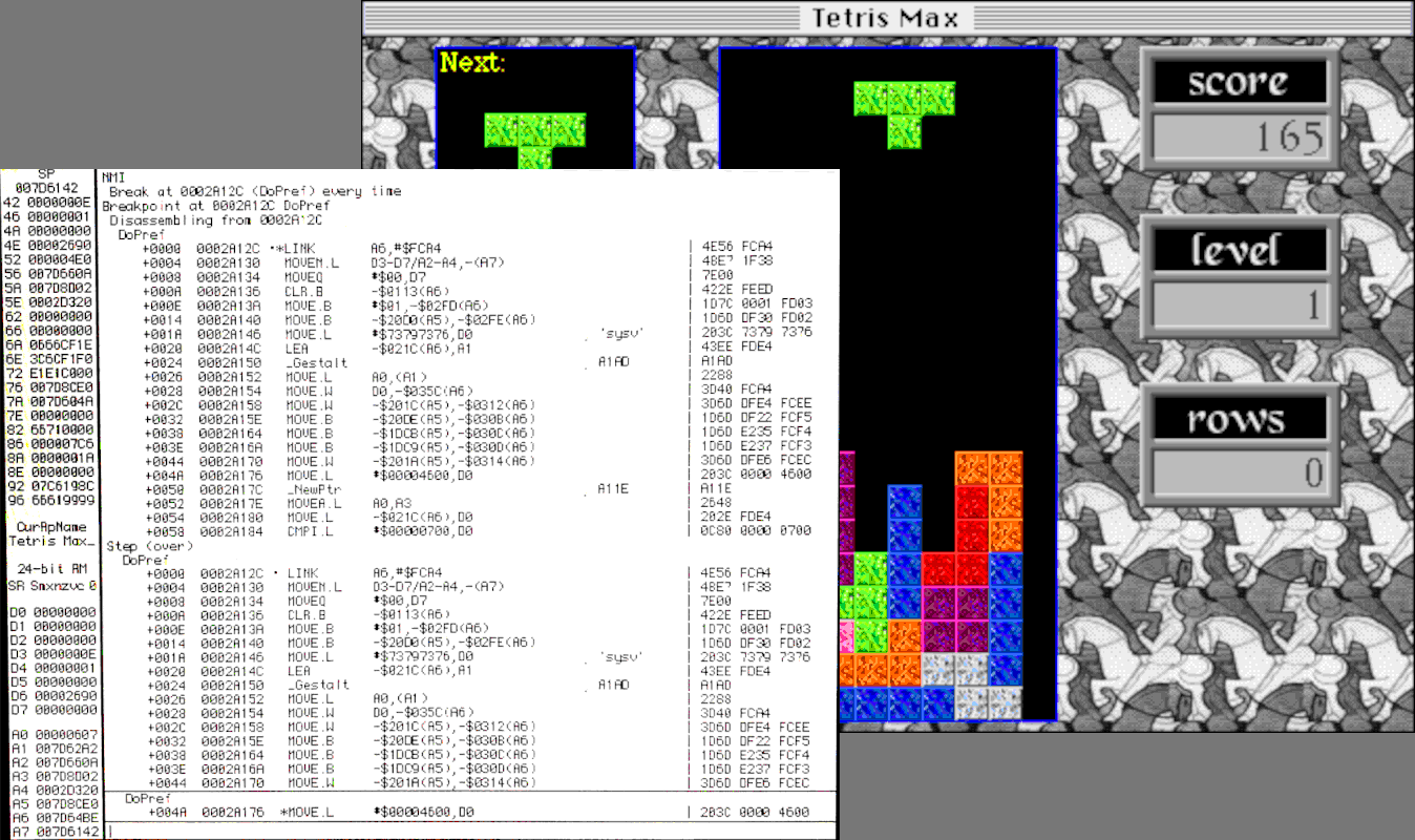
I was able to dig through many layers of dusty old backups, and get Tetris Max rebuilt and running in the debugger with Codewarrior Pro, on an emulated System 9.0 PowerPC Macintosh with Sheepshaver. I stepped through all the code that runs between application launch and when the game window appears, and didn’t see anything that’s obviously System 7-only, but there’s a lot of code and I don’t have a good sense of which OS calls might be to blame. If you’re a developer, you can find the source code at Macintosh Garden.
Ideally I would run Tetris Max in the debugger on a color-capable 68K Mac with System 6.0.8, and go step-by-step until the game crashes, but there are a couple of problems with that approach. The version of Codewarrior Pro that Tetris Max is built with probably doesn’t work under System 6, or on Mac systems as old as the Macintosh II series. Even if it does, I don’t currently have working hardware to do it.
Macintosh Garden also has older versions of Tetris Max, including 2.8, 2.3.1, and older. If I can get the game running on real hardware, or somebody else can try it and report their results, I could find out what version broke the System 6 compatibility. That could provide more clues.
If my ancient memories are correct, someone could also install MacsBug on their Mac, and then they’d get more debugging info when the error occurs, instead of a mostly-useless “unimplemented trap” message. I think MacsBug would report which Toolbox trap the game tried to call, which would be very useful to know.
For the moment, the only viable debugging approach I can think of is to create a series of instrumented builds of Tetris Max, which beep or log their progress to a file during startup, and share these builds with people who can help test. That could eventually narrow down the point of the crash until the offending Toolbox call is identified. From there I could hopefully implement a work-around. But this approach is barely better than inserting PRINT statements into a 1979 BASIC program to aid with debugging, and I don’t like it very much. 30 years later, shouldn’t there be an easier method of debugging?
Read 20 comments and join the conversationReflections on Orders of Magnitude
This week I upgraded my home internet service to 10 Gbps, and not because I needed faster speeds, but because it was simply cheaper than my existing 400 Mbps service. A 25x speed improvement for less money? Yes I’ll take that, thank you! This upgrade started me thinking about how much computer technology has improved over the decades. When I was a kid, I often thought that the most interesting period of technological advancement was 50 or 100 years in the past: when a person could be born into a world of horse-powered transportation and telegraphs, and retire in an era of intercontinental air travel and satellite communications. Yet the changes during my lifetime, when measured as order of magnitude improvements, have been equally amazing.
Processor Speeds – 6000 times faster, about 4 orders of magnitude
The first computer I ever got my hands on was my elementary school’s Apple II, with a 1 MHz 6502 CPU. Compare that to Intel’s Core i9-13900KS, which runs at 6.0 GHz without overclocking, for a nice 6000-fold improvement in clock speed.
Raw GHz (or MHz) is a weak measure of CPU performance, of course. Compared to the 6502 CPU, that Intel i9 has much wider registers, more registers, more complex instructions, superscalar instruction execution, hyperthreading, multiple execution cores, and other fantastic goodies that the MOS designers could scarcely have dreamed of. I’m not sure if there’s any meaningful benchmark that could directly compare these two processors’ performance but it would be an entertaining match-up.
As impressive as a 6000x improvement may be, it’s nothing compared to the improvements in other computer specs.
Main Memory – 1.4 million times larger, about 6 orders of magnitude
In 1983 my family purchased an Atari 800 home computer, with a huge-for-the-time 48 KB of RAM. What’s the modern comparison? Maybe this pre-built gaming PC with 64 GB of RAM? That’s more than a million times larger RAM capacity than my old Atari system, but it’s not even very impressive by today’s standards. Windows 10 Pro theoretically supports up to 2 TB of RAM.
Communication Bandwidth – 33 million times faster, about 7 orders of magnitude
Who doesn’t love a 300 bps modem? It was good enough for getting that Atari system communicating with the wider world, connecting to BBS systems and downloading software. But today’s communication technologies are so much faster, it makes my head spin. What am I ever going to do with 10 Gbps internet service… stream 200 simultaneous 4K videos? Download all of Wikipedia, ten thousand times every day?
To put this in perspective, the amount of data that I can now download in one minute would have needed 68 years with that Atari modem.
External Storage – 182 million times larger, about 8 orders of magnitude
Over the past few decades, the champion of computer spec improvements has undoubtedly been external storage. My Atari 1050 floppy drive supported “enhanced density” floppy disks with 130 KB of data. While that seemed capacious at the time, today a quick Amazon search will turn up standard consumer hard drives with 22 TB storage capacity, for a mind-bending improvement of 182 million times over that floppy disk.
If you’re a vintage computer collector or a BMOW Floppy Emu user, then you’re probably familiar with the fact that the entire library of every Apple II or classic Mac program ever made could fit on a single SD memory card today.
Hardware and Software Cost – 0 orders of magnitude
Despite all these million-fold improvements in computer performance, hardware today still costs about the same as it did 40-some years ago when that Atari system was new. The Atari 800’s launch price in 1979 was $999.95, roughly the same price you’ll pay for a decent Mac or Windows laptop today. The Apple II launched at $1298 in 1977, and the first Macintosh cost $2495 in 1984. In real dollar terms (adjusted for inflation), the cost of computer hardware has actually fallen substantially even while it’s improved a million-fold. That first Macintosh system’s cost is equivalent to $7428 in today’s dollars.
Software prices have also barely budged since the 8-bit days. The first version of VisiCalc (1979) was priced at $100, and today Microsoft Excel is $159. As a kid I mowed lawns to earn enough money to buy $40 Atari and Nintendo games, and today a kid can buy PS5 or Nintendo Switch games for $40. Why? I can’t buy a cheeseburger or a car or a house for 1983 prices, but I can buy the latest installment of the Mario game series for the same price as the original one?
Looking Ahead
If there’s anything I’ve learned from the past, it’s that I stink at predicting the future. Nevertheless, it’s fun to extrapolate the trends of the past 40 years and imagine the computers of 2063, if I’m fortunate enough to live to see them. 40 years from now I look forward to owning a home computer sporting a 36 THz CPU, with 90 petabytes of RAM, a 330 petabyte/sec internet connection, and 3 zettabytes of storage space, which I’ll purchase for $1000.
Read 4 comments and join the conversationOceania Has Always Been at War with Eastasia: Dangers of Generative AI and Knowledge Pollution

In George Orwell’s ominous Novel 1984, the world is controlled by three superpowers fighting a never-ending war. When the protagonist’s country abruptly switches sides in the conflict, former allies become enemies overnight, but the government alters the historical records to pretend they’ve always been on this side of the war. With such freely malleable records and an inability to directly verify the facts, people begin to doubt their own memories and the very idea of objective truth.
How do we know what’s true? Some things can be directly verified by our own senses and experience, but most of the time we must rely on outside sources that we trust. There’s potential danger when pranksters alter Wikipedia entries, or fraudsters publish scientific papers with bogus data, but the truth eventually comes out. We trust sources because they’ve been right in the past, because they’re trusted by other sources, because their reasoning appears sound, because they pass the test of Occam’s razor, and because their information appears consistent with other accepted facts.
The scientific-historical record of accumulating human knowledge has grown steadily for ten thousand years. Yes some information gets lost, some gets proven wrong, some is disputed, and some gets hidden when winners spin the facts to flatter themselves. But despite the system’s flaws, until now it’s worked fairly well to maintain our shared understanding about what’s real and what’s true.
Growth of Knowledge Pollution
How confident can we be that outside sources are correct? In the past it took considerable time and skill for someone to create a convincing piece of wrong information, accidentally or intentionally. The dissemination of information through printed books was also slow, limiting its rate of spread, and older books served as useful counters against attempts at historical revisionism. These factors limited the potential damage from “knowledge pollution”.
Not anymore. Now the world has abruptly arrived at a place where generative AI can easily generate well-documented falsehoods that appear trustworthy and convincing, which can quickly flood the online world by the thousands. Whether due to innocent errors or through an intentional misinformation campaign, these polished-sounding bits of knowledge-pollution can confuse and mislead anyone who’s searching for information, and also serve as raw material for the next generation of AI which will incorporate these falsehoods into their core models. Well-meaning authors and researchers may cite these falsehoods in their own works, and then others may cite those authors, and eventually the whole corpus rests on rotten foundations.
What’s fascinating to me is that as recently as a year ago, virtually nobody was talking about this risk. It wasn’t on anybody’s radar. We worried about AI putting people out of work, or maybe about Skynet. But we didn’t consider an Orwellian 1984 scenario in which huge volumes of AI-generated text might pollute our collected knowledge, leaving us with easy access to a sea of information but shaky confidence in its provenance or correctness. When all textbooks have gone digital, and the digital sphere is full of convincing-sounding contradictory information, how can we know what’s true?
Examples
Perhaps I’m overly paranoid, but there’s plenty of evidence this is already beginning to happen. Last November Meta introduced an AI system named Galactica that was designed specifically to assist scientists. Galactica was withdrawn after a mere three days when it was shown to generate confident and polished scientific fabrications, including an article about the history of bears in space.
Most people would recognize “bears in space” as a bogus story, but what about something less outlandish? My wife’s career is in materials science, and she often writes technical papers related to her work. Recently she used ChatGPT to collect background information for a paper she was writing. After some back-and-forth, she had this exchange:
Another study from 2020, published in the Journal “Nature Sustainability” estimates the embodied carbon emissions of a single semiconductor chip to be around 800-1,000 grams of CO2-equivalent. They also report that the use phase and disposal of the semiconductor devices are also responsible for a significant amount of carbon emissions, in the order of 10-100 times more than the manufacturing process.
can you provide the DOI for the two references above?
J. Clean. Prod. 87 (2015) 523–532. DOI: 10.1016/j.jclepro.2014.10.072
The second reference is: Nature Sustainability volume 3, pages 941–946(2020) DOI: 10.1038/s41893-020-0578-8
Please note that these references are behind paywall, and you might need a subscription to access them.
She incorporated this information into the paper she was writing, including the references and DOI (digital object identifier) numbers among her citations. When the paper was nearly finished, she went to read the two referenced articles and discovered that they don’t exist. The journals are real, but the specific articles are fabrications. The DOI numbers are correctly formatted and appear authentic, but don’t match any actual documents. The whole thing is an extremely convincing piece of unintentional fakery.
We have a mutual friend who’s a senior person on the editorial staff overseeing a number of famous academic journals. She reached out to this friend and shared her story. Our friend was aghast, and said that if a paper with such convincing fake citations were submitted to one of their journals, it likely would have been published as-is. Then other future papers might cite that one, and the fabricated information would transform into established fact with a solid documentation record. They’re now in the process of changing the journals’ editorial controls to address this risk, but it’s unclear how far down the rabbit hole one must go checking citations’ citations ad infinitum.
Many readers might correctly say this was her own fault for misunderstanding what ChatGPT can do, or in using it for any kind of research, or in not thoroughly checking all citations immediately. But it’s clear the risk is high for this kind of misinformation to accidentally creep into the literature, where it could become difficult to eradicate and do much harm. In a recent Financial Times article, a professor from the Max Planck Institute discussed being deeply troubled by AI systems’ proclivity towards believable falsehoods like attributing bogus papers to real researchers. Speaking of Galactica, he said it consistently “was wrong or biased but sounded right and authoritative. I think it’s dangerous.” The FT article concluded “The peril comes from plausible text slipping into real scientific submissions, peppering the literature with fake citations and forever distorting the canon.”
It’s not just scientific literature at risk either. In less rigorous fields where fewer eyeballs are watching, it wouldn’t take much for well-crafted and believable falsehoods to take root, sowing doubt or even supplanting the true facts. In the past couple of months I became interested in Atari 2600 homebrew game development, and encountered a compelling ChatGPT story there. Andrew Davie is a well-known and prolific author of modern 2600 homebrew games, and he asked ChatGPT about himself:
Davie began his career as a video game programmer in the 1970s and 1980, creating games for the Atari 2600 and other early home video game consoles. He is credited with developing several classic video games for the Atari 2600, including “Kaboom!”, “Basketbrawl”, and “Miner 2049er”.
Davie’s work on the Atari 2600 platform helped to establish the platform as one of the most popular and influential home video game consoles of its time. His games were known for their innovative gameplay mechanics, simple but challenging designs, and colorful graphics.
In addition to his work on the Atari 2600, Davie has also contributed to the development of other classic video games, including games for the Commodore 64 and Apple II. He is widely regarded as one of the pioneers of the classic video gaming industry, and his contributions have helped to shape the direction of the industry as we know it today.
Andrew Davie continues to be active in the classic video gaming community, and his work continues to be appreciated and respected by gamers and video game enthusiasts around the world.
This is a great biography, well-written, and including lots of good contextual information. It’s also almost entirely wrong. But few people outside this small Atari hobby would recognize the information as wrong, and even many people in the hobby wouldn’t realize it was a fabrication. Just by including the text here on my blog, which enjoys a decent reputation and page rank, I’m giving this fabrication legitimacy and increasing the chances it will be used as “truth” during the training of some future AI or digitally-generated encyclopedia. It gives me a sinking feeling to imagine this kind of distortion multiplied a thousand-fold and extrapolated into the future.
Prevention
Is there anything we can do to prevent this kind of knowledge pollution? I’m not sure. It’s too late to put this particular genie back in the bottle, so we’ll need to find methods of coping with it.
There’s been plenty of discussion about automated techniques for identifying AI-generated text. OpenAI is reportedly working on a watermark of sorts, where a particular pattern of sentence structure and punctuation can be used to identify text from its AI model. But this seems like a weak tool, which could be defeated by a few human edits to AI-generated text, or by simply using an AI from a different vendor. Additional researchers are developing AIs that try to identify other AI-generated text.
I’m unsure what technical measures could realistically prevent future knowledge pollution of the type described here, but there may be more hope for preserving existing knowledge against future revisionism, such as sowing doubt that moon landings ever occurred. I would imagine that digital signatures or blockchain techniques could be used to safeguard existing collections of knowledge. For example we might compute the hash function of the entire Encyclopedia Britannica and publish it widely, to make that particular encyclopedia resistant to any future pollution along the lines of “we’ve always been at war with Eastasia”.
If technical measures fail, maybe social ones might succeed? Advice like “don’t believe everything you read” seems relevant here. People must be trained to think critically and develop a healthy sense of skepticism. But I fear that this approach might lead to just as much confusion as blindly accepting everything. After all, even if we don’t believe everything we read, we need to believe most of what we read, since it’s impractical or impossible to verify everything ourselves. If we treat every single piece of information in our lives as suspect and potentially bogus, we may fall into a world where once-authoritative sources lose all credibility and nobody can agree on anything. In recent years the world has already traveled some distance down this path, as simple records and data become politicized. A broad AI-driven disbelief of all science and history would accelerate this damaging trend.
It’s fashionable to conclude essays like this with “Surprise! This entire article was actually written by ChatGPT!” But not this time. Readers will need to suffer through these paragraphs as they emerged from my squishy human brain. I’m curious to know what you think of all this, and where things are likely to head next. Please leave your feedback in the comments section.
Read 13 comments and join the conversationAtari 2600 Hardware Acceleration
Atari 2600 programming techniques are fascinating. The hardware is so very limited, and programmers must use every possible trick to scrimp and save the last CPU cycle and byte of RAM. For a refresher on the 2600 hardware, check out my previous Atari overview. The console’s longevity is remarkable, with new games and demos still being produced today – over 100 new titles last year alone. The quest for the ultimate Atari 2600 programming techniques has continued all this time, in order to wring out maximum performance.
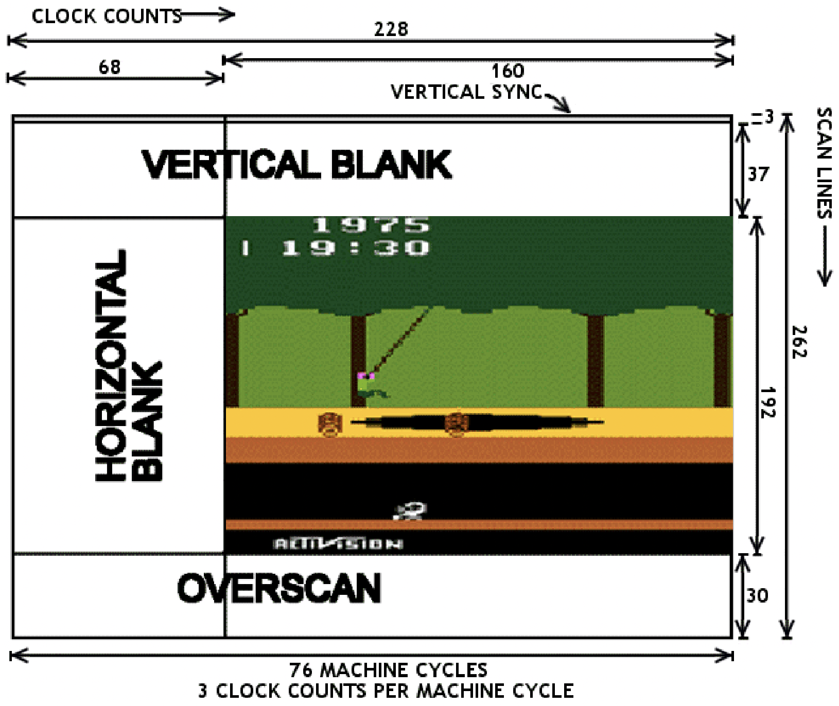
Atari programming requires racing the beam, updating graphics registers just before the instant they’ll be used to paint the next pixels on the current scan line. With only 76 CPU cycles per scan line, there just isn’t enough time for the poor 6502 to do very much. Want to update the foreground color multiple times at different horizontal positions? OK, but there might not be enough time remaining to also update the pixel bitmap during the scan line, or set the sprite positions. It’s a series of difficult tradeoffs and code optimization puzzles.
More Hardware Makes Things Better?
To create better-performing Atari games, programmers may need to think outside the box – literally. The 2600 console consists of a 6502 CPU (actually a 6507), a 6532 RIOT, and an Atari custom graphics chip called TIA. But what about the game cartridge? What’s inside that? The Atari’s designers envisioned cartridges as simple 4KB ROMs in a protective plastic shell, but there’s no reason aside from cost why there couldn’t be other hardware inside a cartridge too.
Within a few years after the Atari’s 1977 release, game publishers began including a small amount of 7400-type glue logic or a simple PLD inside game cartridges, in order to assist with bank switching. The Atari only provides 4KB of address space for game cartridges, but with this extra hardware inside, publishers were able to make 8KB and 16KB games using custom bank-switching schemes. Some later cartridges also included additional RAM to augment the paltry 128 bytes available in the Atari. This provided more storage space to create larger games, but didn’t help improve the Atari’s CPU or graphics performance.
Pitfall II and the DPC Coprocessor
Activision’s Pitfall was one of the most popular games for the Atari 2600. For the sequel Pitfall II, expectations were high, and the game’s designer David Crane did something that had never been done before: put a full-blown coprocessor inside the game cartridge. Crane’s DPC (Display Processor Chip) added two additional hardware sound channels, a music sequencing capability, a hardware random number generator, and a graphics streaming capability with built-in options for masking, reversing, or swizzling the bits.
That’s an appealing collection of features, but the graphics streaming capability is probably the most interesting. To understand how it can help improve graphics performance, let’s first look at some hypothetical code without DPC. Imagine that the game code wants to read bytes from a graphics table in ROM and stuff them into the TIA’s GRP0 register (the pixel bitmap for sprite 0) as quickly as possible, in order to create different patterns at points on the scan line. The code might look like this:
; setup

lda #>DrawData  ; an address in ROM

sta GfxPtr      ; a pointer in RAM page 0

lda #<DrawData

sta GfxPtr+1
; kernel

lda (GfxPtr),X  ; 5

sta GRP0         ; 3

inx              ; 2

lda (GfxPtr),X  ; 5

sta GRP0         ; 3

inx              ; 2

lda (GfxPtr),X  ; 5

sta GRP0         ; 3
This requires a total of 10 CPU cycles for every repetition of read, write, and increment of the index register. During those 10 CPU cycles, the electron beam will move 30 pixels horizontally, so in this example it would only be possible to update the pixel bitmap every 30 pixels. This limits the number of objects or patterns that can be displayed in the same horizontal row of the screen.
The DPC provides some extensions to speed up this process. From my study of the chip, it works like this:
- Writing to a special pair of addresses in the cartridge’s address space will set up a graphics stream pointer
- Reading from a special address will return the next byte from the stream pointer, and increment the pointer
Using the DPC, the previous example could be rewritten something like this:
; setup

lda #>DrawData  ; an address in ROM

sta BytePtr     ; special addr in cartridge address space

lda #<DrawData

sta BytePtr+1
; kernel

lda NextByte    ; 4 - special addr in cartridge address space

sta GRP0         ; 3

lda NextByte    ; 4

sta GRP0         ; 3

lda NextByte    ; 4

sta GRP0         ; 3
This reduces the total number of CPU cycles for every repetition from 10 down to 7, enabling the pixel bitmap to be updated every 21 pixels instead of only every 30 pixels – quite a nice improvement.
Pitfall II was released in 1984. Despite the major effort that doubtless went into designing the DPC chip, Pitfall II was the only game to ever use it. No other Atari 2600 games from the original Atari era 1977-1992 ever included a DPC or other coprocessor. The DPC was an impressive one-off, and remained the pinnacle of Atari 2600 hardware acceleration tech for 25 years, until rising interest in retrogaming eventually rekindled interest in the Atari console.
21st-Century Hardware
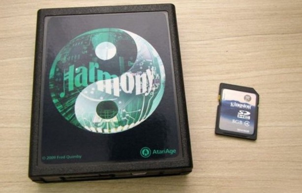
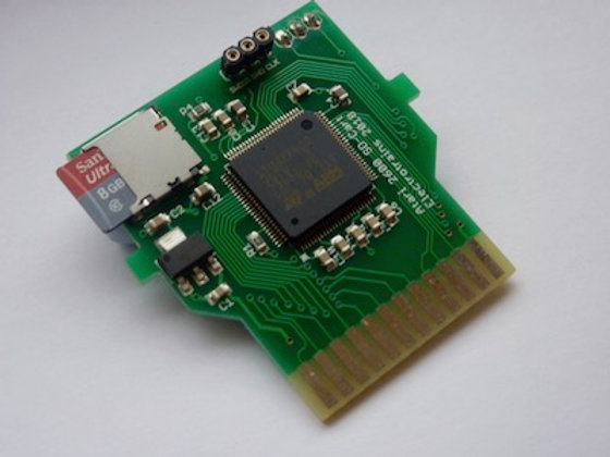
The Harmony Cartridge for Atari 2600 was first released in 2009. Harmony is a bit like my BMOW Floppy Emu Disk Emulator, but for Atari game cartridges instead of Apple floppy disks. Inside the cartridge is an ARM microcontroller and an SD card reader, and the hardware loads Atari game ROMs from the SD card and then emulates a standard ROM chip, including any necessary bank switching logic or extra RAM that may have existed in the original game cartridge.
The original function of Harmony was simply to be a multi-ROM cartridge, but for Pitfall II, Harmony’s designer was also able to use the ARM microcontroller to emulate David Crane’s DPC chip. Before long, he and a few collaborators began to share ideas for a new coprocessor design, like DPC but even more powerful, and emulated by Harmony’s ARM chip. While this wouldn’t do anything to benefit the library of original Atari games, it would open up new possibilities for the active community of Atari 2600 homebrew game developers. The coprocessor design they eventually created is called DPC+.
I haven’t looked at DPC+ in detail, so I may be misstating the specifics, but I’ve seen three features that look particularly interesting.
FastFetch – Atari programs often include time-critical sequences that load a byte from zero page RAM (3 CPU cycles), write the byte to a TIA register (3 CPU cycles), and repeat. Six total CPU cycles per iteration. For drawing fixed graphics patterns, the load from zero page RAM can be replaced with a load of an immediate value into a register, which reduces the total to five clock cycles but means the graphics data must a constant. That constant value is part of the program, which is stored in ROM, which is emulated by the Harmony cartridge. Harmony is able to perform a bit of trickery here, so when the program performs an immediate load of the constant value, Harmony actually supplies data from the graphics stream instead. This makes it possible to draw dynamic graphics data while still enjoying the five-cycle performance of drawing constant graphics data.
Bus Stuffing – The data bus output drivers on the NMOS 6502 (and 6507) chip are non-symmetric. They drive logical 0 bits strongly to near 0 volts, but logical 1 bits use a weak pull-up to 5 volts. If the CPU is outputting a 1 on the data bus, external hardware can safely overdrive the bus with a 0 without damaging the CPU – something that would be dangerous with a symmetric push-pull output driver. For time-critical code loops, Harmony uses this technique to eliminate CPU graphics data reads entirely. The CPU program just performs a long series of write instructions, repeatedly writing the value $FF (binary 11111111) to TIA registers, while Harmony pulls down the appropriate data bus lines to create the next byte of the graphics stream. This reduces the number of CPU cycles needed per iteration to a mere three cycles.
ARM Code Execution (ACE) – Still not fast enough? Harmony also enables the Atari’s 6502 program to upload and execute arbitrary code on Harmony’s 32-bit 70 MHz ARM microcontroller. Compared to the 8-bit 6502 running at 1 MHz, that’s a dramatic performance improvement for compute-heavy code.
Aside from DPC+, Harmony also supports other coprocessor models called CDF and CDFJ, which are further extensions of DPC+. I haven’t looked at these.
Harmony is no longer the only player in this space, and since 2018 some interesting alternatives have appeared. UnoCart 2600 is conceptually very similar to Harmony, but is open source and uses a more capable microcontroller. To my understanding, UnoCart 2600 supports bus stuffing and ACE, although ACE code for Harmony isn’t directly compatible with the UnoCart 2600 due to the differing memory maps of the microcontrollers on the two cartridges. UnoCart 2600 does not support other DPC+ extensions, which I think is because Harmony is a closed source design and its maintainers have chosen not to share the tech details needed for DPC+ emulation. Most recently and intriguingly, PlusCart has appeared as an UnoCart 2600 spin-off that loads game ROMs over WiFi instead of from an SD card. It’s the golden age of retro-Atari products.
When is an Atari no longer an Atari?
Thanks to Harmony and similar devices, within roughly the past 10 years, there has emerged a large and growing library of “hardware accelerated” homebrew Atari games. With the extra support of the coprocessor in the Harmony or UnoCart cartridge, these games are able to create graphics and sound that are much more impressive than anything that was possible back in the 1980s.
This all leads to the question I’ve been grappling with. When an Atari 2600 game console from 1977 is hot-rodded with a 32-bit coprocessor running at 100+ MHz, is it still an Atari 2600? Should games that target this augmented hardware still be considered Atari 2600 games?
Here’s my small editorial. There are no right or wrong answers about this, and everyone should be encouraged to do whatever they find to be most fun. From a technical standpoint I find Harmony and its siblings to be impressively clever, fascinating to study, and I wish I’d thought of these ideas myself. And the multi-ROM cartridge capability is extremely convenient for any modern game collector who doesn’t want to store hundreds of physical game cartridges.
As for the DPC+ coprocessor and similar hardware acceleration extensions, they make me feel… conflicted? Uneasy? When it comes to retrocomputing, I’m something of a hardware purist. For me, the appeal of the Atari 2600 comes from trying to make the most out of its limited hardware capabilities. By adding new 21st-century hardware with new performance-enhancing capabilities, it’s effectively moving the goalposts. I can compare two Atari games that target the original hardware, and if the first game looks visually more impressive than the second, I’ll know the first programmer did a better job. But if one of the games uses a coprocessor with extra hardware capabilities, then it’s no longer a fair comparison. Eventually I hope to try writing my own Atari game, and I’ll probably target the original hardware without any coprocessor extensions, so that I can fairly compare my efforts against the classic Atari games of the 1980s.
Read 8 comments and join the conversationThoughts on an Apple II FPGA Coprocessor
I’ve been kicking around the idea of using the on-board FPGA in my Yellowstone Universal Disk Controller as a general-purpose Apple II coprocessor. With an FPGA on a peripheral card connected to the 6502 address and data buses, I can’t make the CPU run any faster, but maybe I can make calculations faster by offloading them to some type of coprocessor that’s constructed within the FPGA. As a simple example, I could implement a fast PicoBlaze soft-CPU or something similar, and provide a way for the 6502 to run/halt the PicoBlaze and read/write from its memory space. The 6502 could upload a short PicoBlaze program and its required data, wait for the PicoBlaze to finish running, and then read the results back out.
The existing Yellowstone hardware can already do this. It would just be a matter of firmware development.
What would this be useful for? I’m not sure. But the Yellowstone firmware already implements a very simple taste of this idea, because I needed it in order to achieve the disk timing requirements. It’s not a coprocessor, but it’s an extension that shaves a few clock cycles where they’re most valuable. There’s a specific magic address in the Yellowstone card’s address space, and when the 6502 reads from that address, Yellowstone performs automatic GCR decoding of the most recent disk byte.
I had a crazy idea to use this like a classic computer hardware emulator, except that the Apple II wouldn’t be emulating an older computer but a newer one. The 6502 program could just sit in a tight loop reading bytes from the FPGA coprocessor and writing them into the Apple II frame buffer, so whatever appeared on the screen would be the result of the coprocessor program. It would still be limited by the Apple’s physical screen resolution and color palette, but panning around a larger virtual screen should be possible. And conveniently I’ve already implemented a Macintosh Plus FPGA core, so in theory we could see MacOS running on an Apple II? Or more realistically, this scheme could turn an Apple II into something like a Commodore 64, or a 1980s video game console. Probably impractical for any serious use, but at least it would make interesting discussion for r/vintagecomputing!
Read 9 comments and join the conversationAtari 2600 Hardware Design: Making Something out of (Almost) Nothing
Atari Combat, 1977
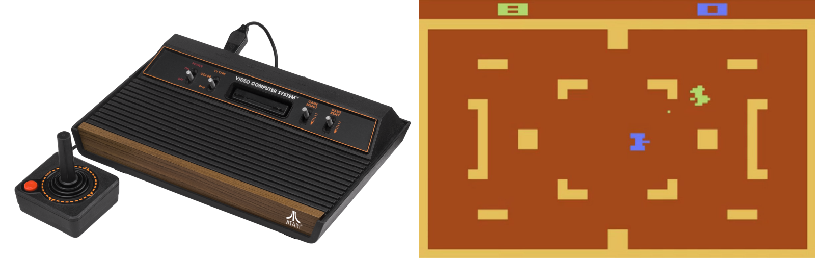
The Atari 2600 wasn’t the first home video game console with replaceable games, but it was the first to be widely successful. Introduced in 1977 as the Atari VCS (Video Computer System), and later renamed Atari 2600 in 1982, it eventually sold over 30 million units and established a new market that still endures today in the PlayStation and Xbox. Prior to the 2600, most video game systems were either coin-operated machines found in bars, or fixed-function devices limited to a few built-in games like Pong. Atari’s first home system was the beginning of a new age.
This wood-grained block of electronics preoccupied my young mind. I wanted one badly, but never succeeded at convincing my parents. I was eleven years old in 1982 when my friend Fred got an Atari, and I was sick with jealousy:
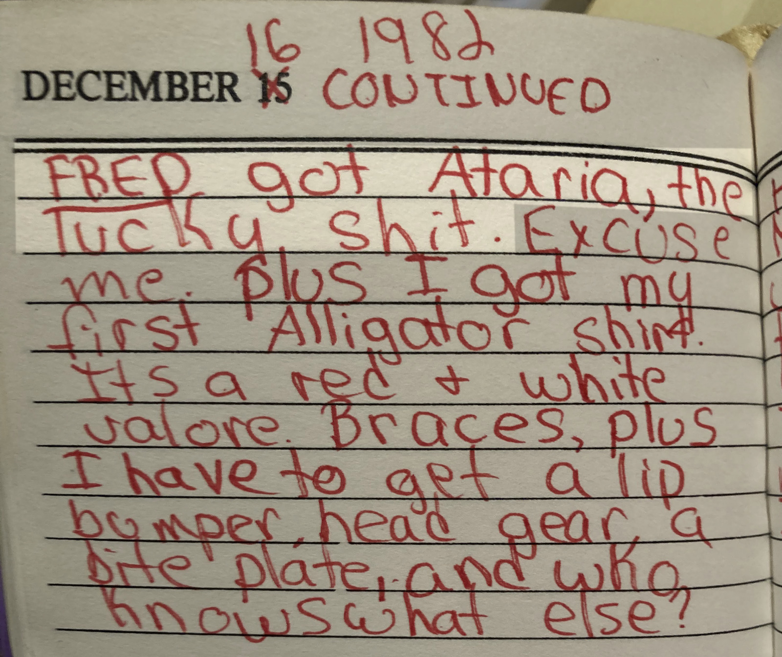
December 16 1982, arrival of Ataria (sic)
What a day! Not only did Fred get an Atari system, but I got braces and an Izod Lacoste alligator shirt.
Atari 2600 Hardware Overview
Recently over the holiday break, I became interested in the 2600’s hardware architecture and started reading everything that I could find about it. I knew that it was some kind of 6502-based system, and I’d heard mentions of “racing the beam”, but that’s as far as my knowledge went. I was shocked to discover how primitive the 2600 hardware was, even compared to contemporary 6502 systems like the Apple II, Commodore PET, and even Atari’s own 8-bit computers.
Inside that wood-grained box there were only three digital chips:
- 6507 CPU (pin-reduced version of the 6502)
- 6532 RIOT
- TIA (Atari custom IC)
Notably absent from this list was any RAM or ROM! The ROM came from whatever game cartridge was inserted – there was absolutely no built-in I/O helper routines or operating system, so it was up to the game programmer to provide everything. Game cartridges were limited to 4 KB and many early games were only 2 KB. Any of the photos on this page are vastly bigger than that.
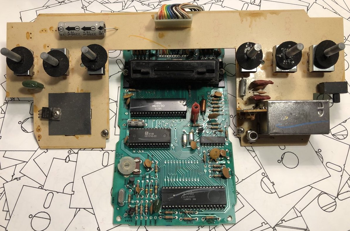
early version of Atari VCS circuit board
RAM was limited to the tiny amount of storage space built-into the 6532 RIOT chip – just 128 bytes. 128 bytes! That is… I don’t even… that is small. Like really, really small. I might have guessed 1 KB or 2 KB RAM, but 128 bytes is just in another category entirely. What’s worse, this tiny amount of RAM had to serve as both the scratchpad/heap and as the stack! Programmers got a few bytes for things like player and item locations, strength, score, and that’s all.
But hold on, because it was even worse than you think. This pin-reduced 6507 eliminated the 6502’s NMI and IRQ pins, so there was no hardware interrupt capability at all. Everything had to be accomplished with software timing and polling. For a real-time system built around the concept of racing the beam, this was just masochism.
And for the final kick in the nuts, there was no framebuffer. There wasn’t even a line buffer. The programmer only had a few TIA registers to play with and nothing more. Most graphics had to be generated by the CPU on the fly, at the very moment that the television’s electron beam was scanning past the pixels of interest. Even the VSYNC signal for the television had to be handled in software. With hardware like this, I’m surprised the Atari 2600 didn’t require a coal-fired steam engine or a wooden crank handle to boot the games! It’s crazy. I love it.
Inside the TIA Chip
The heart of the 2600 is Atari’s custom-designed TIA chip – the Television Interface Adapter. You can find the hand-drawn TIA schematics on the web if you’re curious how it works. The TIA internals look very strange to modern eyes, beginning with the extensive use of linear feedback shift registers where you would expect to find binary counters, for things like the horizontal sync counter or the sprite position registers. I’ve seen LFSRs used as random number generators in other 8-bit designs, but never as a general-purpose counter. These LFSRs also use two separate clocks, 180 degrees out of phase, which seems equally strange. Here’s the six bit horizontal sync counter:
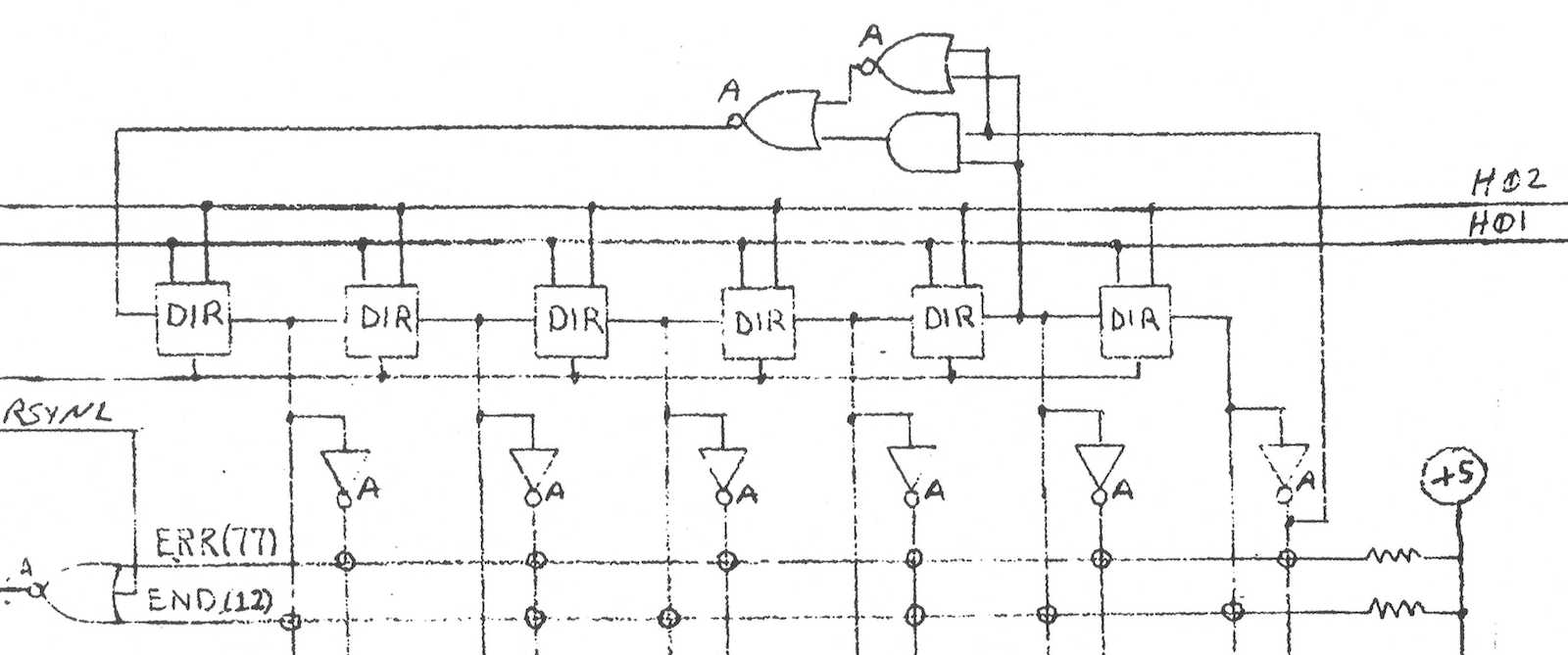
The chip designers must have had their reasons: maybe LFSRs were cheaper to implement or required fewer transistors than regular binary counters? If you just need a six bit counter, then ultimately it doesn’t really matter if it counts 64 states from 000000 sequentially up to 111111, or if it follows some other random-looking but deterministic sequence of states. Either way you can add logic to check for the terminal state and reset the counter when needed. If anyone has an idea why the TIA’s designers used LFSRs for this stuff, I’d love to hear about it. Fortunately the Atari 2600 programmer is mostly insulated from this LFSR funny business.
So how do games actually draw stuff? The simplest place to begin is with what Atari calls the playfield, and is effectively a background pattern on the screen. The TIA has 20 bits of register state which the programmer can modify, and which is used to create a one-dimensional low-resolution monochrome bitmap on the left half of the scan line. The right half of the line is either a copy of the left, or a mirrored copy. Want something completely different on the right side? Too bad. Want multiple colors? Too bad. The same 20 bits of playfield register state are used on every horizontal scan line, too. Want to display something different on each line? That requires constantly modifying the playfield registers, before each new scan line is drawn. There are only 76 CPU clock cycles during each scan line, and with most CPU instructions requiring 2 to 5 clock cycles, that doesn’t leave much time to do… basically anything.
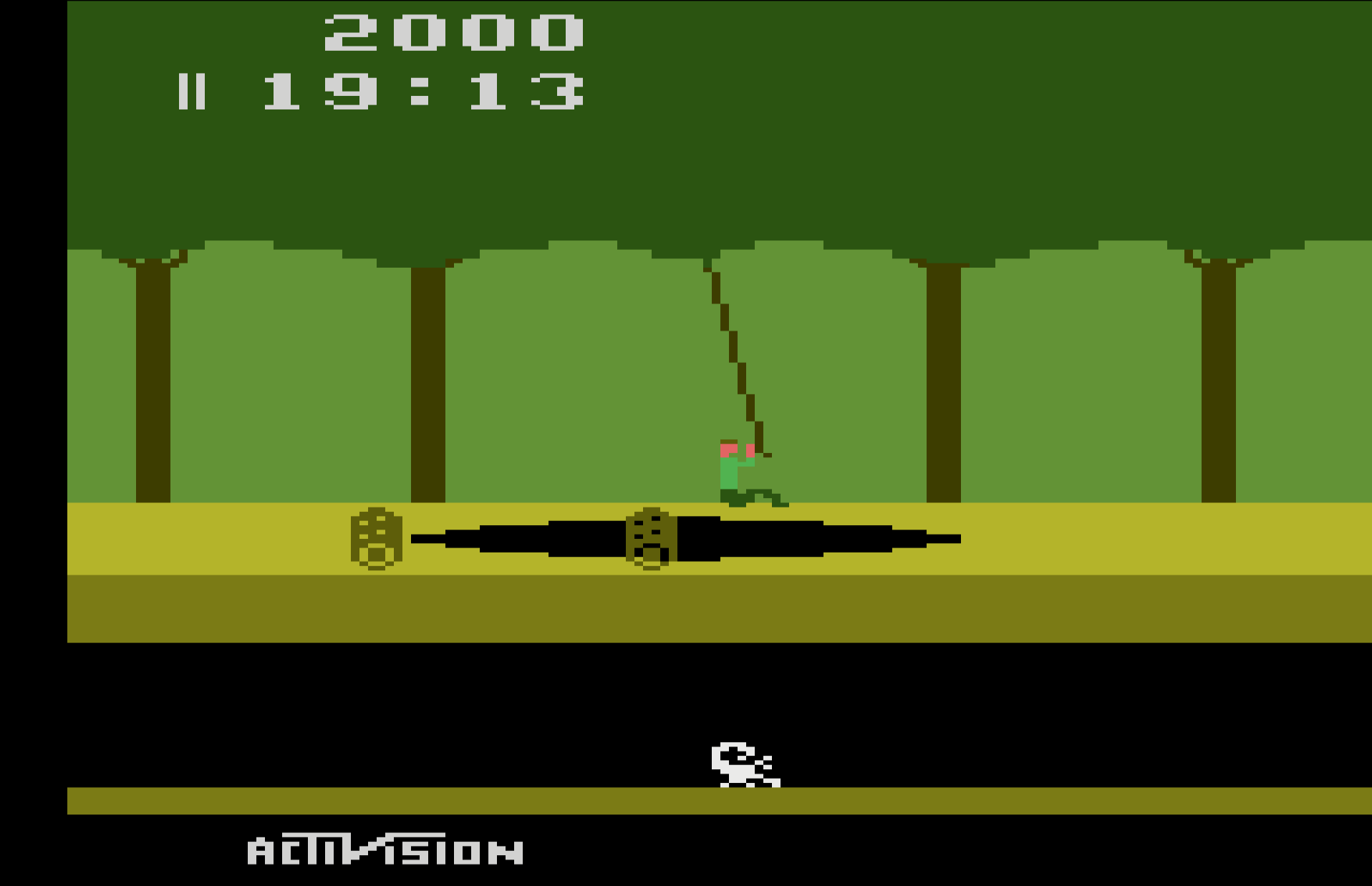
This playfield behavior explains why so many Atari games have left-right symmetry in their backgrounds, walls, or similar content. Look at this image of Pitfall, and notice how the tree canopy, tree trunks, ground, pit, and underground cave all show left-right symmetry. These are all built from the playfield (plus additional tricks to be described later). The only sprites are Pitfall Harry, the vine he’s swinging from, the rolling log, and the scorpion.
What about those sprites? Atari called them players and missiles, but the concept is the same. Players are sprites eight bits wide, and the pixels are smaller than playfield pixels. They can be positioned anywhere on the scan line, but like the playfield, they’re one-dimensional monochrome bitmaps. If the programmer wants 2D sprites (which they certainly do), then the code must constantly modify the player graphics register, updating it before each new scan line is drawn, including setting the register to zero for the areas above and below the player sprite where nothing should be drawn. Does that sound incredibly tedious? You bet!
Missiles are only one bit wide instead of eight, but are otherwise identical to players. The TIA provides two players, two missiles, and a ball that’s like a third missile. If the programmer wants more sprites than this, or wants multi-colored sprites, or anything else that the hardware doesn’t provide, then they’ll need to get fancy by combining multiple players and missiles, or else make lots of precisely-timed updates to the TIA registers to create the illusion of additional sprites and colors.
One common technique was to design games with distinct horizontal bands of activity, like Pitfall here. That allowed the same player sprite to be reused multiple times as the screen was painted from top to bottom. For Pitfall, player 0 might first be used to draw a score digit at the top of the screen. Then the same player 0 hardware resource would be used to draw part of Pitfall Harry, then to draw the rolling log, and finally to draw the scorpion. Since none of these overlapped each other horizontally, there was no conflict as long as the software could update the player graphics and position quickly between scan lines.
Atari Hardware Tricks
Under a one-dimensional hardware system like this one, collision detection would have been extremely difficult if it were left up to the software to provide. The necessary degree of bookkeeping would be too much: checking all the sprites and the playfield for collisions with each other would be virtually impossible with only 76 clock cycles per scan line, on top of all the CPU’s other critical tasks. Fortunately the TIA provides the very cool feature of hardware collision detection, at the pixel level! Any time a non-zero pixel overlaps another non-zero pixel of the playfield, a player, a missile, or the ball, a corresponding collision bit is set in the TIA, which software can later check and clear. With a total of six graphics objects there are (6*5)/2 = 15 possible collisions (an application of the Handshake Problem) to be tracked by the TIA. Nice!
Horizontal positioning of players and missiles is notoriously difficult. Most programmers would expect that the TIA has registers to specify the horizontal position of each sprite, but no. That would be too easy. On the Atari 2600, the horizontal position of a player or missile is set by writing to a special TIA register at the exact moment the electron beam passes the desired position. Think about that for a minute. The specific value that’s written to the register doesn’t matter. The program isn’t telling the TIA “put player 0 at position X”, it’s telling the TIA “put player 0 at… (wait for it) RIGHT HERE!” Thanks to this design, horizontal positioning requires synchronizing a software loop to the start of a scan line, delaying some amount of time dependent on the desired horizontal position, and then writing to the TIA register. Rather than setting a specific value for the horizontal position, the software is actually resetting one of those LFSRs in the TIA.
With the standard technique for this timing-based horizontal positioning, it’s only possible to get a horizontal resolution of five CPU clock cycles, which is equivalent to 15 pixels. To help the programmer get fine-grained control, the TIA provides additional registers that enable each sprite to be adjusted between -8 to +7 pixels from its ordinary position. It’s clumsy, but the combination of timing-based positioning plus fine-grained adjustments enable sprites to be positioned at any horizontal coordinate.
The fine-grained horizontal control involves writing to a TIA register named HMOVE, and its use leads to one of the Atari 2600’s most notorious graphical flaws: an irregular series of black lines on the left side of the screen, obscuring part of the playfield. This is often called the HMOVE comb. Here’s an example from Space Invaders:
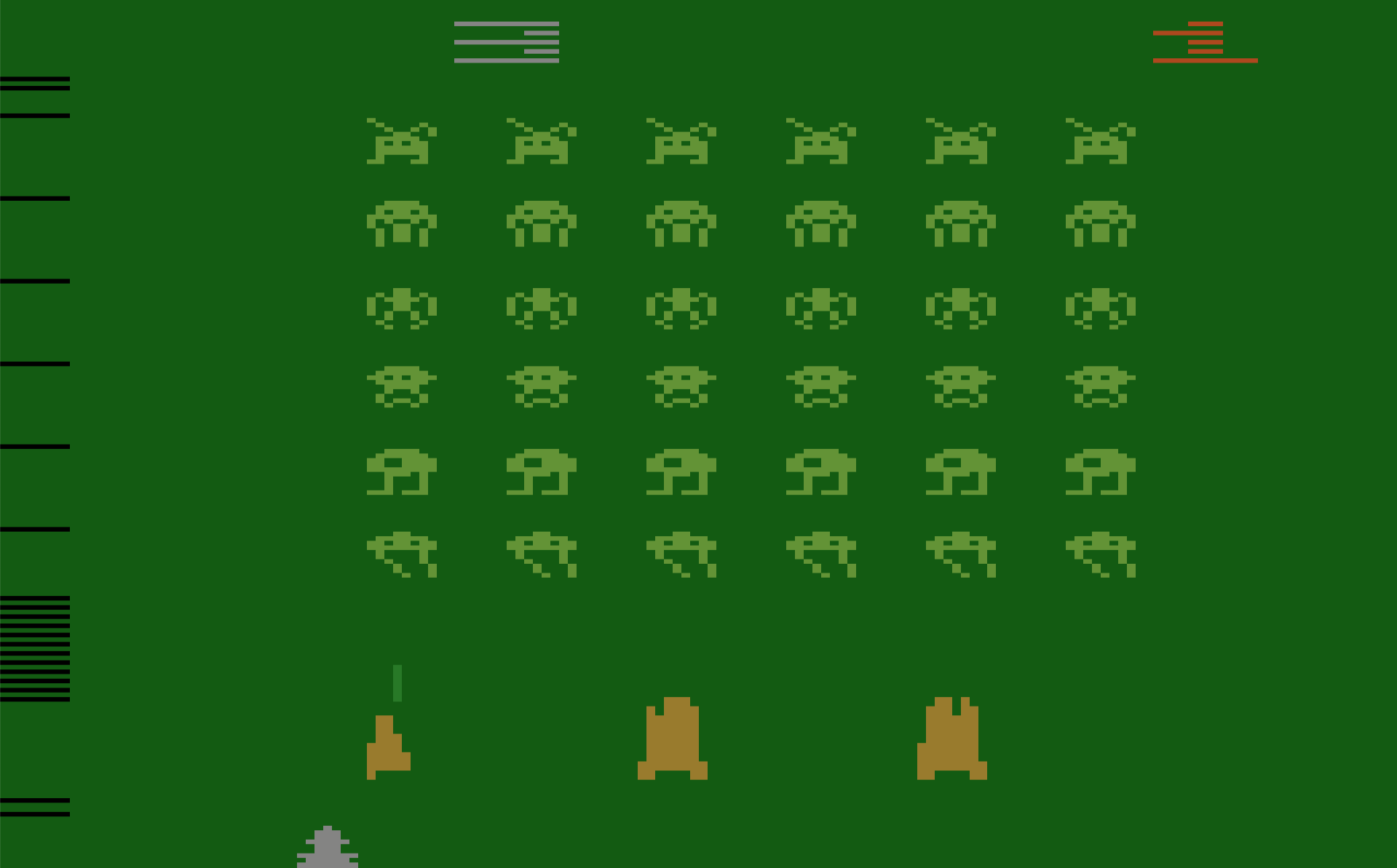
This is a side-effect of the way the TIA performs fine-grained adjustment of sprite positions, and many games exhibit this problem. Any time HMOVE is written to during a scan line, the horizontal blanking interval will be extended by eight pixels on that line, cutting off the left edge of the line. Is it a bug? An unintended feature? The exact details are much too complex to describe here, but Andrew Towers has written a very thorough explanation of TIA behavior which you’ll find at http://www.atarihq.com/danb/files/TIA_HW_Notes.txt. See the heading Playing with the HMOVE Registers.
Why do only some games display this HMOVE comb effect, and others apparently don’t? It only appears when games reuse the same sprite at different vertical positions on the screen, which requires adjusting the sprite’s horizontal position mid-frame. Space Invaders does this extensively, but simple games like Combat don’t do this. Combat is limited to the two built-in players and two built-in missiles, with no mid-frame repositioning, and therefore no HMOVE comb.
Pitfall takes a different approach, with a solid black bar at the left edge of the screen instead of a comb. This is the result of writing to HMOVE on every scan line, even when it’s not needed. Activision used this technique in many games, apparently having concluded that a solid black bar looked nicer than a partial black comb.
There are many more software tricks necessary for creating a high-quality Atari game. A non-symmetrical playfield or multi-colored playfield can be created by modifying the playfield graphics and color registers at precisely the right times, but it’s not easy! Color registers can also be modified between lines, to provide more total colors on the screen even when the number of colors on a single line is limited. Sprites can be reused and repositioned at different vertical positions, or can even be reused at the same vertical position with careful timing and attention to TIA behavior. Atari 2600 programming is a very deep topic, and it’s a long journey from bouncing ball demos to a high-quality game like Pitfall.
Atari 2600 Development Today
Want to try your hand at writing some Atari game demos? Yes you do, and it’s much easier today than it was in 1977. Start with this Atari 2600 Programming for Newbies tutorial written by Andrew Davies. Software is written in 6502 assembly language, and if you’re reading this blog, then there’s a good chance you already know it. To assemble your software, use DASM, a venerable and feature-filled cross-platform assembler for the 6502 and other 8-bit CPUs. If you’ve got a real Atari 2600 console, you can write your assembled program’s binary image to an EPROM and make your own game cartridge. If that sounds like too much bother, try the Z26 or Stella software emulators.
Did I butcher some technical explanation here, or omit important details? Please let me know! I’m just a beginner on this Atari hardware journey, with much still to learn. Look for my first 2600 game, coming soon?
Read 31 comments and join the conversation