

Construction Notes
3D Graphics Thingy should teach me plenty about both digital design theory and practice. It’s pretty clear what the theory part entails: defining the architecture and its implementation. The practice part is less obvious, but probably more important to the hobbyist: it’s all the little skills and bits of knowledge required to translate a schematic into a physical piece of hardware that actually works. Before BMOW 1, for example, I didn’t know a thing about wire-wrapping, and my soldering skills were almost non-existent. 3DGT will provide an opportunity to grow my construction skills even further.

It’s almost certain that 3DGT will incorporate plenty of surface mount chips, since most of the higher-level digital building blocks I’m looking at are only available in SMD form. In contrast, BMOW was built entirely from through-hole DIP parts. Using SMD parts means soldering will be more of a challenge, thanks to the smaller, more closely-spaced SMD pins and the lack of anything to hold the chip in place while it’s soldered. I’ve read numerous guides that all claim it’s possible to hand-solder many types of SMD parts, if you have the right tools and a steady hand, but there’s no doubt it will be a challenge. Of course, protoboarding anything with SMD parts is out of the question, unless using SMD to DIP adapter boards and soldering to those.
SMD parts mean no wire-wrapping either. Creating a custom PCB looks like the only way to go here, and since that’s something I’ve been itching to do for a while anyway, I’m excited by the challenge. There’s plenty of free and low-cost software for designing custom PCBs, and low-volume manufacturing services that will fabricate a few custom boards for $50-$100, depending on the size and other variables. So instead of having a big mess o’ wires, I’ll have a… big mess o’ traces? It doesn’t bring quite the same image to mind, does it?

I’ve been looking for an excuse to tinker with CPLDs or their bigger cousins FPGAs, and this project should provide it. BMOW ended up using twenty-six 22v10 GALs, which are very simple programmable logic elements. I’m guessing the logic needs for 3DGT will be substantially greater, so I’ll be stepping up to CPLDs or FPGAs to reduce chip count and power consumption.
As a side note, there’s a decent chance that most of the “interesting” bits of this project will end up being entirely within CPLDs or FPGAs, and not exist as externally distinct components at all. I’m OK with that. The only requirement I’m imposing on myself is that the CPU must be distinct from the graphics coprocessor, and the graphics coprocessor must be entirely of my own design. However that’s easiest to realize in hardware is the direction I’ll go.

3DGT will use a commercial CPU, albeit probably an old-school one like something from the Motorola (now Freescale) 68000 series, MIPS, or ARM. It will probably be in the 25 to 50 MHz range. Anything faster than that, and I’ll begin to doubt that this novice can successfully design a custom PCB that avoids all the noise problems that can plague high-speed boards. I have a certain fondness for the 68000 series, due to the nicely-designed instruction set. The Playstation used a MIPS R3000, which I need to learn more about. I also have a vague feeling that certain ARM processors might play well here, but again that’s something I don’t know much about yet.
There’s a chance that 3DGT will actually incorporate multiple CPUs or microcontrollers, but only one will be “the CPU” where the main program runs. I’m speculating that it may work well to use an additional CPU or microcontroller somewhere within the graphics coprocessor, running a simple fixed program to assist in graphics generation. I’ll write more on that later when I discuss the architecture.
The VGA output will probably make use of a modern triple 8-bit video DAC, instead of the old VGA palette chip I scavenged from a video card for BMOW. That will allow for direct color pixels, instead of pixels being treated as indices into a 256 entry palette. Direct color pixels are required for interpolating color data across the face of a triangle, but more on that later.
I’d like to incorporate an SD card reader into the design. Trying to fit everything into 512K Flash ROM for BMOW was a pain.
Of course there will be a joystick port too. This is a video game setup, after all. Hopefully I can buy some control pads from an older game console like the Playstation, and reverse-engineer the connector pinout.
The rest of the parts should be similar to BMOW: a few static RAMs, Flash ROM, keyboard interface, USB, and audio.
Add that all together, and a vision of 3D Graphics Thingy takes shape: it looks like a custom PCB with 10-20 parts, employing an off-the-shelf CPU, FPGAs, and other large scale integration parts. It has inputs for keyboard, joystick, and USB, and outputs for VGA and audio. Physically, it’s probably about half the size of BMOW. If you put the whole thing in a nice case, someone might even mistake it for a professional piece of hardware!

I expect it will take quite a while to get familiar with CPLDs and FPGAs, and most of the early project challenges will probably relate to this. The investigations I’ve done so far have answered some questions, but raised many more. I’m also concerned about the cost, as some of the higher-end FPGAs appear to be extremely expensive. Capacity is variously measured in flip-flops, macrocells, or just “gates”. I’m not sure how to relate that to anything concrete, so I don’t even know what order of magnitude of FPGA complexity I should be considering.
The biggest question I have right now is how to physically incorporate an FPGA. All the hobbyist-oriented packages I’ve seen are FPGA development kits, which are complete boards containing the FPGA, some RAM and ROM, switches, LEDs, JTAG interface, and a bunch of other stuff. I assume I don’t want to incorporate an entire development board into the 3DGT design, or do I? I haven’t even seen individual loose FPGAs advertised for sale anywhere, and if I found one, I’m not sure what I’d need to do to incorporate it into my PCB. I don’t even know how you program one, once it’s soldered onto the board. In-circuit programming header, I guess?
I have a Xilinx XC9572 CPLD in a breakout board to play with that I acquired a while back from another hobbyist, but I’ve never used it. The JTAG interface uses a parallel port connector, and my PC doesn’t have a parallel port. At any rate, I think the XC9572 is too simple for my needs, and is roughly the equivalent of seven 22v10 GALs. The only thing in its favor is that it’s in a PLCC package, which fits in a socket with through-hole pins. That makes it easier to solder, and possible to reuse the same CPLD in different prototype boards by transferring it between sockets.
Time to do some more research!
Read 11 comments and join the conversation11 Comments so far
Leave a reply. For customer support issues, please use the Customer Support link instead of writing comments.
I’m looking forward to hearing more about this project… sounds pretty ambitious.
I usually use Eagle when I need to design a board. They have a free version that has all the features of the full version, but limits the size of board you can make. From my experience, soldering leaded SMD packages isn’t too bad down to about 0.5mm lead pitch as long as you have a decent iron and a fine tip. Leadless packages like QFN, CSP, and BGA are more difficult (or impossible) without some kind of reflow oven or hot-air station. Off-brand hot-air rework stations can be pretty affordable though.
It sounds like you’ll probably be wanting to use FPGAs rather than a CPLDs (though maybe both). CPLDs tend to have limited register resources, and macrocells are tied directly to outputs, so they’re best for wide combinatorial logic, whereas FPGAs are better for designs with large internal state. Most of the higher capacity FPGAs come in BGA packages, and often they’re designed to be used on a 4+ layer PCB. Using them on a standard double sided PCB might mean losing access to the pads near the center. Some FPGAs are also available in TQFP packages, and maybe even a few in PLCC. You’re right on about programming. You just connect the JTAG signals to a header, and the programmer connects to the header. As far as buying chips is concerned, if you can’t find what you’re looking for with the usual suspects like Mouser, Jameco, or Digi-Key, http://www.octopart.com is a search engine for electronic components. There’s always eBay too 😛
For old controller pinouts, you might want to take a look at http://www.pinouts.ru.
Congrats on finishing BMOW, and good luck with the new project
Well as I said before you’re on to something good here. I’ve got a couple of older Xilinx family member FGA parts someplace, but no break out boards for them.
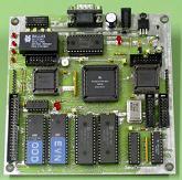
Why not post a good photo of this fellow, the Xilinx XC9572 in its break out board?
Thanks for the suggestions, guys. I’ll probably stick to parts with leads I can solder– I don’t know if I really want to get into doing reflow. I’m afraid I’d burn the house down or something. 🙂
For PCBs I’ll probably use Eagle, which I’ve done a little bit with before, or Proteus, which isn’t free but which I’ve heard good things about.
You can read about the XC9572 breakout board at http://www.awce.com/pbx84.htm . I have the manual for it too. It will probably be too small for this project, but it will give me a chance to get familiar with the programming software and hardware, which I think it the same regardless of whether you’re targeting a CPLD or FPGA.
Also on the question of parts availability, Mouser doesn’t sell any parts FPGAs from Altera or Xilinx at all. It does sell some less common brands. I did a quick Octopart search for “Xilinx Virtex-4”, which I believe is one of their higher-end FPGAs, and all the results were RFQs with prices of $300 each and up. Ouch!!!
digikey has both Altera and Xilinx parts. I would avoid the BGA package unless you have a pro to help you. The Cyclone III or Spartan-3a parts are probably the best choice for a self built board.
I’ve use the Xilinx XC95xx and XC95xxXL CPLDs in a number of projects and appreciate that some of them are available in PLCC packages that I can socket and then wire up without getting a PCB made. They work very nicely for implementing state machines and wide address decoders. They are okay for counters and adders, but since they have so many I/O pins compared to a PAL/GAL it’s easy to get overambitious (at least for me) with bit widths that don’t work out well (either too much propagation delay with dense logic, or more logic than would fit when optimizing for speed). They have fewer product terms per sum than traditional PAL/GAL devices, but can donate some unused terms to adjacent logic if needed so this limitation is usually not a problem.
I’ve also done a project with the Xilinx Spartan 3E and am in the planning stages with a Spartan 3 project. These are economically attractive from a standpoint of how much programmable logic you get for your dollar (far more affordable than the Virtex families), but are a real pain to prototype at home with. I’m using a version in a TQFP144 package, which has a 0.5 mm pitch on the leads; it used to intimidate me, but I’ve discovered that I can successfully hand solder this if I take my time (assuming of course that I’ve had a board made to put it on). The other irritation is that the cores run on 1.2 V and 2.5 V, with the I/O limited to 3.3 V. So if I need to mix with any older (5 V) technologies, I also need appropriate buffer chips to avoid frying the FPGA. If you can afford it (for me that means work is paying for it), a 4 layer board makes the routing easier and gives a nice solid power/ground plane, but 2 layer board is also doable (it just takes longer to route and I tend to obsess more about the power/ground trace width/lengths and go overboard on bypass caps).
If you are looking for a FPGA breakout board without a bunch of built-in I/O to get your way, SparkFun has a Xilinx Spartan 3E 500 board. I haven’t used this particular board, but I’ve been happy with all of the other breakouts I’ve gotten from them:
http://www.sparkfun.com/commerce/product_info.php?products_id=8458
Thanks, this is exactly the kind of rough scoping that I’ve found it difficult to do by just sifting through manufacturer’s web pages. I haven’t found anything that summarizes all the different manufacturers and families at a high level, so I know which ones I should even be looking at.
So yeah, it does look like the Spartan 3A or 3E could be a reasonable choice. I’d already reconciled myself with the necessity of doing a 3.3v design, but needing 1.25 and 2.5 volt supplies too is a little strange.
I think I’m going to limit my search to FPGAs with 3.3v or 5v I/O, solderable pins (no BGA), and no more than 144 pins. I just can’t imagine soldering some 400 pin monster, and anyway 144 pins seems about where the TQFP packages give way to the BGA ones. Some of the Spartan line fits this bill, and I haven’t looked at the Cyclone yet. Lattice and Actel also have some parts that could work, particularly the Lattice ECP. Has anyone ever used either of those? Am I better off sticking with the market leaders Xilinx and Altera?
Of course I don’t need to settle on a specific device or family now– I’m really just trying to get a ballpark estimate of what magnitude of logic I should expect, so I can scope the design appropriately.
OK, I think I’ve got enough info on FPGAs to move forward. Working with my constraint of 144 pins in a leaded package, it seems I’m looking at a device with around 5000 logic blocks (possibly as many as 15000), 100 available I/O pins, and costing between $10 and $30.
Lattice seems to have the most options that fit my needs, with the cheapest prices, and their XP2, ECP2, and ECP3 families look good. But they’re a small player in the market. That means I’m less likely to find Lattice help and examples from other hobbyists. Altera has some options in their Cyclone II family that could work too. Xilinx has two options in the Spartan-3E family, but that’s all. Unfortunately the newer Spartan-3A family is almost entirely in BGA packages, and the few that do come in a leaded packages have fewer logic blocks and I/Os than the Lattice and Altera offerings.
I’m bummed that there apparently aren’t more Xilinx options that fit my needs, since there seem to be far more tutorials, books, and such aimed at Xilinx FPGA development than other brands.
One other option would be to buy the Spartan 3E 500 breakout board from SparkFun, and incorporate it directly into my final hardware as a daughtercard that mates with four sockets on the main board. I’m not sure if that would cause noticeable signal degradation, as compared with putting the whole design on a single board.
I tried to find a 5V FPGA once – the ones that still exist are very difficult to get. The majority of FPGA’s these days all have multiple voltage rails and limit I/O to 3.3V. MachXO (Lattice) is one that you can run on one voltage source, but it looks like it’s classified as a big CPLD and not a FPGA.
Isn’t it sad that a breakout board from Sparkfun (http://www.sparkfun.com/commerce/product_info.php?products_id=8458) costs $99, but a whole development kit from Xilinx (http://www.nuhorizons.com/xilinx/boards/spartan-3/SP3eStarterKit/index.asp) is only $149? And it comes with Ethernet and LCD and … and … !!!
What also need to keep in mind, is that most FPGAs (except for most of Actel’s) does not contain the design when powered off, you need to add a small EEPROM to the design from which the FPGA loads during power up (no worries when programming it, the EEPROM is put in the JTAG chain to be flashed it with your code). CPLDs, like the Actel FPGA’s do not use EEPROMs either.
Yes the starter kit is certainly the way to go for experimentation, but for a finished product, you’ll probably want a breakout board, or just the bare FPGA.
I’m familiar with the theory of using an EEPROM to program the FPGA at power up, but very fuzzy on how this works in practice. What kind of programmer do I need to program the EEPROM itself? How does the EEPROM need to be connected to the FPGA? I’m sure the answers are all documented, but it’s something of a mystery to me now.
Is there such a thing as a generic JTAG programmer, for EEPROMs and stuff? I have an AVR ISP mkII, is that a JTAG programmer, or something AVR-specific?