

3D Breakdown
OK, enough discussion of FPGA gate counts for the time being. It’s time to talk about how this 3D Graphics Thingy might work, at a functional level. My current thinking is to divide the system into four major pieces:
CPU – Determines what objects are visible to the camera
Vertex Processor – Transforms and lights object vertices
Pixel Processor – Fills the interiors of polygons
Video Buffer – Stores and displays an image on the screen
The only pieces that are strictly necessary for 3D graphics are the CPU and video buffer, since the CPU could do all the necessary computations in software, but the result would be incredibly slow. Implementing vertex and pixel processing in dedicated hardware will dramatically increase the number of polygons per second that can be drawn. This entire project boils down to just a performance optimization then, albeit a complex one. Adding vertex and pixel processors will improve performance through parallelization across multiple hardware units, and pipelining within a unit.
Video Buffer
The core of the video buffer is just some dedicated memory for storing a screen image, and hardware to scan that memory and generate a VGA-compatible video signal. I’ve already implemented a video buffer previously for BMOW, so this is familiar territory. However, the 3DGT video buffer will differ from BMOW’s in several respects.

Bit depth – Images will be stored in video memory in a direct color format, with somewhere between 16 and 32 bits per pixel. Each pixel’s data will be directly interpreted as 5:5:5 or 8:8:8 RGB data, and sent to a high-speed RAMDAC to create the three analog color voltages for the VGA signal. This will require larger, faster video memory than BMOW, which has 8 bits per pixel used as an index into a secondary color palette, which determines the final RGB color.
Contents – In addition to the framebuffer for the currently displayed image, the video buffer memory will also contain other types of video-related data. Depending on the final design, this may include a backbuffer to support double-buffering, a depth buffer to support hidden surface removal, and texture image data.
Access – Getting data in and out of the video buffer quickly will be essential for good performance. Several 8-bit RAMs will probably be used in parallel, to permit reading and writing of 32 bits or more at a time. A solution for providing simultaneous access to both the CPU and display circuitry is also essential. This is noticeably lacking with BMOW, causing visible “noise” on the screen during CPU access to the video buffer. I have a few ideas on how to accomplish this, with various pros and cons, which I’ll describe in a later posting about the video buffer details.
The video buffer is a critical component of the 3DGT system, and also the one I’ll need to implement first. However, it’s also the one I find least interesting. Other than the question of avoiding CPU/display memory contention, the rest of the video buffer functionality is relatively straightforward and boring. I won’t feel guilty about reusing purpose-made parts or VHDL libraries for this piece, so I can move on more quickly to the more interesting bits.
Pixel Processor
This is where most of the real interesting action will occur. It’s the pixel processor that will primarily determine what kind of graphics features 3DGT supports, and what sort of performance it has. Most of my design work will be here, and the FPGA will probably be filled by units of the Pixel Processor more than anything else.
So what does a pixel processor do? It’s supplied with the X,Y,Z coordinates of three vertices for a triangle. It may also be supplied with color, texture, and other data about each vertex.
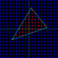
First, the pixel processor must determine which screen pixels are inside the triangle. This involves some math that’s somewhat complicated to describe, and much more complicated to imagine implementing efficiently in hardware. There are also some interesting boundary cases, like to how to handle pixels that are mathematically exactly on a triangle edge. Count them in, and they’ll also be drawn by an adjacent triangle that shares that edge, causing a double-draw. Count them out, and the pixel won’t be drawn by the adjacent triangle either, creating a gap.
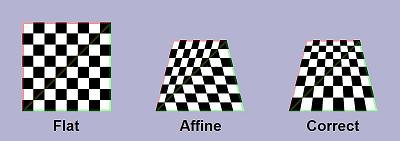
For every pixel that’s inside the triangle, the pixel processor must interpolate the values from the vertices to determine intermediate values at that pixel. For example, if the top-left vertex is supposed to be white, and the top-right vertex is supposed to be black, then a pixel about 75% of the way along the top edge should be dark gray. Interpolation is further complicated by the fact that 2D screen space interpolation (such as my dark-gray example) isn’t actually mathematically correct. If that top-right vertex had a much greater Z value than the top-left one, implying the 2D projection of a 3D edge that disappears away and to the right, then 75% gray would look subtly wrong. To be accurate, perspective-correct interpolation must be formed, but this is more challenging and expensive to implement in hardware. Early 3D hardware such as the Playstation did screen-space interpolation, but all modern 3D hardware does perspective correct interpolation.
Once the interpolated values are determined, each interior pixel must be drawn into the video buffer memory. This involves several considerations:
Z-depth – Has something else already be drawn which covers this pixel and is closer to the camera? If so, it should obscure this triangle, and further processing of this pixel for this triangle can be aborted.
Texture Lookup – Most triangles will be textured, instead of just being solid colors. This means a portion of a 2-dimensional texture image stored elsewhere in the video buffer must be “glued” onto the triangle. The correct pixel from the texture must be fetched, and combined with the interpolated color value for this pixel.
Texture Blending – When applying textures to a triangle, the resulting image may be larger or smaller than the original texture, depending on the size of the triangle to which it’s applied. This effectively results in scaling the texture image. The scaling can be done using point sampling, which requires looking up a single texture pixel for each screen pixel, or with various types of filtering, which require looking up many texture pixels and combing the result.

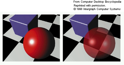
Alpha Blending – The vertex color, texture color, or both may include an alpha component along with the RGB components. If supported by the hardware, alpha blending allows for the specification of translucent colors, and the alpha value determines the degree of opacity of the color. Implementing alpha blending in hardware requires reading the color value that was already in the video buffer at this pixel, computing a weighted average with the new color value, and writing the result back. As a result of this extra step, alpha-blended polygons are more expensive to draw than opaque ones. The left frame below shows a red sphere composed of opaque polygons, while the right frame shows a translucent sphere rendered with polygons using alpha blending.
Fogging – In the real world, objects in the far distance appear hazy and with desaturated colors due to atmospheric effects. This is an important visual cue to indicate that an object is far away, and synthetic 3D scenes containing distant objects in eye-popping bright colors look unnatural. Hardware can provide this effect, called fog, by computing a weighted average of the polygon color with a global fog color (typically grayish-blue), according to the Z-depth of each pixel. Fog can be computed as a linear function of Z, or using more complex functions for better-looking results.
Custom Pixel Shaders – The ultimate in flexibility is to provide a custom pixel “shader”, which is just a small program that’s run by the pixel processor to compute the result for each pixel. All modern graphics hardware uses pixel shaders, which permit any crazy set of rules you can imagine to determine the final color. Older fixed-function graphics hardware allowed various built-in features like alpha blending and fogging to be turned on and off, but could not perform any custom pixel operations not explicitly built-in.
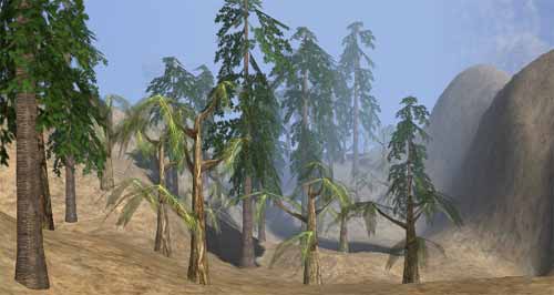
3DGT will likely be a fixed-function graphics system, in order to keep the project complexity down. I hope that it will support all the other features of z-sorting, alpha blending, texture mapping, and fogging, but it will depend on how complex those tasks prove to be. If they all prove too daunting, a credible but basic 3D system could still be constructed without any of them, using the CPU to sort polygons by depth, and rendering solid colored triangles. If the polygon count is high enough, and per-vertex lighting is performed, the result could even look quite good. Here’s an example:
I’ve described the pixel processor as if it were a sequential state machine, evaluating one pixel of one triangle at a time. This will almost certainly not be the case, as substantial speedups can be gained here with the right hardware design.
The computation of each pixel can be pipelined, so for example the alpha blending of one pixel might proceed concurrently with the z-test of the next pixel. The texture processor will likely have a large number of pipeline stages, since subdivision of a repeated task into n stages of equal duration yields an improvement of n in overall throughput.
Pixel computation can also be parallelized, by creating many pixel processing subunits, and assigning each to a different region of the screen. Because the color of each pixel is unaffected by its neighbors, the subunits could operate completely independently. However, additional hardware would be required to farm triangles out to the correct subunits, and to avoid contention between the subunits for the same RAM chips.
Vertex Processor
Like the pixel processor, the vertex processor also receives data about the vertices of triangles. In the case of the vertex processor, this data is supplied by the CPU. Vertex positions for an object are specified in object space, which is the fixed 3D coordinate system in which that object was modeled. The vertex processor is also supplied with information about the object’s position and orientation in the world, as well as the camera’s position and orientation, and parameters like the camera zoom factor. From this, a projection matrix can be constructed to transform vertices from world space to camera space, and from camera space to screen space.
Thus the primary job of the vertex processor is to do lots of multiplications of vectors with matrices. And since that task can be broken down into multiplication of vectors by columns of the matrix, all the hardware really needs is to multiply vectors by vectors, computing the dot product. Multiply and accumulate is the name of this game, since the dot product of two vectors [ x0, y0, z0 ] and [ x1, y1, z1 ] is just x0*x1 + y0*y1 + z0*z1.
By the way, the singular form of vertices is vertex. The singular of matrices is matrix. Every time I hear someone construct a new singular word “verticee” or “matricee” by incorrect derivation from the plural, I have to resist the urge to laugh. Unfortunately, this seems to be a common mistake, at least when speaking, if not when writing.
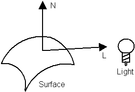
In addition to projecting vertex positions into screen space, the vector processor is also responsible for lighting each vertex. In this context, lighting means determining what color should be assigned to the vertex, passed to the pixel processor, and then interpolated across the face of the polygon. There are a tremendous number of different ways to compute lighting, but the simplest is to compute max(0, n dot l), where n is a unit normal vector pointing away from the polygon’s face in the “outside” direction, and l is a unit normal vector from the vertex in the direction of the light source. Where the light is shining directly down on the surface, n and l are coincident, so n dot l = 1 and the vertex is maximally lit. When the light is shining tangentially to the surface, and n and l are perpendicular, so n dot l = 0 and the vertex is not lit. When the light is shining from behind the surface, n and l point in opposing directions, so n dot l is less than 0, and max(0, n dot l) evaluates to 0, and once again the vertex is not lit.
The vertex processor can also implement an optimization known as back face culling. For a solid 3D object, every triangle on its surface has a front and a back face. A moment’s thought shows that the back faces can never be seen, because they will always be obscured by the front face of another triangle on the other side of the object. The vertex processor can detect back faces easily, since the normal vector for a back face always points away from the camera position. Back faces can be rejected by the vertex processor, and don’t need to be sent to the pixel processor at all. However, this optimization only works for solid 3D objects. A 2D object in a 3D space, like a leaf, must have both faces visible.
Another important job of the vertex processor is clipping. Imagine that after projection into screen space, two of the three vertices lie within the boundaries of the screen, and one lies outside. The pixel processor is typically not equipped to deal with this- it assumes all vertex positions are within the boundaries of the screen, and may “wrap around” and begin filling pixels at the opposite side of the screen while trying to fill a triangle that extends beyond the screen’s edge. To rectify this, the vertex processor must clip the triangle, inserting new vertices and creating two or more new triangles that lie completely within the screen’s boundaries. Colors, normals, and other properties must then be determined for these new vertices by interpolating the values for the original vertices. I fear this is going to be very difficult for me to implement in hardware, but I don’t see any way around it.
Like the pixel processor, the vertex processor can also use custom vertex shaders, or be a fixed-function design. Vertex shaders could be used to generate more advanced effects, like procedurally deforming the vertices in an object, or creating triangles from 3D surfaces such as Bezier patches and NURBS.
CPU
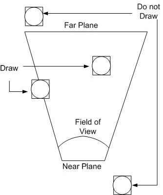
The job of the CPU is to determine the set of objects that must be drawn, and their positions and orientations. As objects move and rotate through the simulated 3D world, the CPU maintains their state. For every frame of video, the CPU considers the state of each object, and the camera’s position and orientation, and determines which objects are potentially visible. This process is known as culling. For example, if an object is behind the camera or off to the side, it can’t possibly be visible, and it’s triangles don’t need to be passed to the vertex processor. Objects that are beyond a maximum distance called the far plane are also culled, so that the camera’s visibility doesn’t extend to infinity.
Putting It All Together
There’s a lot to digest here, and even writing a software simulation of the whole pipeline using C++ would be a substantial task. Implementing it in hardware will definitely require me to learn many techniques I don’t yet know, and at the moment, many of these functions don’t lend themselves to any hardware implementation I can imagine. As I reread what I’ve written, I’m wondering if I haven’t bitten off a larger project than I originally realized. This functional breakdown doesn’t even touch upon questions like the floating point representation used for all these numbers, and how to implement various mathematical operations in hardware. Yet the very existence of 3D graphics hardware going back several decades proves that it can be done. No doubt it’s going to be a challenge, but I’m excited to take it on.
Read 4 comments and join the conversation4 Comments so far
Leave a reply. For customer support issues, please use the Customer Support link instead of writing comments.
With all the matrix multiplication (and the multiplication in any interpolation), you should probably consider using FPGAs that include dedicated multiplier units. These are much faster and more compact than multipliers built with the general-purpose purpose logic.
These can also be useful for division (or at least computing the reciprocal of z) by using a look-up table for an initial estimate followed by a few iterations of Newton-Raphson’s method (which requires a few (2?) multiplications on each iteration) to refine the result. 32 bits of accuracy is attainable in only 4-5 iterations, which certainly beats out basic binary long division’s 1 bit/cycle.
On the other hand, much of this would go into the vector processor and there’s no point in optimizing its multiplication and division if it’s going to spend most of the time waiting on the pixel processor to fill in the triangle’s pixels. Need to figure out the relative speed of these processors.
Thanks, good suggestion. All the FPGAs in the range I’ve looked at do include hardware multipliers, somewhere between 3 and 20. That seems kinds of low, now that I think about it.
That’s also a great point about balancing the performance of the different stages. If the pixel processor is significantly slower than everything else, then the vertex processor can be implemented in software on the CPU with no loss of speed. No point in making a “fast” vertex processor in hardware that spends most of its time waiting for the pixel processor to be ready. Ideally the two should be roughly balanced. This will require some serious parallelization inside the pixel processor in order to make it fast enough.
Actually, doing the vertex processor in software might not even be that slow, since many CPUs have vector multiply-and-accumulate instructions built-in. That’s basically what the SSE instructions on the x86 are. I think MIPS, ARM, etc may have something similar.
Hi,
I have started to do a project similar to yours (GPU-like) in VHDL.
I have done a few parts already working on simulator…
I have quite some experience in software rendering (I even worked on an OpenGLES soft implementation for mobile) and also in tricks done by HW GPU manufacturer (especially small embedded stuff)
If you are still motivated, please send me a mail.
Cheers,
Romain.
hi… i am doing a project on image processing using fpga.. in that i want to store image and process it using fpga and display the processed image on lcd screen..
for programming fpga i am using xilinx system generator s/w…
this is just my aim about how my project should work,…
can u help me on how can i do this,,,….