

FillRect
OK, time to get back to 3D Graphics Thingy! 3D graphics rendering, implemented in hardware. Here we go. Starting right now. Any time now. 1, 2, 3, go. Getting ready, this is it, here we go. OK, really, going to start now.
I stared at a blank sheet of paper for a long while yesterday, and realized I have no idea what I’m doing. How do you make a digital circuit that draws stuff? Where do you even start?
Assuming I had some video memory, and a circuit to display the contents of video memory, I might implement a FillRect function in C like this:
void FillRect(int left, int top, int right, int bottom, int color) {
    for (int y=top; y<=bottom; y++) {
        for (int x=left; x<=right; x++) {
            memory[x][y] = color;
        }
    }
}
Taking this a little further, I could assume a screen width and height of 256 pixels, and one byte per pixel, for a total video memory size of 64K. That would enable me to directly use the X and Y coordinates of a pixel to determine its memory address, by using Y as the upper 8 bits of address, and X as the lower 8 bits. The revised C code would be:
void FillRect(uchar left, uchar top, uchar right, uchar bottom, uchar color) {
    for (uchar y=top; y<=bottom; y++) {
        for (uchar x=left; x<=right; x++) {
            memory[(y<<8)|x] = color;
        }
    }
}
Now how do you build hardware to do that? After more staring at a blank sheet of paper for a while, I started drawing things, and eventually came up with this:
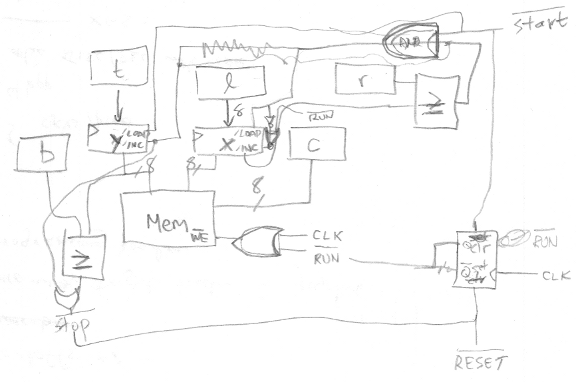
My scrawl is difficult to follow, so I cleaned it up in a drawing program. In the diagram below, the data path is drawn in blue, and the control path in orange. All the control signals are assumed to use positive logic for clarity (1 = active), although in a real circuit with real chips, most would actually use negative logic. The five blue boxes along the top are all 8-bit registers, something like a 74HC377. The two darker blue boxes for X and Y are 8-bit counters, like a 74HC393 maybe. For the counters, I assume that their load input takes priority over their count input, if both are asserted simultaneously. The two boxes labeled “=” are comparators that output true when their inputs are equal, like a 74HC688. The orange run box is a single flip-flop with synchronous set and reset inputs.
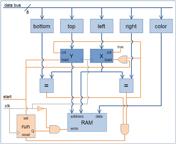
How does this work? Initially run is false, so the output of the AND gate connected to the RAM’s write input is also always false, and nothing gets written. To start things going, the CPU (not shown) writes the desired values to the bottom, top, left, right, and color registers for the rectangle to be filled, and then asserts start. At the next clock edge, three things happen:
- run is set to true
- Y is loaded from top
- X is loaded from left
Notice the clock signal itself is used as a control signal, connected through an inverter to the AND gate feeding the RAM’s write input. On the next clock cycle following start, during the second half when the clock signal is low, the output of the AND gate becomes true, and the value in the color register is written to the address specified by the X and Y registers. Oh my God, a pixel was just filled!
The X register’s count input is connected directly to true. At the next clock edge, X is incremented by one, and on the next clock cycle, the neighboring pixel one spot to the right is filled. This continues until X reaches the value stored in the right register, at which point the output of the comparator becomes true. This forces X to be reloaded with the value from left (load preempts count), and also increments Y by one, accomplishing a movement to the start of the next line.
Eventually the filling operation reaches the last pixel of the last line, when Y equals bottom and X equals right, and the output of both comparators becomes true. This resets the flip-flop, forcing run to false, and disabling any further writes to video memory. The FillRect operation is complete.
With work, this FillRect hardware could be generalized to FillTriangle hardware more similar to what 3DGT will need. If left and right were initially equal, and then incremented or decremented by a fixed step on each new line, then flat-bottomed triangles of any shape could be drawn. The per-line steps for left and right would be the inverse slopes of the triangle edges. To draw any general triangle without the flat-bottom limitation, the same circuit could be used again in reverse to draw a flat-top triangle connected to the first flat-bottom one. Alternatively, the hardware could be extended to draw the complete triangle directly, by adding a new knee register, and changing one of the line slopes when Y reaches knee.
Read 3 comments and join the conversation3 Comments so far
Leave a reply. For customer support issues, please use the Customer Support link instead of writing comments.
Wow. Impressive! I would have never thought of writing some code to give myself the material to draw up the circuit! Good luck with this beast. 😉
I had another idea to simplify this a little. Instead of top, left, bottom, and right, the circuit could use top, left, width, and height. Width and height could be implemented using down counters, triggering a jump to the next line when width equals zero, and the end of drawing when width and height both equal zero. This would eliminate the need for the comparators in the circuit.
Also, the top register isn’t really needed. The CPU could directly load Y from the data bus at the start of a new FillRect operation. The top register is never used after filling begins, so it’s just a waste.
Great project, thanks for sharing!
Brad