

Shrinking the Backcountry Logger
 Shrinking a design as far as possible can be an addictive hobby. Even though PCBs for the first backcountry logger design aren’t yet back from the board house, I’ve been busy working on a revised version that’s just 1.9 x 1.1 inches (49 x 28 mm). That’s about the size of 3 AAA batteries laid side-by-side. It’s small!
If you’re just tuning in, the backcountry logger concept is a portable ATmega-powered device that collects temperature, air pressure, and altitude data, and shows graphs on a built-in LCD screen. It’s intended for hikers, climbers, and other outdoorsy folks who want to know if it was colder last night than three nights ago, whether the ridge they’re on is the 10200′ or 10600′ one from the map, or whether a storm is likely soon. Much attention has been giving to minimizing power consumption, so the battery should last many months.
 Here’s the original logger design. It’s 2.75 x 1.8 inches, and uses all through-hole parts. The LCD is a Nokia 5110 on a breakout board, mounted onto the main board with an 8-pin 0.1 inch header, and covering the upper two-thirds of the main board. Similarly, the Bosch BMP085 temperature and pressure sensor is on a second breakout, mounted with a 6-pin 0.1 inch header and covering the lower-left corner of the main board. The battery is a CR2032 coin cell, and projected battery life is 8-12 months.
While the new design is functionally similar to the original, it replaces virtually every component with a smaller SMD version. It also drops the breakout boards, soldering the components directly to the main board instead. The LCD is replaced by a 128 x 64 OLED, which is physically smaller but has a higher resolution. To meet the higher power demands of the OLED, the coin cell is replaced by a single AAA cell and a 3.3V boost regulator. The addition of an external EEPROM provides space for higher resolution or longer-term data storage than is possible with the ATmega’s built-in EEPROM. And as a last-minute addition, the new design also adds a SignalQuest SQ-SEN-200 omnidirectional tilt and vibration sensor, which I hope to use to measure periods of movement to compile trip duration stats. Projected battery life is about 5 months.
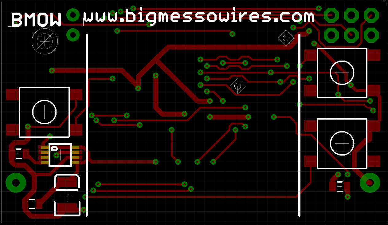 The majority of the top layer is covered by the OLED itself, leaving precious little space for component placement. It’s just the three tactile switches, boost regulator IC, and a couple of capacitors. The tactile switches are the thinnest I could find (2.6 mm), so as not to add too much to the overall thickness of the logger. I would have dearly loved to use the user-friendly switches with the 12mm base, but there simply wasn’t enough room. Instead, the switches here are the 6mm base type with a 3mm round button. A single drill hole in the top-left corner provides an option to wear the logger on a lanyard or keychain.
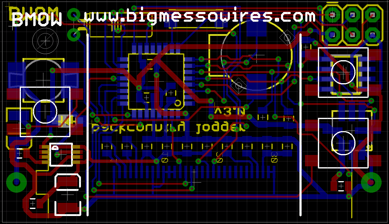
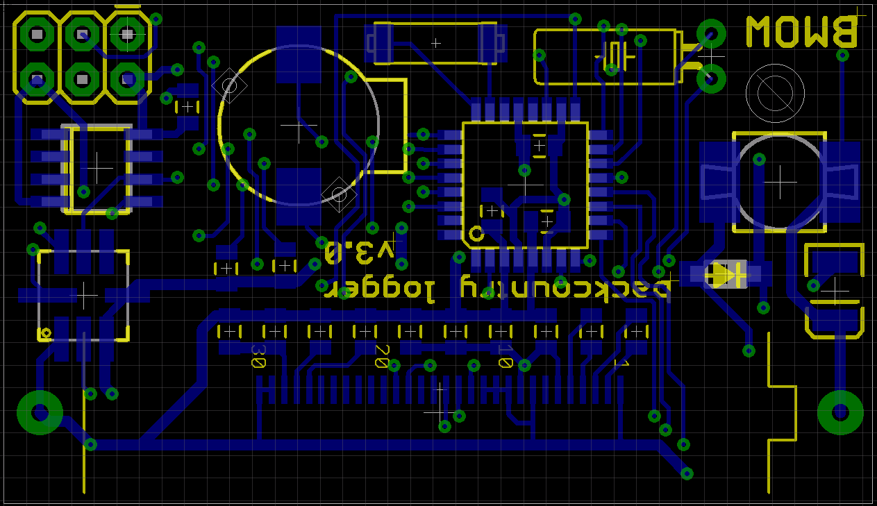 The bottom layer is were most of the action is. The ribbon connector from the OLED wraps around the bottom of the board, and its 30 pins are soldered at bottom-center. The AAA battery spans the bottom third of the board, lying on top of the ribbon connector. Down the left side are the ISP header, external EEPROM, and BMP085 sensor. The right side is occupied by an inductor, diode, and capacitor required by the boost regulator. Squeezed into the center is the ATmega 328 in TQFP package, a tiny speaker, 32 kHz crystal, and the SQ-SEN-200 vibration sensor. The SQ-SEN-200 is the barrel-shaped component at top center, and its internal switch chatters open and closed whenever it’s bumped or moved.
Cramming all these components into the space available was an interesting challenge. The resulting board is almost as small as theoretically possible, since the width is already constrained by the size of the battery, and the height could only be a few mm less before it would be shorter than the OLED screen. I plan to wait a while before sending this board for manufacturing, at least until I’ve received the boards for the original design and confirmed that everything works. All this waiting for boards is maddening!
Read 7 comments and join the conversation7 Comments so far
Leave a reply. For customer support issues, please use the Customer Support link instead of writing comments.
It looks like you have sandwiched some bypass capacitors between the Atmel microcontroller and the PCB. While you could make this work with thin enough caps under a DIP package, this seems infeasible with a TQFP. You could move them to the other side of the PCB, even though this would necessitate raising the display a little off the PCB. If you were using double-sided sticky tape to attach the display, you could use caps that are thinner to make it work.
Ack, you’re right! That was totally unintentional. What was I thinking?
What boost regulator did you choose and how did you choose it? While I’ve used some switching regulator circuits before, efficiency hasn’t been a critical issue, so I’ve mainly selected based on cost, availability, and ease of hand soldering. But I may soon start a small project with wireless data entry devices (score keeping for the local curling club) and the single cell AA seems like a convenient power source.
It’s a MAX1675 regulator. There are a huge number of boost regulators out there, so I wasn’t sure where to start. I narrowed the field to a few families that seemed to be most popular, then selected this one for its low-ish external part count and ability to work with input voltages as low at 0.7 volts.
According to the datasheet, at Vin = 1.2V, Vout = 3.3V, Iout = 10 mA, efficiency should be about 90%.
Hey! that is great I am looking for something like this in order to use Altium, I have used Eagle for several years and I want to move to Alitum, would you let me do the PCB? If you have time… or if you are not interested could you share your schematic?
and take a look to these enclosures
http://www.okwenclosures.com/products/okw/minitec.htm
Those are some nice-looking enclosures… thanks for the link! The shrunken PCB is already done and sent for manufacturing. There’s a small chance this may develop into a commercial product, so I’m keeping the design files private for the moment, sorry! If you want some design files to use for layout experiments, check out my Tiny CPU project.
OK thank you! I hope to hear some good news about this product, good luck!