

I am the Best Solderer in the World
Who’s the best solderer in the world? I am. That’s right. All you other soldering fools just want to taste my sweet victory because the Logger Mini works!
OK, in reality I may be in the bottom decile of the soldering class, but after assembling this bad boy, I’ll never fear soldering anything again. All surface mount parts, all crammed in way too densely, all impossible to debug when it doesn’t work… but it does work. Me and my big, bad soldering iron have tamed this beast. Most of the assembly wasn’t too bad, and I was able to get the majority of the parts soldered within a couple of hours. The fine-pitch ICs didn’t give me too much difficulty this time either. But as always, there were a few twists and turns along the way.
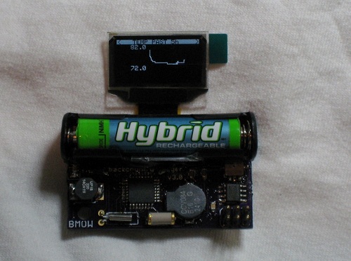
As I predicted in my last post, there were clearance problems between the battery holder and several components. I unwisely designed the battery to sit on top of a few smaller components, and it quickly became clear that wasn’t going to work. I cut away part of the holder’s body with a knife to make things fit, but the real solution will require a different style of holder or a slighly larger board. I also struggled with a missing component when I discovered I’d ordered a 390 Ohm SMD resistor instead of 390K Ohm. Rather than string 1000 resistors together in series, I cut up a 390K resistor pack I had on hand, bent the pins to size, and shoehorned it onto the SMD pads.
The BMP085 pressure/temperature sensor also gave me a nasty surprise. Its connection points are underneath the device, but for some reason I thought they also extended outward to the edges of the device and up the sides, providing access for the soldering iron. Nope. All the connection points are completely hidden underneath, inaccessible. Fortunately the pads on the PCB extend out about 1mm beyond the perimiter of the chip. What I ended up doing was tinning all 8 pads, then placing the BMP085 on its footprint, and reheating each of the tinned pads in turn while I pushed down on the chip from above. The idea was that the solder would transfer heat under the chip, melting the solder underneath and bonding it to the connection point sitting on top of it. It seemed to work.
The real challenge proved to be debugging. After finishing assembly, the screen remained stubbornly blank. With no idea if it was a software bug, circuit design error, soldering mistake, or defective part, and no good way to troubleshoot, I was pessimistic I’d ever fix it. This is the kind of situation where I can easily convince myself it’s hopeless and give up, but I tried to be methodical at exploring problem theories as much as possible. Eventually I tried touching an oscilloscope probe to each of the 30 pins on the display connector ribbon, to try to see what was going on, and I discovered that touching one particular pin caused the display to start working! After retouching that pin with the soldering iron, I was in business.
The Logger Mini worked fine for many hours, and I started work on the necessary software changes. Eventually, though, the BMP085 sensor stopped working. The sensor actually lies partly underneath the battery holder, making the problem especially difficult to troubleshoot. Again, I desparied of ever finding a resolution. After many false starts and much hair pulling, I desoldered the battery holder, which was less difficult than I’d feared. I powered the board with a pair of alligotor clips while I poked at the sensor. After retouching all the sensor’s pins with the iron, it sprang back to life. I then replaced the battery holder, restoring everything to factory new condition.
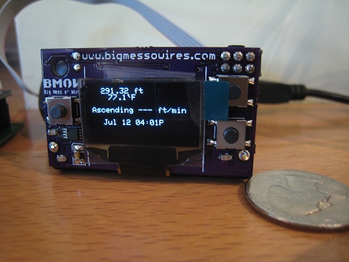
I made a few quick power measurements of the Mini, testing current draw straight from the battery. With the display on, the current is between about 8 to 15 mA, depending on how many pixels are illuminated. With the display off and the logger asleep, the current is 120 uA. That’s a higher sleep current than I was expecting, and some more investigation is needed to determine why. Still, with those current numbers I estimate the battery life will be a very respectable 4-5 months.
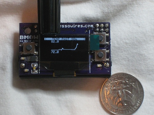
The photos here show a straight port of the software from the Logger Classic, and the graphs still only use the 84 x 48 resolution of the Classic. I need to do some more work to fit everything to the Mini’s 128 x 64 display, but development time is running out before the first of my Sierra hiking trips.
Read 4 comments and join the conversation4 Comments so far
Leave a reply. For customer support issues, please use the Customer Support link instead of writing comments.
Quick question, which OLED display are you using? (didn’t see which model in the post)
It’s the SSD1306 UG-2864HMBEG01. Pretty easy to use, once you get the connector soldered properly! http://cgi.ebay.com/128X64-OLED-LED-Display-Module-UG-2864HMBEG01-SSD1306-/130495997889?pt=LH_DefaultDomain_0&hash=item1e622ae7c1
Congratulations on getting it going! It’s looks excellent and that dinky little display looks super.
You must have used a magnifier glass at the very least, can’t imagine to put all together bare eyes and no mistakes :), Well done.