

New Floppy Emu Boards and Supply Noise
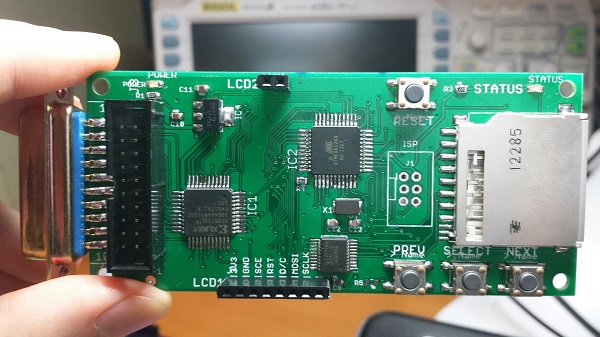
I finally got the new Floppy Emu revision 1.1 boards! Rev 1.1 has a few minor tweaks to prepare for selling assembled hardware. I built four of them with a soldering mini-marathon, and three of them work. The fourth I think I toasted somehow, but I’ll check it in more detail later. 75% yield isn’t so good. 🙂
Unfortunately something isn’t quite right. With the new boards I’ve built so far, I’m seeing anywhere from 3X to 10X more noise on the 5V and 3.3V supply lines, and I think this is causing random resets and spurious interrupts and other phantom problems. The noise is very regular, with a frequency of between 80 kHz and 130 kHz on both supplies. I was able to bring the supply noise under control by soldering an extra 10uF capacitor between the 3.3V and GND pins on the LCD, but it shouldn’t need one, since there’s already a 10uF cap between 3.3V and GND on the main board. Yet the difference with and without the extra cap is like night and day:
Rev 1.1:
new LCD (with extra 10 uF cap) and SD card: 80 mV noise on 5V supply, 100 mV on 3.3V supply
new LCD and no SD: 60 mV on 5V, 50 mV 3.3V
old LCD and SD card #1: 380 mv on 5V, 100 mV on 3.3V
old LCD and SD card #2: 840 mv on 5V, 280 mV on 3.3V
old LCD and no SD: 900 mv on 5V, 340 mV on 3.3V
Rev 1.0:
new LCD and SD card: 100 mV on 5V, 120 mV 3.3V
new LCD and no SD: 80 mV on 5V, 120 mV 3.3V,
old LCD and SD card: 100 mV on 5V, 120 mV 3.3V
old LCD and no SD: 80 mV on 5V, 100 mV 3.3V
I guess I could just go with the extra capacitor on all new boards, and call it done, but I’d really like to understand what’s going on. Quite a few things changed between revisions, any of which could affect supply noise:
- New board design relocated some parts and re-routed some traces
- Boards were manufactured by a different fab
- Using an ATMEGA1284 instead of ATMEGA1284P
- Different brand of 3.3V regulator
I’m tempted to blame the 3.3V regulator, but I don’t quite see how it could be at fault. The old regulator from rev1.0 and the new regulator from rev1.1 are virtually identical.
I’m going to do some more experiments before deciding how to proceed. If you’ve got any ideas on what to check, please leave a note in the comments!
Read 12 comments and join the conversation
12 Comments so far
Leave a reply. For customer support issues, please use the Customer Support link instead of writing comments.
My first thought is that the regulator is oscillating. It looks like you are using ceramic capacitors on the output of your Vreg. The ST part number does not talk much about stability and capacitance, so it might very well have been perfectly ok with 10uF of ceramic capacitance, but per my reading of the On Semi part, it requires either a good chunk of ceramic capacitance or some ESR in the capacitor. (See Figure 12 on Page 6). That also would be why the two in parallel “fixed” it. The fix is to use probably close to 30uF of capacitance, use a capacitor with at least 100mΩ of ESR (anything besides a ceramic), or use a Vreg that is unconditionally stable with ceramics (my preferred solution, but not available as an easy mod to an existing pcb).
Also, you probably got lucky with the ST part, since it doesn’t talk about stability conditions, it may be just on the edge of working with your part.
“Virtually” identical. Always a warning sign.
Sounds possible. On the scope, the 3.3V supply shows a very regular sawtooth or triangle wave pattern – not anything sinusoidal or random. The 5V supply shows a more complex repeating pattern, but it’s one I could believe is caused by changing load from the 3.3V regulator.
Yes, I’m using ceramic capacitors: 0.1uF at the regulator input, and 10uF at the output. This is what the ST datasheet shows for their example circuit (figure 4). The “extra” capacitor I added to the LCD is electrolytic.
The On Semi datasheet shows 10uF at both input and output. I actually tried adding more capacitance at the input (across the 5V supply), and it definitely helped, but didn’t eliminate the noise. The On Semi datasheet also says the output capacitor can be any composition, as long as it is a minimum capacitance value of 4.7 uF with an ESR from 33 mOhm to 2.2 Ohm.
So a high ESR is a *good* thing here? I always viewed it as something undesirable.
So you’d recommend I replace the 10uF ceramic output cap with a 10uF tantalum, or a 30uF+ ceramic, or add additional (electrolytic) capacitors where possible as a post-fix?
I think you are right about the 3.3V as the cause on the 5V line. Pretty much everything you mention above makes sense for my understanding of what would be causing this.
It shouldn’t hurt (ignoring the case of other sensitive regulators) to have extra capacitance on the 5V input line. The ON Semi datasheet recommends 10uF of ceramic and even if something doesn’t spec an input cap, unless I have one really close already, I usually have >1uF on all regulator inputs.
Ceramic caps have a very low ESR; I do not know the typical values, but if something talks about a required ESR > ~10mΩ, you probably should be careful about them.
ESR is only a good thing in that it moves the frequency response poles and zeros of the system around in ways I have not had to calculate yet, and have not learned in school yet either. There tends to be a band, like the 33mΩ to 2.2Ω for this part.
The goal is to either put something right into the band that for a capacitor value the ESR is right, or push the capacitance to the point the ESR is unimportant. The plot I mentioned is great to look for in any vreg datasheet. Any of the three resolutions should make a difference. Try them and see which does the best job.
PS; Be aware that ceramics also have a voltage coefficient, such that the effective capacitance drops as the bias increases. if you changed out the 10uF cap, that also might be a contribution ( i.e. it might be hanging out closer to that 4.7uF number as well).
Hope this helps more than confuses.
I’ve confirmed that an extra 33uF electrolytic capacitor added directly across the 3.3V regulator pins eliminates the regulation noise on the boards I already built. Great! Now I’m trying to decide what solution to use on the remaining boards I’ve yet to build – hopefully something that works with the existing PCB footprint for a 0805 SMD capacitor. I checked DigiKey, and 10uF+ tantalum caps in 0805 size seem to have ESRs of 6-8 Ohms, which is too high. There are some with ESR as low as 1.1 Ohms, but I worry that’s getting too close to the On Semi regulator’s limit of 2.2 Ohm, and those caps are about $1 each! On the other hand, a 47uF 0805 ceramic cap is about $0.75 each, which still seems like a lot for a single capacitor. These don’t even advertise any ESR value, but the capacitance is high enough that it should work. As far as I can tell, there are no aluminum/electrolytic (these are the same) caps that come in a 0805 SMD package.
Yeah and those 47uF caps will have about 15-20uF effective capacitance at 3.3V. (I pulled up a datasheet for the JMK212BBJ476MG-T http://www.yuden.co.jp/ut/product/category/capacitor/putpdf/JMK212BBJ476MG-T.pdf, look at the middle of page two) That might be ok for your regulator.
The 6TPU10MSI tantalums might be a reasonable choice for the output cap, but you’re right, this is getting into expensive part category. Or the 6TPU22MSI which are 22uF.
Other options:
Swap out some of your 100nF caps in 0805 on that rail with the 10uF ones you are using now. It will compromise your decoupling some, but it might go more good than harm.
Replace the voltage regulator with the ST part. It worked previously, it might work again.
It appears you have plenty of room for trick soldering of more caps in parallel with the output one and directly on the leads of the vreg.
Trick solder a 100mOhm resistor in series with the 10uF cap you have.
I’ll definitely go back to the ST regulator, but I also want to add capacitance to get a bigger safety margin. For the remaining boards, I think the cleanest solution is probably a 47uF tantalum or ceramic capacitor with the 0805 footprint, even though it bugs me to pay that much for a single capacitor. If I do another board revision in the future, I can switch to a through-hole capacitor (cheapest option), or a 1206 or larger footprint, where there are some cheaper SMD options.
It’s not uncommon to see LDOs with small-values resistors in series with their filter caps, for exactly this reason. It’s needed for stability, unless the LDO was specifically designed to handle the low ESR of MLC capacitors.
If you revise the board layout, you might want to look at the price tradeoff of the bigger cap versus an inexpensive MLC cap plus pads for a resistor in series with the cap. If you decide to use the ST regulator, you can populate those pads with a 0-ohm jumper. If you use the On regulator, you can include a 0.2-0.3 ohm resistor to ensure the ESR is in the needed range.
Capacitor ESR specs are always for the *maximum* ESR. I’m not aware of any manufacturers who specify a minimum ESR, though that’s what you need in this situation. That’s why the series resistors are a common solution.
Good thought. This has been quite an education in LDO behavior. The datasheet for the ST regulator doesn’t make any statements about ESR or stability at all, beyond specifying a minimum 10uF output capacitor. I’ve learned there are regulators that are specifically made to be low-ESR compatible, but I doubt the ST regulator is one if it doesn’t specifically mention it. So the fact that it worked on the old boards was probably just lucky and it was close to the margins.
If I make a new board rev, it looks like the combination of a 10uF ceramic cap and a 0.2 or 0.3 Ohm resistor would be about the same cost as a larger footprint tantalum cap with an appropriate ESR. Maybe that’s the best way to go, as it allows choosing the resistance and capacitance independently, and the lower total resistance vs the tantalum’s ESR might provide better transient response. But I’m probably over-thinking this. What really matters is finding a simple solution that’s the most likely to be stable across future minor changes in part suppliers or board tweaks.
I did some thorough testing on the four new rev 1.1 boards. The one I toasted is permanently toasted, after I accidentally destroyed it while trying to remove the toasted part. Another board is getting occasional read/write errors. I checked all the connections and retouched the pins on every IC, but the problem persists. It might be salvageable if I knew what was wrong, but until then it’s basically useless. The other two boards passed all the tests with flying colors.
Two working boards out of four is pretty bad, and is going to make this an expensive process. I also had to spend several hours on each board, between the actual assembly time, and all the troubleshooting needed to find and fix bad connections to get everything working. Hopefully it will start to go more smoothly as I do more of these. Manufacturing is hard.
Substituting a 33uF tantalum in place of the 10uF ceramic output capacitor solves the supply noise problem nicely. Tested it with both the original and the new 3.3V regulator. Hooray!
I know that this would be a big redesign, but did you consider using all through-hole components, instead of the chicken feed? That would speed up hand manufacture by quite a lot. It might well also save you some money. If you’re interested, I’d be happy to try to re-layout the board with all through-hole components, to see what the impact on board dimensions (and manufacture cost, of course) would be.
It does seem, to me, that size of board isn’t really of the essence, for a device like this, and those 0805s _really_ are tiny. I had to find an innovative way to hold them, when I soldered them on to my board, since I don’t have any sort of reflow setup.
The CPLD, AVR, and SD card holder only come in surface mount packages, so the only things you could change to through-hole would be the buffer chip and the passive components. Soldering 0805s by hand with a standard iron and a pair of tweezers isn’t too difficult, though drinking too much coffee can cause a problem. You shouldn’t need any kind of reflow setup. Check here for technique: http://store.curiousinventor.com/guides/Surface_Mount_Soldering/Resistor/