

Archive for October, 2014
Designing a Laser-Cut Enclosure
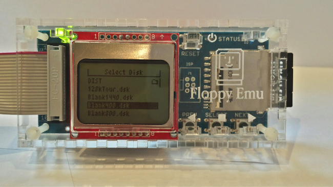
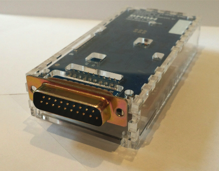
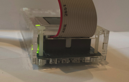
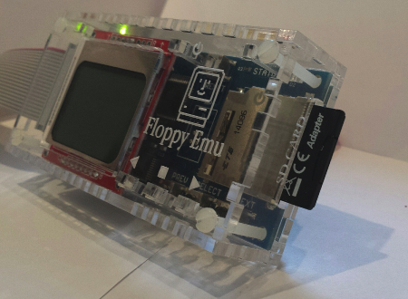
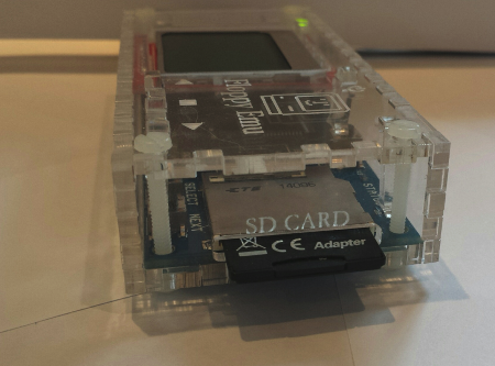
An official laser-cut case for Floppy Emu has finally arrived! It took a lot of prototyping and fiddling with tiny parts, but I hope you’ll agree the result was worth it. The case is only 6mm larger than the board itself, accommodates boards with the extension floppy connector or the built-in connector, and features light pipes to channel the LED’s to the outside of the case. The whole thing is cut from a single sheet of 3mm acrylic, and assembles like a 3D jigsaw puzzle.
I hope to offer these cases for sale soon, but I need help determining how many to make and in what colors. If you might be interested in a case, drop me an email or leave a comment below, and mention your color preference. Cases will probably be $19, and the color will be either clear or black.
Case Design
I was surprised how challenging it was to make a “simple box” case. My first plan was to design a 3D printed case, but I quickly abandoned that idea once I realized how expensive it would be. 3D printing is an impressive technology, but home 3D printers don’t really have the necessary reliability or speed for consistent manufacturing, and the material cost is significant. Online 3D printing services like Shapeways are another option, but they’re even more expensive. I also doubted I had the necessary 3D modeling skills to design a workable 3D case, so the idea never got very far.
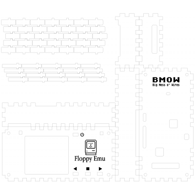
The best alternative seemed to be a laser cut case, constructed of multiple flat pieces assembled into a box shape. Adafruit’s laser-cut enclosure design tutorial was a big help, as was the web-based design tool MakerCase. Before I knew it, I’d designed a basic six-sided box of the proper dimensions, with finger joints at the edges to hold it together. But would it work? Designing a case using finger joints this way requires compensating for the kerf – the thickness of the laser cut. Assume a zero sized kerf, and the box won’t hold together. A 5mm wide tab will end up closer to 4.8mm wide after cutting, while a 5mm wide slot will end up closer to 5.2mm, and the tabs will sit loose in the slots. To compensate, the tabs in the design file should be slightly wider than the desired finished size, and the slots slightly narrower, but not too much. Overestimate the kerf, and the finished tabs will end up wider than the slots, preventing the parts from fitting together at all.
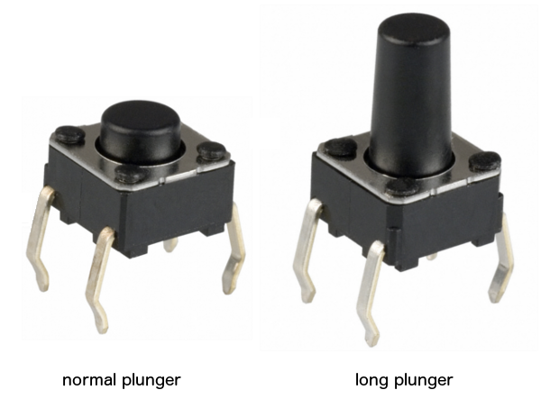
Next I added holes for case screws, the SD card slot, and the extension cable. Easy enough. But what about the buttons? Floppy Emu has four pushbuttons that are needed to operate it, so I couldn’t just seal them up inside the case. I could have cut a big finger-sized hole in the case lid above each button, so you could reach in and press it, but that seemed ugly and awkward. I could also have left the area above the buttons entirely uncovered, but that seemed even less appealing. If I were designing a product that was *always* in a case, I could have switched to a different type of push button with a long plunger that extended outside the case. But I’m not, and that would be goofy for everyone using a Floppy Emu without a case.
The Stick
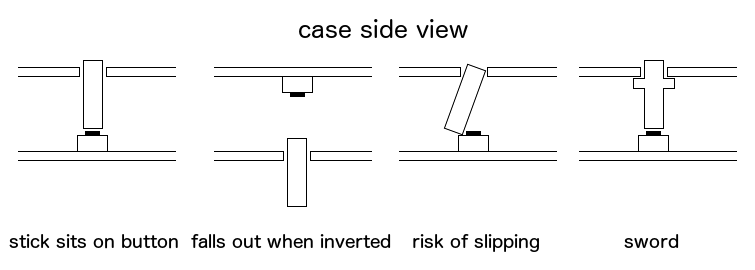
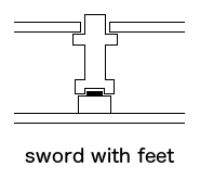
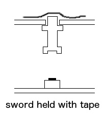
I finally concluded the only decent solution was to use some kind of stick to poke through a small hole in the top cover, and press the push button inside the case. This proved to be tricky to get right. If the stick were just a straight shaft, it would fall out if the case were turned upside down. And there was no positive force holding the bottom end of the stick onto the push button. It might wobble around or even slide off the button entirely, causing the whole stick to fall down inside the case. My solution was to add a crossbar to the stick to prevent it from falling out, turning the stick into a sword, and hoping that a tight fit between the sword and the hole would prevent it from sliding around. The light tubes used the same sword design, but modified in size to fit on top of an LED instead of a button. Voila! A finished design.
I sent the design file off to Ponoko for manufacturing, and about a week later I received the laser cut parts in the mail. With eager anticipation I separated the parts, fit them together, and bzzzzt! I had overestimated the kerf, and the parts didn’t fit together at all. Total failure. I went back to the design file, reduced the kerf estimate by half and made a few other mods, and sent revision 2 off to Ponoko. Another week passed. Finally I got the new parts, and it worked! Sort of.
The rev 2 case fit together, and the Floppy Emu board fit inside of it, so that much was looking good. But the swords had big-time slippage problems. They were too loose, and were constantly wobbling around or slipping down inside the case. For revision 3, I made the swords a bit thicker relative to the holes, so they’d fit more tightly and have less room to wobble. I also added “feet” to the swords, to help keep them centered on the buttons and LEDs.
Another week went by, and when the rev 3 case parts arrived, everything looked pretty good. The button swords still wobbled a bit, but not far enough to cause problems or fall off the button. The LED swords were more problematic, and sometimes wobbled off the LED’s centers, but generally stayed close enough to continue working as light pipes. Before offering these cases for sale I’ll probably do a rev 4 design to tighten everything up a little more, but rev 3 is definitely useable. Hooray!
Rev 3 also includes two alternate versions of the base and left side pieces: one for boards with a built-in floppy connector, and one for boards using the extension connector. That makes eight total side pieces, of which you’ll use six.
Sword Assembly
The only aspect of the design I’m not thrilled with is handling of the swords during assembly. How do you get those little buggers in there and aligned correctly, before you put the top on the case? You can’t just balance the swords on the buttons and then lower the top plate onto them – the swords won’t balance by themselves. One option is to assemble everything upside down: put the top plate upside-down on the table, then place the swords into the holes in the top plate, and finally lower the inverted Floppy Emu board onto the whole assembly. That works, but it’s pretty awkward.
The best solution I’ve found is to do assembly right-side up, and use tape to temporarily hold the swords in the top plate. You assemble the bottom and side pieces normally, and place the Floppy Emu board inside. Then you loosely cover all the top plate holes with tape, and push the swords up from underneath until their top surfaces touch the tape. Now you’ll be holding a top plate with all the swords dangling down under it. Finally, you lower this whole package onto the rest of the assembly, add the case screws, and then remove the tape. It’s not the most elegant system, but it works.
Colors
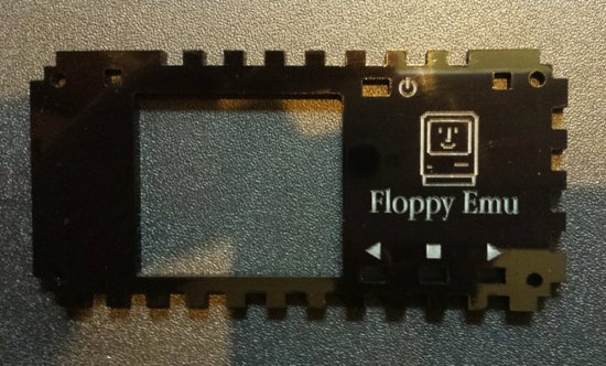
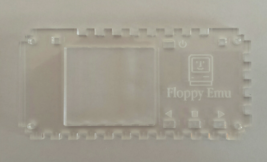
I originally planned to design the case in black, to give the final product a sleek iPhone-style appearance. But when I did a prototype in clear acrylic, my wife loved it and predicted it would be much more popular than black. One big advantage of a clear case is that it won’t need light pipes at all, since you can see the LEDs inside. The material is also a bit cheaper. But the etching on a clear case is difficult to see from some angles, and the final result with its exposed internals looks more like a science fair project than a professional product. What do you think? Which would you prefer?
Raspberry Pi 3D Performance Demo
I’ve recently gotten interested in 3D programming for the Raspberry Pi. I’m not sure why RPi 3D development interests me when desktop 3D mostly doesn’t – I guess there’s just something fun about coaxing as much 3D performance as possible from a little $35 device. Armed with 15-year-old Open GL experience and only slightly newer video game console dev experience, I set out to push the limits of the Raspberry Pi’s 3D hardware.
Finding the Right Yardstick
The first question I faced was how to best measure 3D performance. Does 60 FPS rendering of a single cube represent better performance than 10 FPS rendering of a complex scene? What should I measure, exactly? After mulling on the problem for a day, I decided the only decent metric I could measure was triangles per second. A cube is made of 12 triangles, and at 60 FPS that’s 720 triangles per second. A complex scene might consist of 100,000 triangles, and at 10 FPS that’s 1 million triangles per second.
Many 3D programmers argue that triangles/second is a useless metric, fundamentally flawed in its conception, because it ignores the fact that some triangles are much more expensive to draw than others. A large triangle is more expensive than a small one. A triangle with lots of textures and complex lighting shaders applied to it is more expensive than a solid blue triangle. Triangles whose outside faces are oriented away from the viewer, or that lie behind other previously-drawn triangles, are almost free. Increasing the screen resolution makes all triangles more expensive. There are so many factors that affect the cost of rendering a triangle, that comparing triangles per second benchmarks between different hardware platforms or different programs is virtually meaningless.
In the context of the same program drawing the same triangles on the same hardware, however, triangles per second is still a useful measure of relative performance. If a change to the program can increase triangles/second without sacrificing image quality somehow, then it’s a win. In fact, unless the API can access specialized hardware performance counters in the graphics processor itself, triangles/second and frames/second are virtually the only things it’s even possible to measure.
Building the Program
Over the course of a few evenings, I put together a demo program called rasperf3d, which you can download from the BMOW web site. My twin goals were to create an OpenGL ES sample program more complex than Raspberry Pi’s hello_triangle example, and to make a tool to measure the impact of screen resolution, model complexity, shader type, and other rendering settings on frame rate. The program draws many copies of the same model in a grid layout on the screen, and shows real-time rendering performance data including a measure of triangles per second. I can use the keyboard to change the current rendering settings, and see how it affects overall 3D performance.
For Raspberry Pi Programmers
The source code compiles on a stock install of Raspbian Wheezy, with no extra libraries needed. X Windows is not required nor used.
Some of the more interesting things demonstrated in the code are:
- Basic vertex and fragment shaders for Phong (per-pixel lighting) and Gouraud (per-vertex lighting)
- Using ETC1 compressed textures
- Rendering with vertex buffer objects
- Drawing text with a bitmap font
- Dynamically changing the screen resolution
- Dynamically enabling multi-sampling
- Taking a screen shot
Performance Measurement
Press S to hide all but the first row of text – this improves performance slightly. Use the keyboard to modify these settings:
- Number of objects rendered. Each object is 1 draw call.
- Type of object: Five choices, from a 12 triangle cube, to a 55K triangle robot.
- Screen resolution. From 1920 x 1080 down to 568 x 320.
- 4x Multi-sampling: on/off.
- Shader: textured with per-pixel lighting, textured with per-vertex lighting, untextured with per-pixel lighting, untextured with per-vertex lighting, flat colored.
- Texture filter: linear or nearest.
- Mipmaps: on/off.
- Backface culling: on/off.
- Depth test: on/off.
- Wireframe view: on/off.
- Camera distance away from the “wall of objects”.
- Camera yaw angle – view the wall of objects at an oblique angle, or edge-on.
- Camera look away – rotate the camera 180 degrees, so that all triangles will get clipped out.
- Secret feature: press R to take a screenshot.
For the curious: All the object models use one 256×256 compressed texture with mipmaps, and the same shader with one directional light, so the only performance difference between them is due to their geometry. All models have indexed verts. Each vertex has position XYZ, normal XYZ, and texture UV stored as 4-byte floats, for a total of 32 bytes per vertex. Rendering is done with VBOs (vertex buffer objects) and glDrawElements. Each copy of the model is a separate draw call to OpenGL.
Conclusions
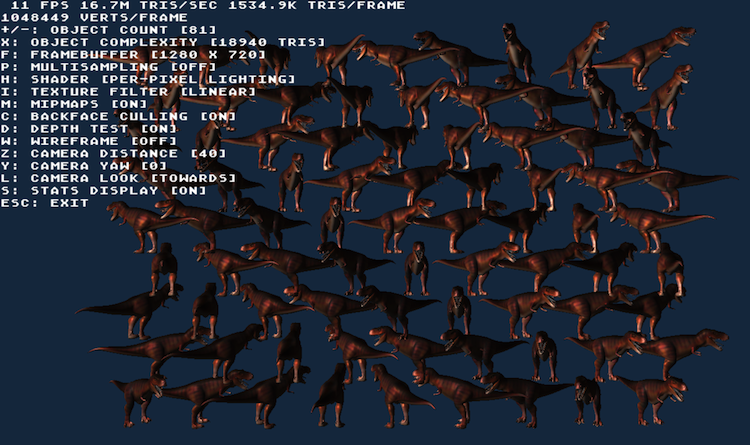
I was able to push the hardware as high as 16 million triangles per second, while rendering a dozen copies of a 19K triangle dinosaur model. This was on a stock Raspberry Pi, at a screen resolution of 1280 x 720, and with the texture and lighting settings mentioned above. Higher numbers are possible, but require using rendering settings that aren’t very realistic for a “real” 3D program. Absolute peak throughput was 27.3 million tris/sec with a very simple flat-colored shader, screen resolution of 568 x 320, and the camera pointed away from the objects so that all triangles were clipped.
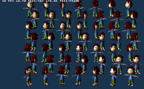
19K triangle object models are probably heavier than any real Raspberry Pi 3D game would use, since the hardware is only able to draw about a dozen of them before the frame rate dips below 60 FPS. Using a more appropriate model – a 500 triangle frog – the hardware was able to reach just 4 million triangles/second, but could draw 132 frogs before the frame rate fell below 60.
How does this compare to my PC or smartphone or Playstation? As mentioned earlier, direct comparison of triangle per second numbers between hardware platforms is generally meaningless. If I could run rasperf3d on a desktop PC or the Playstation 4, we might get a better relative comparison, but even that would be questionable. The program wasn’t designed to be a general purpose cross-platform 3D benchmark.
So I can’t put any specific numbers on it, but I feel comfortable in saying the comparison to modern 3D hardware is not favorable. That’s fine – that’s to be expected on a $35 computer the size of credit card. It’s been a very long time since I did any real professional 3D development work, but my recollection is the Gamecube, Xbox, and Playstation 2 games I worked on had scenes similar to my frog test. A typical scene in one of those games might have had something on the order of 100 objects, each of which consisted of a few hundred triangles, and used fairly basic textures and lighting. It looks like the Raspberry Pi should be capable of roughly the same.
Read more on this topic in the Raspberry Pi forums, here and here.
Read 1 comment and join the conversationBadUSB and the Hidden Microcontroller
BadUSB – what is it, and why is it scary? If you know something about microcontrollers and low-level electronics, the import of the recently-published BadUSB vulnerability is obvious and alarming. It destroys our nice little abstraction of external data storage being just a huge buffer of bytes, and reveals the microcontrollers and other control mechanisms underpinning it. And as it turns out, those control mechanisms have some properties that can turn them into a virtually unstoppable malware juggernaut.
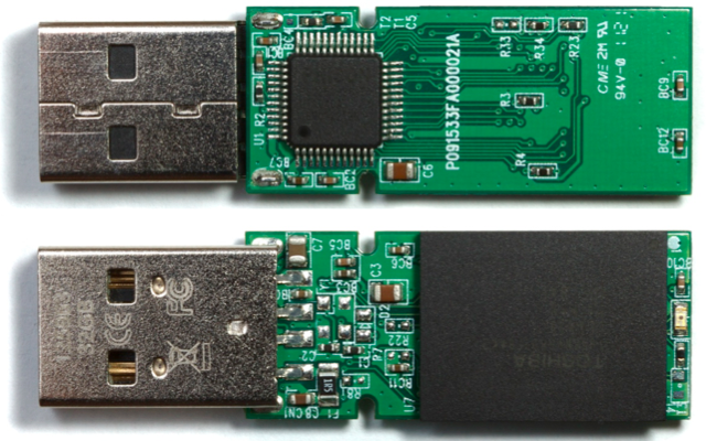
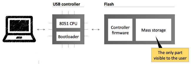
On every USB device from keyboard to thumb drives to web cameras, there’s a simple microcontroller that runs the hardware. It’s this microcontroller that actually talks to your PC, and processes keystrokes or fetches data from flash memory. Normally this microcontroller is invisible to the operating system and any programs running on the PC: they just send USB commands to the device, and get USB data back. The microcontroller is the invisible man in the middle, executing those USB commands.
Like your Arduino or any other microcontroller, the microcontroller on a USB device has its own simple control program called firmware. The firmware is authored by the USB device manufacturer, and is typically stored in a special non-volatile buffer in the microcontroller itself. But just like your Arduino, this firmware can be updated. And here’s where it gets scary.
A traditional piece of malware might scan your attached USB devices, looking for any that use a particular controller chip it knows how to infect. When it finds one, this malware could silently update the microcontroller firmware on that device. If the device is a USB thumb drive, the modified firmware might include a new behavior that does on-the-fly modification of every file retrieved from the thumb drive’s mass storage memory, attaching a virus. Boom! That thumb drive will now instantly infect any computer it’s plugged in to. But unlike a virus stored as a regular file in mass storage, it can’t be deleted. Erasing or reformatting the contents of the thumb drive will have no effect.
OK, that sounds bad. But maybe anti-virus programs could be upgraded to scan the firmware on attached USB devices and look for known evil USB firmware. Sounds good, but it’s not possible. The firmware of a USB device can typically only be read back with the help of that same firmware, if at all: A malicious firmware can spoof a legitimate one. For all practical purposes then, evil USB firmware is undetectable.
The range of possible exploits from evil USB firmware is very broad, and silently attaching a virus to every file retrieved from mass storage is just one example. Because the evil USB firmware can identify itself as a different type of device than it truly is, or even as a hub with multiple fictional devices, all sorts of crazy scenarios are possible. The researchers who first published the vulnerability described several possible exploits, including generating fake keyboard/mouse input, stealing passwords, redirecting network traffic, and even breaking out of a virtual machine.
At present, there appears to be very little that anyone can do to protect against this vulnerability, to detect it, or to remove it. A true fix would require a fundamental change to the way USB devices operate, and even then billions of older USB devices would remain vulnerable for years to come.
Read 1 comment and join the conversation