

Star Ring Version 2
Version 2 of my PCB-abusing LED blinky is here! It’s the same odd shape as Star Ring version 1, with the same abuse of the metal layer to make shiny stars and planets, and the same low power usage and long battery life, but it adds several small improvements to function and appearance. Sure, it’s just an LED blinky, but it’s got some interesting tricks.
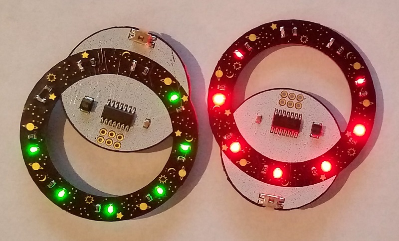
Version 2 replaces the amber yellow LEDs with either red or green. I’d imagined green would somehow be more exciting, but the red is a clear winner due to its much higher brightness. It’s not entirely obvious from the photo, but the red Star Ring has excellent brightness for something that’s driven from a puny 3V coin cell battery. The red LEDs have a 250 mcd brightness rating, as compared to 162 mcd for the amber LEDs and only 60 mcd for the green. From browsing the LED catalog, it’s clear that LED colors with longer wavelengths (closer to red) are able to achieve higher millicandela ratings at the same current and voltage. This is probably because of bandgaps and electron orbitals, or something… where’s a physicist when you need one?
Both the red and the green LEDs are 0603 sized SMD components, and they were my first-ever experience at assembling 0603 parts. Initially they seemed nearly microscopic compared to the 0805 size I use normally, and you could easily inhale one accidentally if you yawned at the wrong time, but I’m happy to report I didn’t have much difficulty with them. Each one is just 1.6 x 0.8 mm.
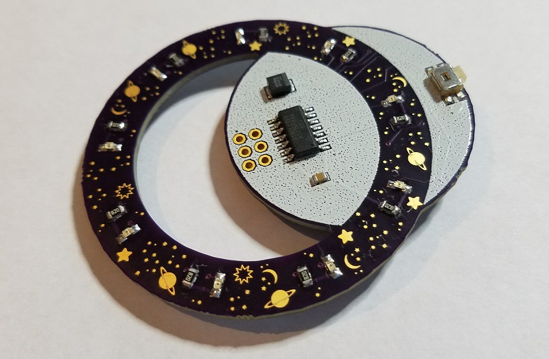
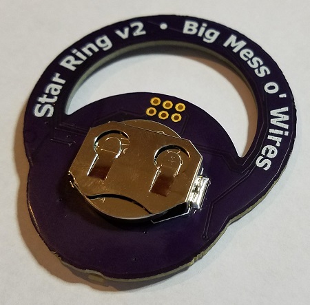
Star Ring version 1 located the battery on the front side, which was a little ugly. Version 2 moves the battery to the back, and brings the microcontroller and two capacitors to the front. It also fills the entire circular “moon” behind the star ring with white silkscreen, which really helps it to stand out visually. I think it looks great.
The tactile pushbutton was changed from a standard button to a right-angle button that’s mounted on the edge. Since it’s natural to hold the Star Ring by its edges, this makes it easy to hold the ring and push the edge-mounted button with a single hand. The version 1 Star Ring demanded two-hand operation due to its more awkward button orientation and placement.
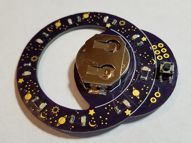
Version 1, for comparison:
Version 3?
It would be a tight fit, but there’s probably enough room to move the microcontroller and the button to the back, along with the battery. Then the front would only have a blank white moon and the star ring itself. That might look more attractive, but it would make soldering inconvenient, so I’m not sure it would be an improvement. Keeping all the parts (except the battery) on the front makes it easy to assemble the PCB using hot plate SMD reflow.
What about multi-colored LEDs? Full-color RGB is out of the question with this hardware, but what if each LED had a choice of two colors instead of being monochromatic? It’s possible to buy dual-color LEDs that are really two separate LEDs with a common cathode in a single package. A dual-color LED with red and green elements can appear red, green, or yellow depending on which of the two elements are illuminated. But dual-color LEDs would require controlling 18 LED elements instead of 9 – would I need a larger microcontroller with more IO pins? Fortunately no.
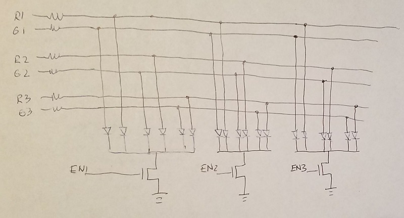
The current Star Ring hardware has 9 individually-addressable LEDs, with 9 current limiting resistors, connected to 9 IO pins of the microcontroller. The software never turns on more than three LEDs at once to avoid overwhelming the small battery, but it cycles through the LEDs so quickly that it looks as if they’re all on. Since it’s not necessary to power all the LEDs simultaneously, I worked out an alternative method where the same 9 IO pins could control 9 dual-color LEDs, organized into three groups of three dual-color LEDs each (six individual LED elements per group). Three IO pins are used to enable one of the three groups, and the other six IO pins control the six LED elements in that group. Only six current limiting resistors are required instead of nine, so even with the addition of three transistors for enabling the groups, the total component count is the same as the current design. Here’s my schematic for nine red-green dual-color LEDs:
4 Comments so far
Leave a reply. For customer support issues, please use the Customer Support link instead of writing comments.
Looks good!
Check into Charlieplexing. Drive n*(n-1) LEDs with n GPIOs.
Do you choose a random blink pattern on power-up? How do you seed your random number generator?
Finally, how about a touch-sensitive pad instead of a switch? Easier to operate on camera than the pushbutton. (-:
The time interval between button pushes is used as a random seed.
Just looked at the previous version’s post, and wondered if you’ve looked at using solder-down clothing-snaps as alternative button contacts? It would allow you to use embroidered circuitry to place the button wherever on the clothing that you felt appropriate.
Also, have you looked at scavenged power from an LED? I wouldn’t do it with the LEDs you have now (or, rather, I’m not doing it with the charlieplexing on one of my projects), but if you added the satellites idea suggested on the other page via directly driven through-hole LEDs, then you might be able to get indefinite endurance via a jfet-driven hartley oscillator with extra diode and inductor for boost behavior.
Never mind, your schematic actually looks similar to what I’ve sketched out for my direct driven LEDs that I’m going to use for power scavenging. I just added a bunch of Schottky diodes.