

LED PWM Without Resistors
I’ve been working on version 3 of Star Ring, my fun but useless circular LED blinker, and I had an idea. Do I really need current-limiting resistors for the LEDs? Or can I effectively control the LED current using PWM?
Normally a resistor is always needed in series with an LED. Without the resistor, a very high current would flow, destroying the LED. The max DC forward current is specified in the LED datasheet, and is typically something like 30 mA. Often the datasheet will also specify a peak forward current, higher than the DC max, for applications where the LED is rapidly switched on and off with PWM. But how can I calculate what the current will be, if there’s no resistor? As usual, the answer is in the datasheet.
Star Ring is an ATTINY84A microcontroller powered by a 3V CR2032 watch battery. For the sake of this analysis, we’ll assume I’m using this Lite-On dual-color LED with independent red and green elements. The datasheets for the microcontroller and the LED both include graphs of voltage vs current:
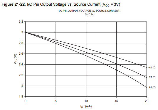
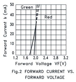
The more current that’s drawn from an ATTINY I/O pin, the more the voltage will sag below the 3V supply. And the more current that’s passed through the LED, the more the voltage across it will rise. At some point these two graphs will intersect. You have to exchange the X and Y axes of the LED graph, and extrapolate the ATTINY graph a little, but for the green LED the crossing point is about 2.0V at 25 mA. In the absence of any current-limiting resistor, that’s what you’ll get – theoretically.
25 mA is below the LED’s 30 mA max current rating, so that’s fine. It’s also below the ATTINY’s 40 mA max current per I/O pin, so that’s fine too (although it’s curious why the ATTINY IV graph only goes up to 20 mA). So for this combination of hardware, it looks like current-limiting resistors aren’t needed at all. If 25 mA is more current than is desired, PWM can be used to reduce the average current to something lower.
In reality, the DC current without a resistor will be lower than 25 mA, because of the internal resistance of the CR2032 battery, which I’ve estimated is something like 13 ohms. At 25 mA, even with a fresh 3V battery, the supply voltage to the ATTINY will only be 2.675V due to the battery internal resistance. The I/O pin output voltage will sag further below 2.675V, and those two IV curves will cross at a different point with a current lower than 25 mA. A simple experiment could find the exact number.
Ignoring My Own Advice
Despite this conclusion, I’m probably going to keep the current-limiting resistors, for a few reasons. The graph for the red LED is different than the green, and the no-resistor current will be higher, potentially at an unsafe level. I’m also uncertain whether 25 mA is really OK for the ATTINY – it’s below the 40 mA absolute max rating, but the rest of the datasheet implies 20 mA is the recommended maximum, and there’s no max continuous vs peak current distinction I can see for the I/O pin. I’m also concerned about what happens during debugging or a software crash when my PWM code unexpectedly stops running, and the LED is left constantly on until I can manage to do a reset or kill the power. The resistors will provide some valuable insurance, even if they’re not absolutely required.
Read 1 comment and join the conversation1 Comment so far
Leave a reply. For customer support issues, please use the Customer Support link instead of writing comments.
Thanks for the info, i’ll keep my resistors then 🙂