

Limiting SD Card Inrush Current
I’m experimenting with methods to limit the inrush current when an SD card is inserted, and beginning to wonder whether my solutions are worse than nothing.
When an SD card is inserted into a board that’s already powered on, a large amount of current will flow briefly, as the card’s internal capacitors are charged through its 3.3V supply pin. This is called inrush current. If the inrush current is too large, it can overtax the main board’s voltage regulator and capacitors, causing the board’s supply voltage to drop temporarily. If the voltage drops far enough, it may cause the board’s microcontroller to do a brownout reset. That’s what happened with early versions of the Floppy Emu. It wasn’t really a problem, because you’ll almost always want to perform a reset anyway after inserting a new card, but it was slightly annoying.
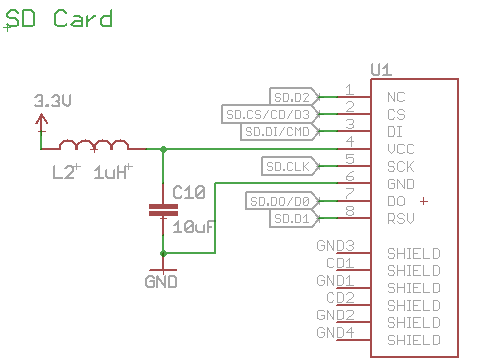
In later versions of the Floppy Emu, I added a 1 uH inductor and 10 uF capacitor for the SD card, as shown in the circuit schematic above. Later the capacitor was changed to a 33 uF tantalum. The purpose of the inductor was to limit the inrush current, preventing the main board’s supply voltage from sagging and causing a brownout. And it worked, mostly, as confirmed by observing the main supply and SD card supply voltages on a scope during card insertion. The exact behavior depended on the brand and type of SD card and the card’s internal circuitry. Some types of cards still caused a brownout reset when hot-inserted, but it was rare.
Revisiting this question again recently, I noticed that the inductor created a new issue that may be worse than the one I was trying to solve. When the SD card is inserted, its 3.3V supply pin doesn’t go cleanly from disconnected to connected. Instead it bounces and wiggles over a period of microseconds to milliseconds, just like the contacts of a mechanical switch. As a result, the inrush current isn’t one single burst, but a series of short on/off current pulses. Because of the presence of the inductor in the circuit, these pulses create voltage spikes on the SD card’s 3.3V supply pin. They’re brief – lasting about 100 ns – but some of the spikes go above 4V. Despite their brevity, I’m wondering if they’re high enough to damage the SD card.
Using an inductor seems to be a pretty standard solution for SD card inrush current, but I’ve never seen any discussion of the voltage oscillation and spikes this can cause for the card’s supply. An alternative is a power management IC with “soft start” behavior, but I’m not interested in adding extra chips in this case. I’m starting to think it may be best to remove the inductor, and connect the card’s 3.3V supply directly to the board’s 3.3V supply. Better to cause a nuisance brownout due to high inrush current, than to risk damaging the card with voltage spikes – and still have brownouts sometimes anyway. Have you ever dealt with this topic? How did you address it?
Read 16 comments and join the conversation16 Comments so far
Leave a reply. For customer support issues, please use the Customer Support link instead of writing comments.
I’ve used the TI TPS208x’s in the past for exactly this problem and they’ve worked beautifully. Fortunately these are very cheap and come in a variety of footprints that aren’t too bulky. I definitely understand the hesitation – dealing with external devices can be a serious pain without them though.
Hmm, all the open source hardware examples I checked connect the SD card’s 3.3V supply directly to the board’s 3.3V supply. None of them use an inductor or any power management circuitry like the TPS208x. I looked at several hardware examples that include a microcontroller and an SD socket: Teensy 3.5 and 3.6, Teensy Audio Adapter, Arduino Ethernet shield, Sparkfun Logomatic, Sparkfun GPS Logger Shield, LiliPad MP3, Raspberry Pi Model B rev 2, Adafruit Feather M0 Adalogger, Micropython pyboard, and Beaglebone Black. The Beaglebone uses a second 3.3V supply for the SD card and a few other components. All the other boards appear to use a single 3.3V supply for everything including the SD card. So I’m not sure how they handle hot insertion, but I assume they don’t. It looks like the inductor may have been the wrong idea.
Wait, something doesn’t make sense here. The Floppy Emu’s microcontroller runs at 5V, supplied directly from the attached computer. Even if hot insertion of the SD card caused the board’s 3.3V supply to sag low temporarily, that should only affect the other components that use 3.3V. The 5V microcontroller should be unaffected and shouldn’t experience brownout or reset… but it does. The chip’s brownout detection is actually disabled, and it can run at supply voltages as low as 1.8V, so it seems pretty darn unlikely that the 5V supply is being pulled all the way down to 1.8V due to inrush current provided from the 3.3V regulator during SD card insertion (I will test it). So maybe the microcontroller reset isn’t caused by a sagging supply voltage at all, but by something else. Mysterious.
Interesting. Is it possible that you’re current limited on the 5V supply? It might be worth isolating that rail and supply power via a DC power supply to look at total current and also provide a deeper source of power to verify your brownout theory.
It may need more bulk capacitance on the board for 5V. The board is at the end of a 1-meter ribbon cable, so the computer’s 5V supply can’t respond very quickly to changes in current. When an SD card is hot inserted, the 3.3V supply gets pulled down *and* the 5V supply that feeds the board’s 3.3V regulator also gets pulled down. Both supplies get briefly pulled down by about 0.3 to 0.6V. But even if the 5V supply gets as low as 4.3V, that’s nowhere near low enough to cause a microcontroller reset or malfunction.
Something strange: I tried two Floppy Emu boards, and one consistently exhibited twice as much voltage drop as the other when an SD card was hot inserted. The “good” board dropped by 0.3V before recovering, and the “bad” one dropped 0.6V. The bulk capacitors have 20% tolerance, so if one board has caps that are 20% above the nominal rating and the other board has them 20% below, that might explain part of it.
Another something strange: I couldn’t reproduce the effect I saw yesterday where hot insertion of the SD card causes a microcontroller reset. Yesterday it was happening very frequently. Today I only got it to happen once, and I didn’t have the scope ready to measure the voltage. I’m beginning to suspect the resets aren’t caused by the supply voltage drop, which seems far too small to cause that. Maybe I was delivering a static shock when I reinserted the card, or maybe one of the scope probes brushed the reset pin, or some other coincidence.
If you\’re worried about the 3.3V supply rebounding above normal, you can add a fast diode across the inductor to clamp the over voltage. I know, another component. Sorry.
I’d drop the inductor entirely & just add more bus capacitance – both at the 5V input and next to the microSD card. You can never go wrong with more buscap.
Does the microSD socket you’re using have a “card present” contact you could use to trigger a soft-start circuit?
What do you suggest as a good value for bus capacitance? Right now there’s 33 uF on 5V, 33 uF on 3.3V, and 33 uF on the SD card’s private 3.3V (which is just the main 3.3V supply separated by the inductor). They are all tantalum caps. The board never uses more than about 200 mA, except briefly during hot insertion of the SD card.
This is beginning to look like a big fuss over nothing. I desoldered the inductor and replaced it with a wire, so the SD card’s VCC is directly connected to the main 3.3V supply. It wasn’t dramatically different than with the inductor. Without the inductor, the supply drops a few more tenths of a volt when the SD card is hot inserted, but it’s still not enough to cause a MCU reset. The worst case I saw was a drop to 2.44V, vs a drop to 2.8V with the inductor in place. Adding 47uF more of bulk capacitance helped a little – reduced the size of the drop by 0.15V. There’s more variability from board to board, or even between different test points on the same board, than there is between the with-inductor and without-inductor versions.
Instead inductor maybe you can use PTC (as most powers supplies does). Anyway, simple solution is more capacitance.
The inductor should definitely go, I can’t see it doing anything useful other than causing weirdness.
I’d be running about a 110uF cap on the 5V bus and a 47uF on the 3.3V at minimum – a brief search around suggests you need about 45uF minimum on the 3.3V to deal with inrush current on a microSD (varies from card to card and manufacturer to manufacturer), or to use a MOSFET with a soft-start circuit to wake it up – but that’s even more components and kind of silly.
Also, I forgot to add – maybe make your power traces wider on the PCB?
Hi Steve,
I use a PI filter consisting of 100nF (ceramic) closest to SD Card, then 10 uF (ceramic), then BLM18BB151SN1D Ferrite Bead, then 100 nF (ceramic). Hope you can picture it 🙂
The Ceramic has lower ESR than Tantalum. On the SD Card side, I measure a 500 mV drop on insertion, but on the +3V3 bus side, I measure only 200 mV drop. Test performed with Verbatim 8GB Class 10 MicroSD card. Maybe normal SD cards have more room for internal caps and subsequently the drop will be larger?
Regards,
Pieter
P.S. I used my multimeter and measured 1.8 uF of capacitance on the MicroSD card’s power supply pins.
I just always considered it to be against the rules to insert/remove the SD card of my Floppy Emu while it was on!
It is possible to solve this problem with passive circuits alone, but you would rather use some active devices.
You want to use a pass transistor in between the board’s 3.3V net and the SD 3.3V net. Then when the card detect signal becomes active, manipulate the base/gate of the pass transistor to slowly turn on the power to the SD card. Okay but that’s fiddly and uses a lot of components. You want an inexpensive chip that does something similar. You also want to limit current into the card during operation, not just during hot-plug, as well as cut off the power completely if a short circuit persists for more than a few milliseconds. There are current-limited switches for USB and similar applications that have all of these characteristics. You should look into those. Texas Instruments has a lot of good chips in this category.
Now back to the passives. Alright, NTC fuses are passive, but I reject them for this purpose since they don’t really work twice in rapid succession. You can solve this problem with RLC circuits only.
Method 1, series damping:
Use the inductor and cap as you show in the schematic, but add a resistor in series with the inductor. A resistance on the order of sqrt(L/C) provides close to critical damping. It’ll be something like half an ohm. With 1uH and 10uF, you have like 50kHz oscillation frequency. You are thus adding the additional attenuation of the ~0.5ohm and 10uF RC filter, which has a cutoff frequency of 30kHz.
Problem is, you pay for the resistance with DC voltage drop. If you can tolerate the voltage drop, this is the cheapest way to ensure you have a damped circuit. This damping strategy is not so good for power circuits, although you can of course use it for micropower stuff.
Shunt damping idea:
Imagine your SD card has a dead short in it. Then the oscillation wouldn’t occur, right? The oscillation is caused by the interaction of your inductor and the power capacitance of the SD card. The capacitance is irrelevant if the load has a low enough DC resistance. The idea in achieving critical damping is that all of the energy built up in a cycle of oscillation can be dissipated in the same amount of time. So what you can do is provide a dummy load on your board. Put a resistor, again on the order of sqrt(L/C), in parallel with your 10 uF cap on the SD card side. This sort of throws away any extra energy that would develop into a resonant oscillation.
But now there’s an even worse problem… If you need 0.5 ohms of shunt damping resistance, you will waste 6.6 amps! We traded voltage drop for wasting current, and we got a really bad deal too. This is no good, but we are almost there.
Method 2, AC shunt damping:
We almost had it with the last idea, but the problem was that even in the absence of wacky oscillations, DC power was still wasted. So we can modify the shunt damping strategy slightly. Instead of just a shunt resistor, also use a capacitor to block current at DC. Thus the dummy load only draws current when the microSD’s voltage is changing. The key is, you’ve gotta size your capacitor something like 5-10x larger than the total capacitance on the microSD side of the inductor. That includes your 10uF cap as well as the capacitance on the microSD card.
So consider switching to a small 0.1uF capacitor in parallel with the series combination of 0.5ohms and 22uF. Then any loads with a capacitance of less than 5uF or so are critically damped or overdamped.
Hi,
I have an question, SD series have WP switch, how is WP switch working inside connect from which pin to pull up or pull down in SD Card case?