

Cortex M4 Interrupt Speed Test
How quickly can a microcontroller detect and respond to changing inputs? Fast enough to replace a dedicated combinatorial logic chip, like a mux? I finally have some test results to begin answering this question.
My goal here is a potential redesign of the Floppy Emu disk emulator. The current design uses a microcontroller for the high-level logic, and a CPLD for the timing-critical stuff. But if a new microcontroller were fast enough to handle the high-level logic and the timing-critical stuff, I could simplify the design and eliminate the CPLD.
This is the fourth post in a series:
1. Thoughts on Floppy Emu Redesign
2. Thoughts on Low Latency Interrupt Handling
3. More on Fast Interrupt Handling with Cortex M4
Background
Let’s consider a mux-like function performed by Floppy Emu’s CPLD, as part of some disk emulation modes. It behaves like a 16-to-1 mux: 16 data inputs, 4 address inputs, and 1 data output. In order to properly emulate a disk drive, the mux must respond to changing address or data inputs within 500 nanoseconds. For my tests, I used an ARM Cortex M4 running at 120 MHz: specifically the Atmel SAMD51 on an Adafruit Metro M4 Express board.
At 120 MHz, 500 nanoseconds is 60 clock cycles: that’s how much time is available between an input’s rising/falling edge and the updated data output. The previous posts in this series examined the datasheets and performed some static code analysis, attempting to decide whether this was realistically possible in 60 clock cycles. The answer was “maybe”, awaiting some real-world timing experiments.
Timing It
Here’s a very simple interrupt handler. It doesn’t even attempt to perform the 16-to-1 mux function yet. It sets an output pin high when the handler begins running, and low when it finishes running, so I can monitor the timing with a logic analyzer. The body of the interrupt handler clears the interrupt flags for external interrupts 1, 2, 3, and 6 (where I connected the address inputs). This establishes a lower bound on how fast the real interrupt handler could possibly be, once I’ve added the 16-to-1 mux functionality and many other related pieces of logic.
void EIC_1236_Handler(void)
{
	PORT->Group[GPIO_PORTA].OUTSET.reg = 1 << 2; // PA2 on

	uint32_t flagsSet = EIC->INTFLAG.reg; // which EIC interrupt flags are set?
	flagsSet &= 0x4E;  // we only act on EIC 6, 3, 2, and 1
	EIC->INTFLAG.reg = flagsSet; // writing a 1 bit clears the interrupt flags.

	// now do something, based on which flags were set. More flags may get set in the meantime...

	PORT->Group[GPIO_PORTA].OUTCLR.reg = 1 << 2; // PA2 off
}
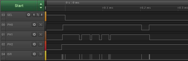
Here are the results from the logic analyzer. The inputs PH2, PH1, PH0, and SEL are from a Macintosh Plus querying to test whether a disk drive is present. ISR is the timing output signal from my interrupt handler.
Every time there's an edge on one of the input signals, there's a brief spike on ISR. Looks good. Let's zoom in:
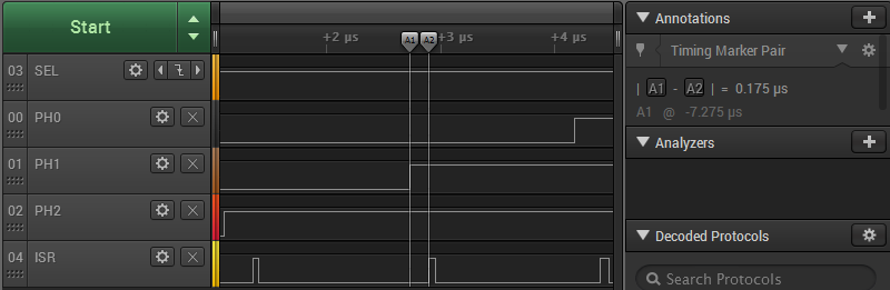
For the highlighted input edge, the delay between a rising edge of PH1 and the start of the interrupt handler is 175 nanoseconds (0.175 µs). Other edges are similar, but not identical. For this sample, the delays ranged between 175 and 250 ns. The width of the ISR pulse (the duration of the interrupt handler) was either 50 or 75 ns. So the total time needed to detect an input edge and run a minimal interrupt handler function is about 225 to 325 ns. That only leaves a few hundred nanoseconds to do the actual work of the interrupt handler, which doesn't seem promising. (The precision of the timing measurements was 25 ns.)
Test conditions:
- NVRAM line cache was enabled
- NVRAM wait states set to "auto"
- L1 instruction/data cache was enabled (it's about 1.6x slower when disabled)
- edge detection filtering and debouncing were off (these add latency)
- edge detection was configured for asynchronous (fastest)
- the main loop never disables interrupts
- SAMD51 main clock was definitely 120 MHz (confirmed with a scope)
This result is moderately worse than predicted by my static analysis of code and datasheets. Through further tests, I also found that code in my interrupt handler averaged close to 2 clocks per instruction, not the 1 clock per instruction that I'd hoped. That makes sense, because apparently any Cortex M4 instruction that references memory requires a minimum of two clock cycles. When I began writing the 16-to-1 mux code, the duration of the interrupt handler quickly approached 500 ns all by itself, without even considering the delay from input edge to start of the interrupt handler.
What Next?
Given these results, I'm almost ready to give up on this idea, and return to the tried-and-true CPLD-based solution. I say "almost", because I haven't yet written the full 16-to-1 mux functionality and other related logic, and because there are still a few more tricks I could try:
- relocate the interrupt vector table from NVRAM to RAM
- relocate the interrupt handler itself from NVRAM to RAM
- overclock the SAMD51 or try a different microcontroller
- profile various Macs and Apple IIs, to see if there's any slack in the 500 ns nominal requirement
But at this point, my intuition says this is not the right path. The whole idea of moving timing-critical logic from a CPLD to the microcontroller was to simplify things. There's no reason I must do this - it's just an option. So is it really simplifying things if I need to throw every optimization trick in the book at this problem, just to barely maybe meet the 500 ns timing requirement with no room to spare? What happens when I discover some future bug or requirement that needs a few extra instructions in the interrupt handler, and now it's pushed over 500 ns? Is it really worth abandoning all the time I've spent getting familiar with Atmel's SAM hardware and tools, in order to try some other vendor's part that goes to 150 MHz or 180 MHz? Probably not.
Relying on both a CPLD and a microcontroller surely has some drawbacks: a two-part firmware design, larger board, and slightly higher cost. But it also has a huge benefit: it's a much surer path to getting something that works. I've already done it with the existing Floppy Emu design, and I could make incremental improvements by keeping the same basic approach, but replacing the current CPLD and microcontroller with newer alternatives. I'll stew on this for a while more, but that's where it feels like this is headed, and I'm OK with it.
Read 10 comments and join the conversation10 Comments so far
Leave a reply. For customer support issues, please use the Customer Support link instead of writing comments.
Hello, have you considered polling instead of using interrupts ?
See here for a project with similar (I think) constraint : http://spritesmods.com/?art=veccart
With polling, there would be no time to do anything else with the microcontroller. I was hoping to make the MCU perform the timing-critical logic in an interrupt handler, while still doing the high-level emulation logic in the program’s main loop.
Did you try with a main loop that flushes the instruction cache? For worst-case timing, you want to analyze the case where the interrupt handler is not in the instruction cache.
Also consider the case where two address inputs change at almost the same time. If you’re unlucky, you’ll still be spending time processing the first change when the second happens, delaying the second interrupt that is actually important.
On the other hand, I would assume that the actual work of the interrupt handler would be pretty minimal if all the possible outputs are precomputed (perhaps as 16 bits in an integer?).
Another crazy idea: If you need a 16-to-1 mux, why not use one as a separate part? Of course, then you need 16 I/Os to provide the values (plus another 4 if you still need the address inputs), but you won’t have to worry about timing.
The exact behavior of the mux depends on which emulation mode is chosen, so unfortunately it can’t be a fixed piece of hardware. Also the mux isn’t the only piece of timing-critical code, it’s just the most obvious one. So even if a discrete mux were possible, there would be other timing-critical code with similar constraints.
The questions about instruction cache and near-simultaneous input changes are the stuff that gives me nightmares, and makes me think this approach just isn’t the best path forward. That’s why I’m leaning towards keeping a CPLD in the design – I know that approach works because I’ve already done it successfully.
I believe the Flash Floppy project (https://github.com/keirf/FlashFloppy) targets around 400ns via interrupt timers and DMA on STM32 hardware (cheap gotek floppy emulators). Some details on timing in https://github.com/keirf/FlashFloppy/blob/61f73bdec1c79d2d6ce08841359dda9e01d95ea8/attic/timings.txt
Excuse me, please give me your e-mail, thank you.OvO
I know people have relocated their interrupt vector table and code into ram on PIC32…. Actually I think that might be how chipkit does it by default but I haven’t checked otherwise you pay a significant performance penalty for accessing flash.
You might be able to use a PIC32 that has a Configurable Logic Cell (CLC). In the 4 Input AND mode with the appropriate inversion (or using multiple cells), you could implement a 16 to 1 mux that takes constant data.
The PIC32MM0256GPM064 is one such part that contains a CLC.
well,
I actually wanted to write a longer comment about how I think this is maybe possible to do – and I think it might be – but
decided to delete the reasoning because I also think it\’s not advisable for various reasons. Esp. weird corner cases and
slight cycle changes due to \’whatever\’ (caches, other int., flash delays..) that will be harder to debug and take time to figure out.
And it\’s at the boundary of what you can get up and running at 120 or better 168MHz with interrupts and hand-written asm code
anyways if you figure in additional cycles for likely error handling.
I myself am using an STM32F4 for hw emulation in multiple projects for years now so have seen my fair share of weirdnesses,
Thomas
p.s.
if you haven\’t seen this – here someone did an int.-driven emulation of a gameboy cart.:
https://dhole.github.io/post/gameboy_cartridge_emu_1/