

Halloween LED Matrix and PSU Death
In preparation for Halloween this year, I built a large and colorful LED matrix. After programming it with monster-themed animations, it looked fantastic! Months passed, and when October 31st finally arrived, at dusk I hung the LED display outside by the street. It was to be the perfect lure for neighborhood kids.

But when I checked back an hour later, the LED display was dark and dead. Halloween passed in sad form, with no display of animated monsters. What happened?
LED Matrix ‘Hello World’
This all started last May, when I bought a generic 64 x 32 LED matrix from eBay. These matrix displays are designed to be controlled by an Arduino, Raspberry Pi, or other microcontroller or FPGA. The smallest displays are the simplest: the control unit selects one row of LEDs to illuminate, and then sends a stream of 0’s and 1’s to turn off or on the individual LEDs in that row. In effect, each row of the display is like a large shift register, with each bit corresponding to a separate LED. By cycling rapidly through all the rows, and providing different data for each row, the control unit can create the appearance of the whole LED matrix being lit. For larger displays, two rows can be illuminated at once, using two separate streams of bits, but otherwise the interface is the same.
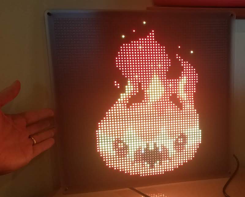
A blog post from May describes my experiences with that first 64 x 32 LED matrix, using custom software I wrote for an Arduino. It worked well, and the matrix was impressively bright and colorful – the photos can’t do it justice. My custom software was limited to displaying static images, with only 8 colors, because the red, green, and blue LEDs were simply on or off with no in-between state.
Matrix Upgrade
If one matrix is good, two matrixes must be better! I bought a second identical matrix and connected it to the first. These matrixes are designed to be daisy-chained, with the shift-out from one matrix connected to the shift-in of the next. Logically this results in rows that are twice as long as before, creating a 128 x 32 matrix. But physically I arranged the displays to create a 64 x 64 matrix. As a result, the control software became more complicated with mappings between physical and logical lines.
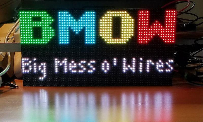
I quickly abandoned my custom Arduino solution, and adopted the excellent rpi-rgb-led-matrix Raspberry Pi library by Henner Zeller. It’s incredibly rich, supporting many different physical to logical mappings, thousands of colors using PWM, video playback, and many other advanced features. Really, if you’re experimenting with one of these LED matrixes, this is the software you want.
For the Raspberry Pi, I selected a Zero W thanks to its built-in WiFi, small size, and rock-bottom price of $10. The OS is a default Raspbian image configured to run in terminal mode. It’s easy to connect to the Pi over WiFi using ssh, and then use rpi-rgb-led-matrix command-line utilities to display images on the LED matrix. It’s a powerful solution, and the only downsides compared to the Arduino are the few seconds required for the Pi to boot up, and the need to perform a clean shutdown instead of just pulling the power plug.
It’s possible to connect the LED matrix directly to the Pi’s GPIO pins, if you don’t mind a squid-like mass of wires. I chose an easier route and bought the Adafruit RGB Matrix Bonnet, which has the same footprint as the Pi Zero and makes the LED matrix connections a breeze. I performed a simple mod to the Adafruit bonnet in order enable hardware PWM to reduce flickering, as described further here. After that it was just plug and play, using the --led-gpio-mapping=adafruit-hat-pwm command-line switch for the rpi-rgb-led-matrix software.
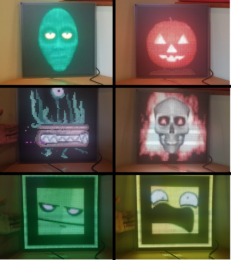
Using the advanced search tools from Google Images, I looked for 64 x 64 animated GIFs with monster-related keywords. In short order I was able to locate several dozen. I was in business!
Building the Frame
To mount the two LED matrix panels together and create an eye-catching display, I built a custom frame. The design was loosely based on this Instructable by Al Linke. It uses several layers of laser-cut acrylic with a pile of carefully-sized spacers and machine screws. The frame took a substantial amount of work, but the end result looks great.

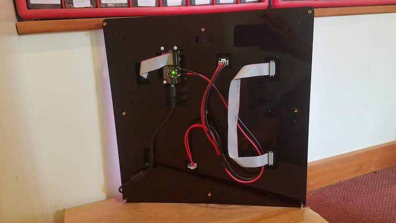
First the LED panels were mounted on a black acrylic piece, with pre-cut holes for mounting screws, wiring, and the Raspberry Pi. The rear of that piece was an ugly and bumpy tangle of cables that wouldn’t hang flat against the wall, so a second black acrylic piece was mounted behind the first to contain the mess. This piece also has integrated mounting holes for a wall hook or picture hanging wire. A third semi-frosted acrylic panel was then mounted on top, to give the LEDs a more diffused look. This is matter of taste, but I found that the LED images looked much nicer with the diffuser panel than without.
Powering the LEDs
In a 64 x 64 matrix, there are 4096 elements. Each element contains separate red, green, and blue LEDs, so the grand total is 12288 LEDs. Assuming that each LED draws 15 mA (a typical number for a single discrete LED), naive math calculates the total current as a whopping 184 amps! Ouch! But this calculation overlooks the fact that only a few rows are actually illuminated at the same time. This particular matrix uses 1:16 multiplexing, so the maximum current is a much more manageable 11.5 amps.
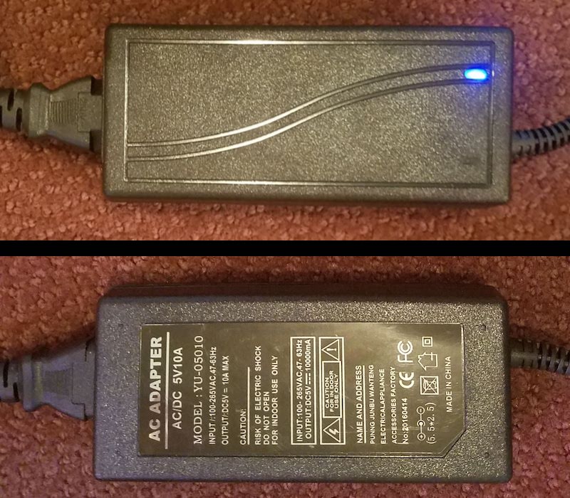
Armed with this information, I purchased the 5V 10A power supply shown here. Why only 10A instead of 11.5A or more? Enclosed “brick” supplies that can provide more than 10 amps are difficult to find, and I expected I’d never need 11.5 amps anyway for real-world images. 11.5A is a worst-case number for a solid white image where every LED is on. My halloween monster images are much darker, typically with many black pixels, so the required current should be much less.
Failure Analysis
When the LED display died on Halloween night, the Raspberry Pi was unresponsive to WiFi connections and the LEDs were dark. The power indicator on the Pi was blinking on and off. Later I noticed that the blue power indicator on the power supply brick was also blinking on and off. Strange.
I brought everything inside and plugged it back in, with the same result. Nothing worked, and the power indicators blinked. At first I thought there must be a short-circuit somewhere in the LED matrix or the Adafruit bonnet, which was repeatedly tripping some protection circuitry in the power supply. But when I disconnected the Pi and the LED matrix, and tried the power supply alone, I observed the same blinking power indicator. The problem was clearly with the power supply itself. Did I exceed its maximum current rating and kill it?
Confused, I left the hardware unplugged for a few days. Later, when I plugged it in again to begin more troubleshooting, I was surprised that it worked! I reconnected the LED display, and everything was great for about an hour. Then it died a second time, with the same blinking power indicator symptom. Uplugging and replugging didn’t help. But if I left it unplugged for a few hours, it would work again the next time it was plugged in.
By this point I was fairly sure I must be over-taxing the power supply and drawing too much current. I guessed that the supply must contain a thermal fuse, and it was overheating and shutting down. Only after a few hours of cooling would it work again, for a short while. 10 amps was simply not enough, it seemed.
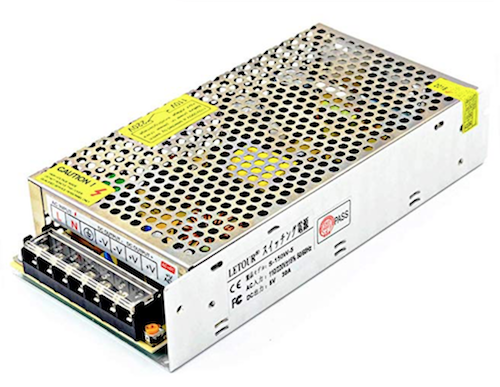
To solve my power needs I purchased this 5V 30A “cage” type supply. I was reluctant, because this type of supply isn’t meant for outdoor use, and because it requires wiring to screw terminals instead of using standard power plugs. I’m a reasonably careful person, but I still get nervous playing with bare wires that carry mains voltages. Unfortunately I didn’t see a good alternative.
Before connecting the 30A supply, I decided to do one more test to see how much current the 10A supply was really using. I don’t have an easy way to directly measure the DC current, so I used a Kill-a-Watt meter to measure the power delivered from the wall outlet to the supply. I cycled the LED matrix through its collection of monster images several times, and the highest power measured by the Kill-a-Watt was 19 watts. Hmmm. If I assume the power supply is 80% efficient, then that means it was supplying about 15 watts to the LED matrix. It’s a 5V supply, so that’s a current of only 3 amps maximum – far below the supply’s claimed max of 10 amps. So why did the supply keep shutting off after an hour of use?
While still connected to the Kill-a-Watt, I let the hardware run for a while. This time it took several hours before it shut down, but the end result was the same as before, with dark LEDs and a blinking power indicator. The Kill-a-Watt showed 1 watt. The power supply didn’t feel hot to the touch, but was only slightly warm. This seemed to rule out my “overheating” theory, but didn’t suggest anything else.
Because I’d measured the max current at only about 3 watts, I decided to try a new approach. I pulled out another brick-type power supply from a different project, this one rated at 5 volts and 4 amps max. I connected it to the LED display, and started everything running. It worked just fine, and 18 hours later it’s still running smoothly. Success! At least for this series of Halloween images, it’s all I need.
I’m still curious what caused the first power supply to fail the way it did. Clearly it’s defective or broken somehow, but I’d like to understand more. A 10 amp power supply shouldn’t have any trouble delivering 3 amps continuously. And if it were actually something like a 2 amp power supply, mislabeled as 10 amp, I would expect it to get obviously hot after extended use. But it was never more than slightly warm. Could there be another explanation?
Read 5 comments and join the conversation5 Comments so far
Leave a reply. For customer support issues, please use the Customer Support link instead of writing comments.
The issue you’re running into here is that the power draw of these panels is hugely nonlinear – it’s a MASSIVE spike for each row that lasts for a very small amount of time. Very taxing on PSU output capacitance – while the output current is only a couple of amps over even a half-second period, over a period of some hundreds of nanoseconds it’s significantly higher.
There’s some more info about halfway down the rpi-rgb-led-matrix “wiring” page: https://github.com/hzeller/rpi-rgb-led-matrix/blob/master/wiring.md#a-word-about-power (final paragraph)
Long story short, grab yourself a few ultra-low-ESR ~3900uF 6.3V capacitors and attach them directly across each panel’s power input pins. I’ve got a 5×3 matrix of 64x64px panels (P3/3mm pixel pitch) that made its 5V60A power supply very, very sad before I applied liberal amounts of buscap to the problem.
Good idea about the need for extra capacitors to smooth out the current demand. I’ve soldered some 2200 uF capacitors in parallel with the power supply connections, and restarted the LED matrix using the “bad” 10 amp supply. It’s been running OK for an hour now. I’ll let it run overnight to be sure it’s fixed.
An old PC PSU could also do the trick.
Ancient AT-Style PSUs have largely disappeared, and even if you find one, don\’t use it unchecked. Capacitors are likely dead and will go BANG!
New-style ATX PSUs need a little trick: The PS_ON line (pin 14, usually green) has to be tied to GND (e.g. pin 15, usually black) to switch on the PSU. Without the bridge, only 5 V standby supply is available (pin 9, usually purple). Old ATX PSUs could supply only 100 mA, modern ones easily drive 2 A or more from the standby supply. (See http://hardwarebook.info/ATX_Power_Supply for the pinout.)
With a modern PSU, you could power your Arduino / Raspi / whatever from the standby supply. A spare GPIO pin can drive a transistor to tie PS_ON down to GND when you want to show pictures on the matrix display. In idle, the software can release the PS_ON line and the PSU returns to standby.
Sadly the extra capacitors didn’t solve the problem. I added two 2200 uF caps in parallel with the power supply to the first LED panel, and another 2200 uF to the second panel (I only had three capacitors total). Using the problematic 10 amp supply, it ran for about three hours but eventually failed with the same blinking power indicator symptom as before.
I believe you fell in the history of the chinese amps. 10 chinese amps = more or less 2 real amps =)
NO WAY that power supply could give you 10 amps, no enough size for a reasonably sized transformer, circuit and dissipation. Probably it gives 10 amps peak, but continuous 1-2 amps.