

Yellowstone Glitch, Part 9: Scope Probe Ground Leads
The role of Steve will now be played by a small red-faced boy
Oops. I’ve verified that the spikes I’m seeing on data signals are largely due to the embarrassingly poor ground connections on my oscilloscope probes, rather than issues with the signals themselves. I had the ground leads of all four scope probes clipped together, connected to a 12 inch wire, which was then plugged into a ground point on the Apple IIgs motherboard, which was about 8 inches away from the peripheral slot where the Yellowstone card was installed. That’s a very long return path. I hadn’t appreciated how important it is to have a good short ground lead connection for the scope probe when measuring signals with fast edges, even though nice people kept trying to explain it to me. Now I have some new data using better ground connections.
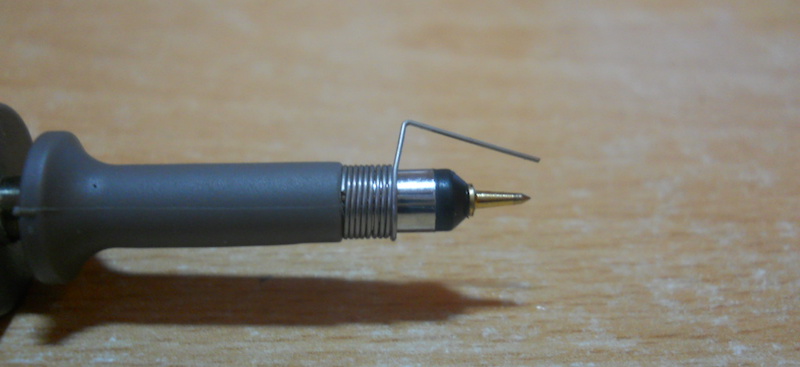
To begin, I removed the spring hook adapter from the probe, and also detached its standard ground lead (a 4 inch wire with an alligator clip). This left me with a sharp-tipped spike probe. Then I wrapped a small ground spring around the outside of the probe. This was included with my bag of oscilloscope parts, but I’d never used it before. The end result looked similar to the photo above. Now I was ready to take some new measurements.
To review, here’s another look at the scope capture from part 7, with the old bad probe grounding. This was the example where I captured signals from an unpopulated PCB, when the Yellowstone card was not installed in the computer. Yellow (Ch1) is the 5V supply voltage, measured at the 5V pin of the PCB. Notice how there are spikes of more than 1V peak-to-peak in the 5V supply.

Now here’s the same experiment again, but with the probe tip for 5V directly touching the 5V pin, and the ground spring touching an adjacent GND point a few millimeters away. The probes for the other signals were still connected in the old way.

Wow! The spikes on the 5V supply completely disappeared with this more careful measurement. But I quickly discovered that it’s very difficult to accurately position a spike probe and a ground spring in a live circuit. While taking these measurements I managed to accidentally short 5V and GND not once but twice. One of the episodes produced sparks. Yikes.
Next I reinstalled the Yellowstone card, and repeated some of my earlier measurements, but with a better ground setup. It wasn’t practical to use the spike probe and ground spring here, but I did the best I could. I hooked a short piece of wire to a ground point on the Yellowstone board, and connected the standard ground leads from all four probes to this wire. Here’s what I saw:
- Blue (Ch4) is address line A1. It’s a 5V input from the Apple II
- Purple (Ch3) is data bus D0 from the Apple II
- Yellow (Ch1) is the 3.3V supply voltage, measured at the VCC pin of the ‘245.
- Cyan (Ch2) is IOSTROBE from the Apple II, and marks the boundaries of the bus cycle.

Now I could see some supply noise again (yellow channel), but it looked fairly minor. Also some modest ringing on the data bus D0, though probably not enough to worry about. Unfortunately I still observed lots of spikes on A1 (dark blue channel). It appeared that whenever the data bus value changed (pink channel), it created spikes on A1. This was true regardless of whether Yellowstone was driving the data bus, during the low period of IOSTROBE (cyan channel), or if something else was driving the data bus, during the high period of IOSTROBE.
That degree of spikes on A1 looked concerning – possibly enough to cause a malfunction if the scope were showing a true representation of the signal. To get a better look, I needed a better ground lead for the probe. So I soldered a tiny coiled wire to the A1 pin to use as an anchor for the probe, and went back to my spike plus ground coil setup. Then I veeeery carefully applied the probe and took a measurement, without any sparks. This time I didn’t capture D0 or 3.3V, and A1 was on Yellow Ch1:

It’s harder to understand what’s happening here without the D0 trace for reference. There’s still some spiking on A1 during the bus cycle when IOSTROBE is low. This is the moment when Yellowstone’s 245 is enabled and driving the data bus. But the amplitude of the spikes during the bus cycle looks much smaller than before, only reaching about 400 mV at worst. That should probably be OK.
There’s worse spikes on A1 when its value changes, after the bus cycle ends, but I don’t think I can do anything about that since Yellowstone is inactive at this time.
Using the same probe setup, I took some other measurements of A1 (not shown) outside of Yellowstone bus cycles, during times when the data bus value changes due to something else driving the bus. I observed similar spikes of about +/- 300mV on A1 whenever the data bus changed. I’m not sure what’s causing that, but it seems to be unrelated to anything that Yellowstone is doing.
TLDNR
In short, after taking better measurements with better probe grounding, all the signals looked decently OK.
Given this, it’s probably time to try the stress test: fill all the peripheral slots with 1980s vintage cards, which should increase the bus capacitance to its maximum, which in turn should produce the highest currents through Yellowstone’s 245 bus driver chip. It shouldn’t really matter what those other cards are or what they’re doing, the only important thing is that they’re installed. If Yellowstone is ever going to fail due to high currents, ground bounce, or similar electrical problems, this should reveal it.
For this test I’ll use a new Yellowstone board with the normal chips, instead of the Frankenstein board with which I’ve been experimenting up until now, that’s been modified too many times to count. I’ll use the updated FPGA logic with pre-driving 10101010 and other changes I’ve made to help reduce peak current, but otherwise it will be identical to the board whose mysterious IIgs failures originally launched this whole glitching saga. If this test reveals any problems, I’ll look more into adding series resistors. Otherwise I’ll move on.
Read 2 comments and join the conversation2 Comments so far
Leave a reply. For customer support issues, please use the Customer Support link instead of writing comments.
I had assumed that you knew the thing about ground wire length, so I didn’t mention it. Would I be making the same mistake in assuming that you have done the square wave probe calibration?
Regardless, I think you’re there. Fingers crossed that it will work.
I actually didn’t know about the square wave probe calibration until a couple of days ago. I tried it, and three of the four probes looked pretty good, maybe just slightly out of adjustment, but the fourth was worse. Two of my probes have an adjustment screw that I used to fine-tune the calibration, but two other probes don’t have any method of adjustment that I can see. The not-so-well calibrated probe is one of these. It’s channel 3, the pink/purple channel in the scope captures that I’ve shared.