

Four Years of Yellowstone
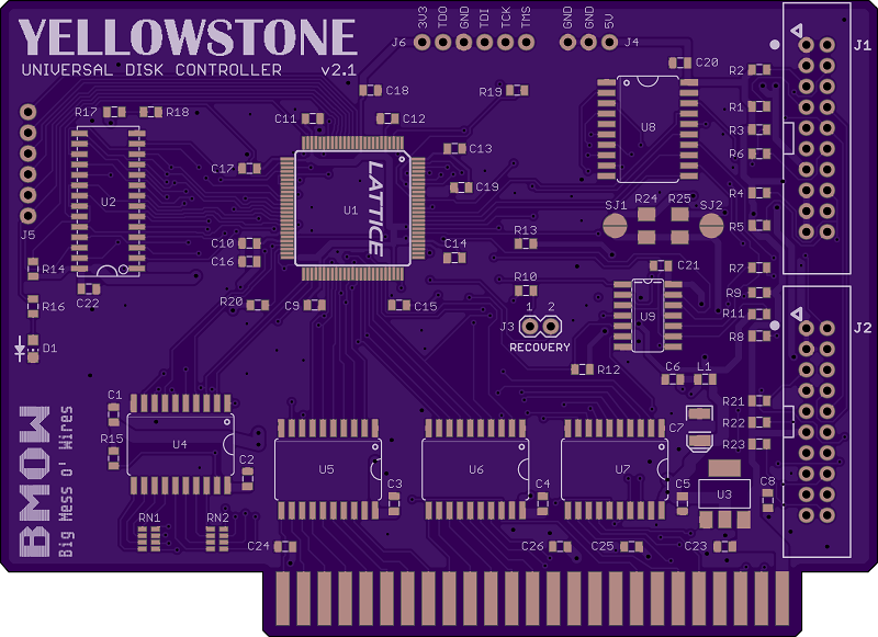
July 21, 2017 – I began the first work on what would become Yellowstone, with some attempts at designing a Verilog model of Apple’s IWM chip. Four years have passed since then, and I’m still working on this project! Today version 2.1 of the Yellowstone PCB is nearly ready for fabrication. V2.1 contains a pile of changes and improvements based on my tests of V2.0 over the past weeks. Some of the highlights:
- Added 2.2K series resistors on the -12V supply for J1 and J2, to safely limit current if a Macintosh 3.5 inch drive is connected. (bypassable with a solder jumper)
- Inserted 33 ohm series resistors on the data bus lines, to reduce ground bounce caused by fast-switching signals
- Replaced the DIP switch for selecting Disk II mode with a firmware-driven activation
- Removed the DIP switch for manually routing /ENABLE2 to J1 or J2, in favor of a firmware-driven solution
- Routed /ENABLE2 through two open-drain buffers to the two drive connectors, so a pull-down from one drive won’t make the other drive think it’s enabled
- Routed the RD and SENSE signals from each disk connector independently to the FPGA, so it can tell which drive is responding and handle error conditions when they both respond at the same time
- Added a “recovery” jumper that connects A11 through a resistor to the FPGA’s SPI /CS input, to support in-system programming of mis-programmed or blank FPGAs.
- Added decoupling capacitors on all four power supplies
- Added more ground fills, and lots more vias connecting top and bottom-side fills
- Rerouted and widened power supply traces, and repositioned bypass capacitors
- Fixed a spot where D5 overlapped a power supply trace. Oops!
- Fixed an enable signal that was connected directly to +5V instead of with a pull-up resistor. Oops again!
- Fixed the wrong supply voltage connected to one of the chips. Oops a third time!
It’s been a long journey, but everything is finally coming together. If all goes well I may have a beta-ready board in a few weeks.
Read 6 comments and join the conversation6 Comments so far
Leave a reply. For customer support issues, please use the Customer Support link instead of writing comments.
Thank you for all your hard work on this – looking forward to the final product!
https://techweb.rohm.com/knowledge/emc/s-emc/03-s-emc/7669#:~:text=One%20effective%20method%20of%20decoupling,of%20multiple%20capacitors%20for%20decoupling.&text=In%20this%20way%2C%20by%20using,noise%20can%20be%20further%20attenuated.
Noise attenuation is a important factor in card design. Using the same value as other capacitor in the mother board. Will reduce the noise attenuation. Reducing emissions.
When I was messing with video back in the day. I personally felt that having different values in the powersupply. Helped with Video vibrancy.
For example 47u,F with a .1uF. instead of the specified 47uF. But that was my experience. I forget it it was inside a vcr power supply. Or a //e. It may have been at the right length for the crystal circuit. And just acted as stabilizer for the timing.
Congratulations! And thank you for taking the time to share your troubleshooting process. It has been fun to watch the story unfold.
I should put in as well
Even though I do not have a GS or iie platinum. I would order your production version right away.
It’s getting closer to reality. The version 2.1 PCBs are here, now I just need to assemble it and test.
I’ve been following this for a while and looking forward to seeing it come to completion!