

Archive for the 'Bit Bucket' Category
Apple IIc ROM Upgrade
The more I learn about the Apple II world, the stranger it seems. Who knew the Apple IIc went through four different ROM versions, each with different capabilities, but mentioned nowhere in the model number or product label? I recently bought a IIc system, and discovered it had the oldest of these ROM versions, meaning it lacked support for external Smartport disks. Experimenting with a Smartport hard drive was the main reason I wanted the IIc, so that was a problem! After a bit of research, I did what any self-respecting hacker would do, and replaced the IIc ROM myself with a simple logic board modification. Fortunately I learned a few interesting things along the way.
Finding an Apple IIc
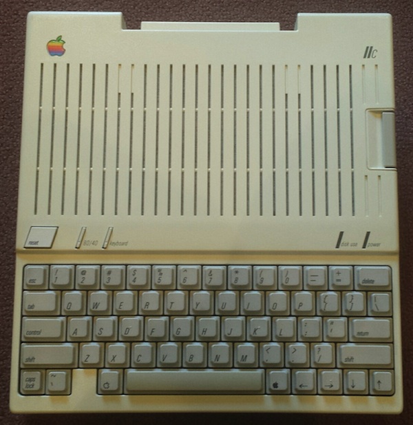
The IIc that I bought was a fairly nice one, with minimal yellowing, and the external power adapter included. If you’re searching for a IIc system on eBay, you’ll quickly notice that 80% of them don’t include the power adapter. And to make matters worse, the power adapter uses an uncommon DIN plug, so you can’t just substitute a modern laptop power supply with a standard barrel plug. What happened to all the original Apple power adapters? Did everyone carefully pack away their IIc system in the attic in 1990, but throw the power adapter in the trash? Did they all stop working? Is some guy in Kansas hoarding a stockpile of 10,000 power adapters for the Apple IIc?
Fortunately, someone in New Mexico has a large quantity of new laptop power supplies with an appropriate DIN plug for the IIc, and is selling them on eBay for $18 each. They’re probably more efficient than the original, too.
My IIc system suffered a mishap during shipping. I understand that accidents sometimes happen, but I’ve received too many vintage computers that were minimally packaged, as if expecting the post office to handle them with tender loving care. In reality these packages take a lot of abuse – imagine the box being thrown down a flight of stairs. In my case, the single layer of bubble wrap (with most bubbles popped) surrounding a 10 pound machine didn’t offer much protection. One of the corners got whacked hard, breaking the case surrounding the power switch, and leaving many small pieces rattling around inside.
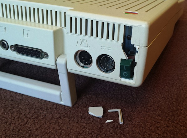
The system still worked, and I was eventually able to fish out the missing pieces. The seller gave me a partial refund for the damage, and I was able to make a rough repair with a liberal helping of super glue. Onward!
IIc ROM Versions
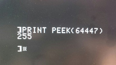
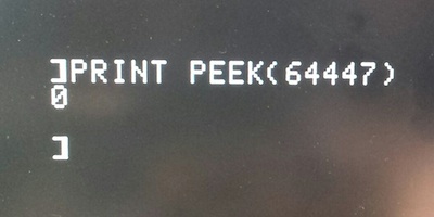
For the curious, you can type PRINT PEEK (64447) at the BASIC prompt to find what ROM version is present in an Apple IIc. There are four versions:
- 255 – The original Apple IIc ROM, size 16K. No support for Smartport disks. However, it has a nifty “PR#7” feature that allows for booting from an external floppy drive configured as drive #2, something that’s not normally possible. This was the ROM installed in my IIc. In my tests, PR#7 worked to begin booting from the external drive, but most software seemed to be hard-coded to expect to boot from drive #1. The disks would start the boot process, but then the empty drive #1 would begin seeking in vain. The only disks I found that booted successfully from drive #2 were ProDOS and the game Moon Patrol.
- 0 – With version 0, the ROM doubled in size to 32K. This ROM version eliminated the option for booting from drive #2, but added support for Smartport disks. The most common of these was the Unidisk 3.5, an intelligent external 800K floppy drive. But the Smartport protocol could also be used to communicate with other types of external disks, including hard disks up to 32MB in size.
- 3 – Version 3 accompanied a logic board change, making it possible to expand the IIc’s memory.
- 4 – Version 4 corrected some bugs present in version 3.
You can download binary images of all four versions of the Apple IIc ROM from apple2.org.za. As far as I can tell, the first 256 bytes of the ROM aren’t actually used, and attempting to read these locations on a running IIc system will modify various hardware switches instead.
ROM Upgrade
Since my IIc system lacked the memory expansion connector, there was no reason to upgrade to ROM version 3 or 4. Version 0 would give me the Smartport support I wanted, so I set that as my goal. But wait! ROM version 255 was a 16K ROM, while ROM version 0 was a 32K ROM. Obviously this wasn’t going to be a simple chip swap.
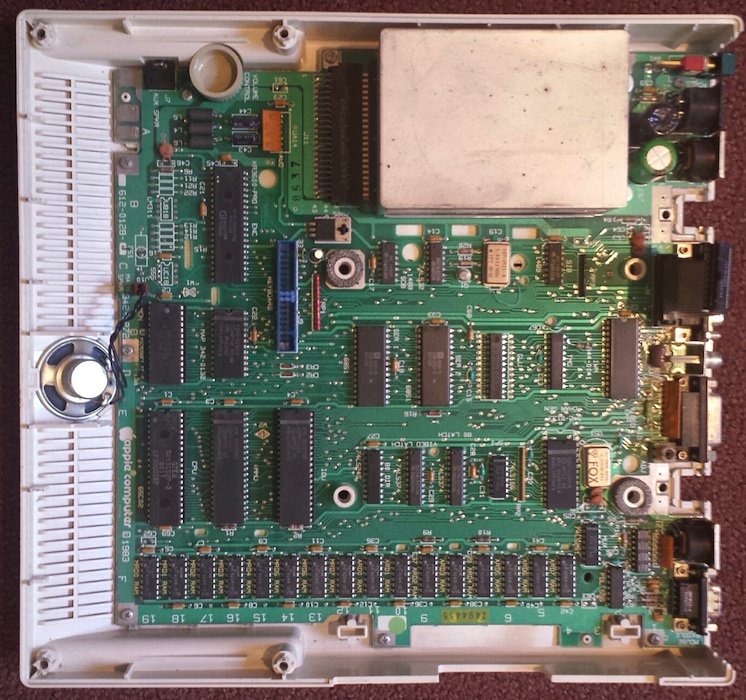
Looking at the schematics of an Apple IIc, it’s clear there’s some funny business happening with the ROM:
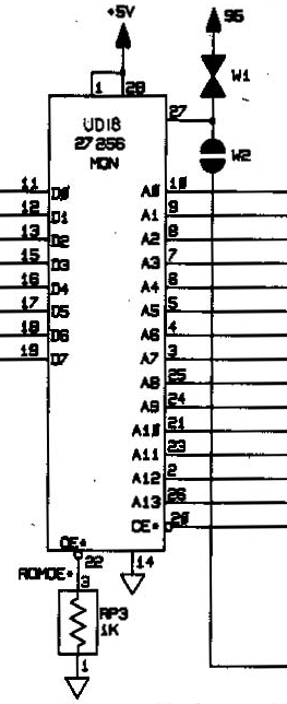
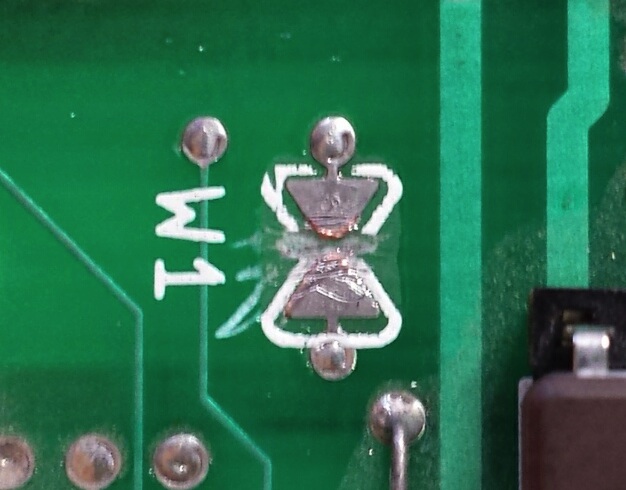
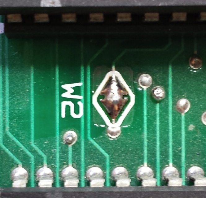
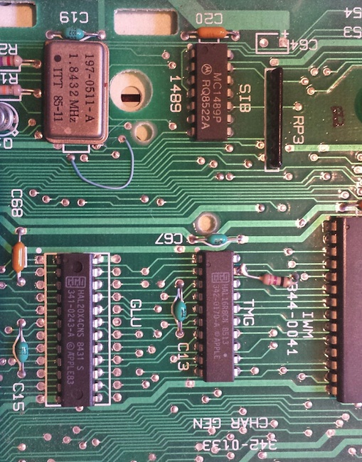
It’s labeled as a 27256, which is a 32K EPROM. But pin 27, which should be the highest address bit (A14), is instead connected to some strange components labeled W1 and W2. Huh? After a bit of poking around, it became obvious that W2 was a solder bridge jumper (normally open), while W1 was a track designed to be cut (normally closed). You can see them both here:
It looks like Apple designed the IIc from the start to support 32K ROMs, but initially shipped ROM version 255 as a 16K ROM, perhaps as a cost-saving measure. This would have allowed them to use 27128 ROMs, which hold only 16K instead of 32K. With the 27128, pin 27 is the /P or “program” pin, which must be kept high during normal operation. W1 (normally closed) connects pin 27 to the supply voltage to keep it high, while W2 is open and therefore disconnected. 16K ROM operation works.
In order to upgrade to a 27256 ROM with 32K, W1 must be cut, and W2 must be bridged. This disconnects pin 27 from the supply voltage, and connects it through W2 to the address bus, A14. Now 32K ROM operation works. It’s not the most user-friendly upgrade path, as it involves making permanent modifications to the logic board, but it’s better than nothing. You can see my cut at W1 and bridge at W2 here:
But say, where can you find a replacement ROM chip in the year 2015? Those old 27256 UV-erasable EPROMs are ancient, and I don’t own a UV eraser anyway. I looked into using a 28C256, an electrically-erasable EEPROM with an almost identical pinout, but “almost” isn’t quite enough. With some creative cutting and jumpering it could probably work, but I wanted a cleaner solution.
Jameco sells a one-time programmable 27C256 that might work. The pinout is the same, and since it can only be programmed once, there’s no need for UV erasing. But what if I made a mistake while programming the chip – I’d be left with a brick. And this particular OTP chip also has a fairly slow access time of 250ns. I wasn’t sure what speed was needed, but the RAM appeared to be 150ns, and I guessed the ROM may have the same speed requirements.
Also at Jameco is a standard UV-erasable 27C256, with a 150ns access time. This looked good, except it was labeled as a refurb product. If it were already programmed with somebody’s old data, I wouldn’t have any way to erase the chip except to leave it in the sun for a week or two, and I’m not that patient.
In the end, I bought one of each. Fortunately, the UV-erasable 27C256 proved to be already erased. After programming the version 0 image to the ROM, and making the necessary logic board mods at W1 and W2, it worked!
A Final Mystery
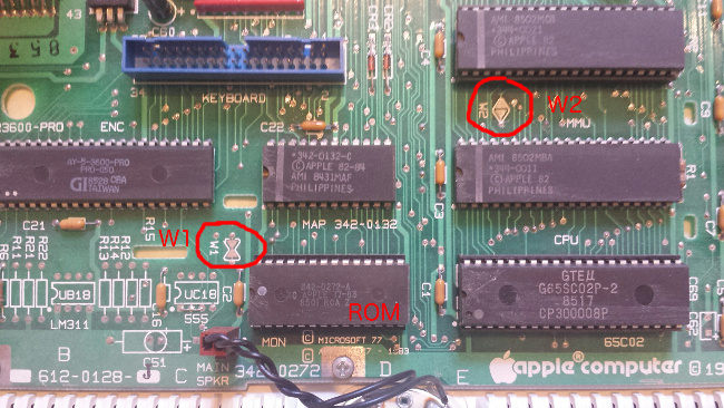
While I had the logic board exposed, I noticed a few mysterious modifications already present. Just next to the 1.8432 MHz oscillator, a narrow purple wire connected two vias. And nearby, a resistor connected pin 19 of the TMG chip to another via. The purple wire looked very cleanly done, but the resistor was much uglier. Were these older repairs from another hobbyist, or perhaps factory changes made by Apple for some earlier logic board revisions? What are these changes for?
Anatomy of a Product Failure

Recently I launched the Sonic Bow Tie – the first project I’ve ever designed from the start to be a product, instead of a project that turned into a product by accident. The Bow Tie is an electronic kit with a circuit board shaped and sized like a real bow tie. It’s a blinking, beeping, musical tuneable theremin-type thing you can actually wear – perfect for those nerd-centric formal occasions, or project night at the local hacker space. Following the examples of the Weevil Eye, the Simon, the Drawdio, and basically everything at ThinkGeek, it’s intended to be a fun project kit to assemble with a friend, appealing to engineers with a sense of humor. I mean who wouldn’t want a dazzling neck-based audio-visual spectacle?
Unfortunately, the rest of the world doesn’t seem to agree that bow ties plus electronics is a match made in heaven. Since I launched the Sonic Bow Tie about ten days ago, it’s received zero feedback, zero interest, zero sales, zero anything. It’s enough to make me wonder – did I actually hit the “publish” button on that product announcement? Yup, I did.
This isn’t the end of the world, and my financial investment in bow tie kits is small. But what disturbs me is that something I thought would be fairly popular, or at least fairly amusing, proved to be such a complete flop. I spent many hours iterating on the circuit design and physical layout, sourcing parts, and manufacturing kits for an idea that proved to be a total non-starter. It shows that using yourself and your immediately family as a proxy for public opinion may not be the smartest idea. Meanwhile, if I don’t find more bow tie enthusiasts, I’ll be buying space in a New Mexico landfill next to all those unsold Apple Lisas and E.T. cartridges. Live and learn!
Do you have any good product failure stories you’re willing to share? Post ’em here and make me feel better. 🙂
Read 9 comments and join the conversationThe Sonic Bow Tie


The Sonic Bow Tie is an electronic kit for engineering geeks with a sense of humor, available now at the BMOW store. The circuit board is shaped and sized like a real bow tie, and is colored classic black. Once assembled, a piece of ribbon can be anchored through the board’s central mounting holes, making it easy to wear at the collar of a dress shirt or tied around a ponytail.
Wearable computing is the latest trend, and you’re at a party listening to some hipster brag about his new iWatch. “Hmm, not bad…” you say. Then you casually reach for your collar and switch on your SONIC BOW TIE 3000. Wham! Your audience is blown away by your neck-based audio-visual spectacle. Lights flash and a digital melody bursts forth. With a wave of your hand you exert theremin-like controls, shifting the pitch of digital warbling at will. The onlookers cry out “WHAT IS THIS SORCERY?!”
Attending a wedding soon? Graduation ceremony? Audience with the pope? The Sonic Bow Tie 3000 is the perfect geek accessory for any formal occasion.
Ladies: are bow ties not your style? Turn it around, and make a dazzling electronic ponytail holder perfect for your next Maker Faire presentation or inaugural ball.
While a pair of jumbo 10 mm LEDs flash, the bow tie repeats a simple 8-note digital melody, alternately soothing and annoying those around you. A center mounted photo-resistor acts as a light sensor, biasing the melody’s pitch. Turn your body towards the light, and the pitch shifts upward. Turn away or shade the sensor with your hand, and the pitch shifts downward. Fortunately there’s also an on/off switch, for when your friends threaten you with bodily harm if they hear one more second of that #*&($#@!
The kit contents are simple through-hole parts, so it’s easy to solder even for a beginner. Build one for yourself, or get a kit for your kid/student/friend and assemble it together. Who wants the boring LED blinker in a typical learn-to-solder kit, when you could have a crazy bleeping sonic bow tie theremin?
How it Works

The fun begins with a classic 555 timer, configured in astable mode to generate a square wave with a frequency around 1000 Hz. This is IC1A as shown in the circuit diagram. The exact frequency of the square wave is determined by the values of C3 and R1. R1 is a photo-resistor whose resistance varies with illumination. This causes the timer frequency to shift up or down in response to changing light conditions. When connected to a speaker, it creates a continuous tone whose pitch changes depending on the light.
A continuous tone isn’t very interesting, but we’re not done yet. A second 555 timer is also configured in astable mode, generating a square wave at about 4 Hz (250 millisecond period). This is IC1B in the circuit diagram. A pair of LEDs are connected to this square wave output, causing them to blink 4 times per second.
The 4 Hz signal is also used as the clock input to IC2A, a 4-bit binary counter. The circuit uses a CMOS CD4520 binary counter chip, instead of a more common 7400 series binary counter, because the CD4520 can tolerate supply voltages up to 20 V. This makes it possible to run the entire circuit directly off a 9 V battery, with no voltage regulator.
The lowest three bits of the current count are connected through series and parallel resistors to the control voltage input of the first 555 timer. This biases the continuous tone up or down in pitch, with a new bias voltage appearing every 250 milliseconds when the counter advances. The result is a repeating melody of eight notes, whose relative pitches are set by the binary counter, and whose overall pitch can be shifted further up or down by changing illumination at the photo-resistor.
Wear and Usage
To wear the Sonic Bow Tie 3000 around your neck, drop the battery inside your front shirt collar and allow it to hang loose by the clip wires. Normally this is all that’s needed to anchor the bow tie at your collar. If desired, a ribbon or shoelace can be passed through the two holes in the center of the circuit board, and tied around your neck.
To wear the bow tie as a ponytail holder, pass a ribbon through the center holes, and tie it around your hair at the base of your skull. The battery can be dropped inside the rear of your shirt collar, or hidden inside your hair.
The pitch bends of the digital melody are controlled by the level of illumination on a photo-sensor mounted at the tie’s “knot”. The bow tie works best indoors, in a room with moderate lighting. To shift the melody’s pitch higher, move closer to a light source, or turn the bow tie to face directly towards the light. To shift the melody’s pitch lower, move away from the light source, or shade the photo-sensor with your hand. By waving your hand rapidly above the photo-sensor, a warbling vibrato effect can be achieved. Is it science, or sorcery?
Read 1 comment and join the conversationSorry Pakistan (Why PayPal Stinks)

I use PayPal to accept payment for all BMOW products. Customers can create a PayPal account and send money from their account balance, or they can use PayPal with a Visa credit card to send payment directly without creating an account. That’s mostly worked OK, but today I learned that PayPal straight-up denies all credit cards from Pakistan, no exceptions. It’s like a giant middle finger, extended to an entire country of 182 million people. In fact there are 18 countries where PayPal won’t accept payments, some of which would probably never be customers of mine anyway (Papua New Guinea?), but with over 100 million people and English as an official language, the absence of Pakistan is especially galling.
PayPal is popular, at least in the United States, and it’s convenient, but it can also be infuriating. They act like a bank, and hold balances and perform money transfers like a bank, but aren’t subject to the same regulations as a bank. The internet is full of horror stories where PayPal froze accounts containing thousands of dollars due to “suspicious activity”, with no path or process for people to appeal or even discuss it with a human being. And from a seller’s point of view, the PayPal dispute resolution process is as bad as it gets. If you want to scam me, just buy a Floppy Emu, and when it arrives file a PayPal dispute saying that the item was not as described. You will get your money refunded 100% of the time and end up with free hardware, and there’s nothing I can do about it. (Please don’t actually do this.)
Unfortunately there are no realistic alternatives to PayPal that provide similar capabilities. WePay is US-only. Square is only slowly expanding outside the US. Amazon Payments is a mess. Too many companies seem to believe the world consists of the United States and “miscellaneous other”, a group of 6.7 billion people who are somehow not very important.
After some investigation, it looks like the best solution for a one-time payment from Pakistan to the United States is a money transfer service like Western Union or MoneyGram, even though they charge a 10% commission. It’s OK for a one-off, but if I were receiving a lot of orders from Pakistan, it would be a poor long-term solution. If anyone has experience with sending money from Pakistan to the USA and can suggest a better method, I’d be happy to hear about it.
Read 8 comments and join the conversationOverheating a Voltage Regulator
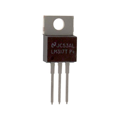
How much current can a typical linear voltage regulator provide, like an LM317? The datasheet says 1.5 amps, which should be plenty for most hobbyist breadboard projects – or so I thought. Years ago I bought a little LM317-based power supply with breadboard-friendly headers, and it’s been great, except for an occasional tendency to randomly turn off when I’m using “too much power”. I never stopped to investigate further or measure how much current is too much, until now.
I’ve got a decent little 68008-based computer experiment working on a breadboard now (more details soon), and it runs indefinitely with the LM317 supply. But when I added an Arduino Pro Mini to the breadboard, the power supply always shut off within 30 seconds, even when none of the Arduino I/Os were connected to anything! What the heck? I measured the 68008 system’s current draw at about 250 mA, and the system plus Arduino at 280 mA. That seems low enough – far less than 1.5A.
Oh right, power dissipation! My wall-wart supplies 12V, which is regulated to 5V by the LM317. A 7 volt drop times 280 mA equals almost 2 Watts dissipated as heat. I do have a heat sink on there, but it’s just one of those little 1-square-inch folded metal pieces. How many watts can those safely dissipate? I found some info that estimated their thermal resistance at 21 degrees C per watt, so at 2 watts it should rise to 42 degrees C above ambient temperature: roughly 63 C. That pretty hot, but not insanely hot. I would have expected the LM317 to continue working at that temperature.
I removed the Arduino, and added some more random LEDs to increase the current draw to 350 mA, just to be sure there wasn’t something specific about the Arduino that was causing the problem. Then I tested out several different sizes and configurations of heat sinks. No matter what the heat sink, the LM317 shut down after about 35 seconds from starting from cold. It was bizarrely reliable, and bigger heat sinks didn’t seem to make a difference. If the LM317 was already warm, it would shut down after as little as 3-5 seconds. I just now discovered that I’ve been installing the heat sinks backwards – I had the fins facing out instead of in. But I don’t think that could explain it.
I can switch to a 9V wall-wart, or some different type of regulator, so this isn’t a major problem. But I’m curious – is this normal? I feel as though I must be overlooking something, and the LM317 shouldn’t be shutting down at these relatively low current levels.
Read 7 comments and join the conversationRaspberry Pi 3D Performance Demo
I’ve recently gotten interested in 3D programming for the Raspberry Pi. I’m not sure why RPi 3D development interests me when desktop 3D mostly doesn’t – I guess there’s just something fun about coaxing as much 3D performance as possible from a little $35 device. Armed with 15-year-old Open GL experience and only slightly newer video game console dev experience, I set out to push the limits of the Raspberry Pi’s 3D hardware.
Finding the Right Yardstick
The first question I faced was how to best measure 3D performance. Does 60 FPS rendering of a single cube represent better performance than 10 FPS rendering of a complex scene? What should I measure, exactly? After mulling on the problem for a day, I decided the only decent metric I could measure was triangles per second. A cube is made of 12 triangles, and at 60 FPS that’s 720 triangles per second. A complex scene might consist of 100,000 triangles, and at 10 FPS that’s 1 million triangles per second.
Many 3D programmers argue that triangles/second is a useless metric, fundamentally flawed in its conception, because it ignores the fact that some triangles are much more expensive to draw than others. A large triangle is more expensive than a small one. A triangle with lots of textures and complex lighting shaders applied to it is more expensive than a solid blue triangle. Triangles whose outside faces are oriented away from the viewer, or that lie behind other previously-drawn triangles, are almost free. Increasing the screen resolution makes all triangles more expensive. There are so many factors that affect the cost of rendering a triangle, that comparing triangles per second benchmarks between different hardware platforms or different programs is virtually meaningless.
In the context of the same program drawing the same triangles on the same hardware, however, triangles per second is still a useful measure of relative performance. If a change to the program can increase triangles/second without sacrificing image quality somehow, then it’s a win. In fact, unless the API can access specialized hardware performance counters in the graphics processor itself, triangles/second and frames/second are virtually the only things it’s even possible to measure.
Building the Program
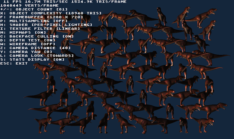
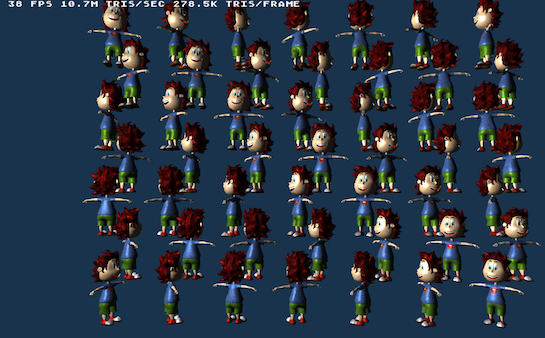
Over the course of a few evenings, I put together a demo program called rasperf3d, which you can download from the BMOW web site. My twin goals were to create an OpenGL ES sample program more complex than Raspberry Pi’s hello_triangle example, and to make a tool to measure the impact of screen resolution, model complexity, shader type, and other rendering settings on frame rate. The program draws many copies of the same model in a grid layout on the screen, and shows real-time rendering performance data including a measure of triangles per second. I can use the keyboard to change the current rendering settings, and see how it affects overall 3D performance.
For Raspberry Pi Programmers
The source code compiles on a stock install of Raspbian Wheezy, with no extra libraries needed. X Windows is not required nor used.
Some of the more interesting things demonstrated in the code are:
- Basic vertex and fragment shaders for Phong (per-pixel lighting) and Gouraud (per-vertex lighting)
- Using ETC1 compressed textures
- Rendering with vertex buffer objects
- Drawing text with a bitmap font
- Dynamically changing the screen resolution
- Dynamically enabling multi-sampling
- Taking a screen shot
Performance Measurement
Press S to hide all but the first row of text – this improves performance slightly. Use the keyboard to modify these settings:
- Number of objects rendered. Each object is 1 draw call.
- Type of object: Five choices, from a 12 triangle cube, to a 55K triangle robot.
- Screen resolution. From 1920 x 1080 down to 568 x 320.
- 4x Multi-sampling: on/off.
- Shader: textured with per-pixel lighting, textured with per-vertex lighting, untextured with per-pixel lighting, untextured with per-vertex lighting, flat colored.
- Texture filter: linear or nearest.
- Mipmaps: on/off.
- Backface culling: on/off.
- Depth test: on/off.
- Wireframe view: on/off.
- Camera distance away from the “wall of objects”.
- Camera yaw angle – view the wall of objects at an oblique angle, or edge-on.
- Camera look away – rotate the camera 180 degrees, so that all triangles will get clipped out.
- Secret feature: press R to take a screenshot.
For the curious: All the object models use one 256×256 compressed texture with mipmaps, and the same shader with one directional light, so the only performance difference between them is due to their geometry. All models have indexed verts. Each vertex has position XYZ, normal XYZ, and texture UV stored as 4-byte floats, for a total of 32 bytes per vertex. Rendering is done with VBOs (vertex buffer objects) and glDrawElements. Each copy of the model is a separate draw call to OpenGL.
Conclusions
I was able to push the hardware as high as 16 million triangles per second, while rendering a dozen copies of a 19K triangle dinosaur model. This was on a stock Raspberry Pi, at a screen resolution of 1280 x 720, and with the texture and lighting settings mentioned above. Higher numbers are possible, but require using rendering settings that aren’t very realistic for a “real” 3D program. Absolute peak throughput was 27.3 million tris/sec with a very simple flat-colored shader, screen resolution of 568 x 320, and the camera pointed away from the objects so that all triangles were clipped.
19K triangle object models are probably heavier than any real Raspberry Pi 3D game would use, since the hardware is only able to draw about a dozen of them before the frame rate dips below 60 FPS. Using a more appropriate model – a 500 triangle frog – the hardware was able to reach just 4 million triangles/second, but could draw 132 frogs before the frame rate fell below 60.
How does this compare to my PC or smartphone or Playstation? As mentioned earlier, direct comparison of triangle per second numbers between hardware platforms is generally meaningless. If I could run rasperf3d on a desktop PC or the Playstation 4, we might get a better relative comparison, but even that would be questionable. The program wasn’t designed to be a general purpose cross-platform 3D benchmark.
So I can’t put any specific numbers on it, but I feel comfortable in saying the comparison to modern 3D hardware is not favorable. That’s fine – that’s to be expected on a $35 computer the size of credit card. It’s been a very long time since I did any real professional 3D development work, but my recollection is the Gamecube, Xbox, and Playstation 2 games I worked on had scenes similar to my frog test. A typical scene in one of those games might have had something on the order of 100 objects, each of which consisted of a few hundred triangles, and used fairly basic textures and lighting. It looks like the Raspberry Pi should be capable of roughly the same.
Read more on this topic in the Raspberry Pi forums, here and here.
Read 1 comment and join the conversation