Archive for the 'Bit Bucket' Category
Entry-Level Oscilloscopes
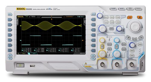
It’s time to shop for a new oscilloscope. My trusty HP1631d has served me well, but it’s almost 30 years old, and it’s not even really an oscilloscope but a logic analyzer. This boat anchor is big, heavy, loud, cumbersome, and feature-starved. I’ll probably still keep it around for the logic analyzer functions, but for traditional oscilloscope work I’d like something more modern.
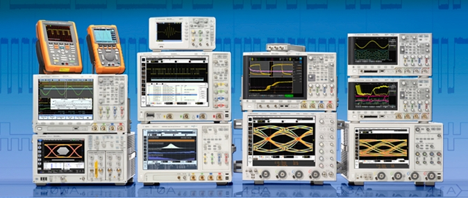
Fortunately, this is a great time to be a hobbyist looking for a low-cost scope. There’s practically a tidal wave of entry-level digital scopes coming out of China today, with plenty of good options in the $300-$400 range. The only problem is there are so many options, it can be hard to sift through the blizzard of information and specs in order to choose one!
Why a new entry-level scope, instead of a used digital or analog scope from somebody like Tektronix, which might be purchased for the same price or less? There are some great values on eBay and Craigslist for sure, and for someone on a minimal budget, I think an older used scope is the best option for getting started in electronics. But the major drawback of all those used scopes is that they’re invariably big, heavy, loud boat anchors. They also lack modern connectivity options like USB. I’ve already got a boat anchor, thank you.
When shopping for a scope, there are three primary specs that get the most attention: bandwidth, sample rate, and memory depth. I had only a hazy understanding of how these were related until I began studying a few days ago.
Bandwidth
Bandwidth determines the fastest signal you can measure with the scope. It’s determined by the scope’s front-end electronics, as well as by the probes you’re using. But does that mean a 50 MHz scope is good for measuring signals up to 50 MHz, and useless for anything beyond that? No. The definition of bandwidth for oscilloscopes is actually very specific: it’s the frequency at which the measured amplitude of the input signal is decreased by -3dB (about 30%) of its original value. If you view a 50 MHz sine wave that’s 1v peak-to-peak on a 50 MHz scope, the scope will show 0.7v peak-to-peak. You can view signals faster than 50 MHz on the scope, but they’ll be attenuated even more than -3db. Signals slower than 50 MHz will be attenuated too, but by less than -3db. There’s no magic cutoff at 50 MHz where the scope just stops working.
Sometimes you’ll also see a scope’s rise time advertised. This is the time the scope requires to move from 10% to 90% of a new voltage input. By doing some math, you can demonstrate that bandwidth in GHz is approximately 0.35 / rise time in nanoseconds. So a scope with a 7 ns rise time should have a bandwidth of 0.35 / 7 = 0.05 GHz = 50 MHz.
OK, a little attenuation doesn’t sound so bad. But typically you won’t be measuring sine waves, you’ll be measuring things like square waves. You probably know that square waves are composed of an infinite series of sine waves at odd harmonics of the fundamental frequency. A 40 MHz square wave can be thought of as a 40 MHz sine wave, plus 1/3 of a 120 MHz sine wave, plus 1/5 of a 200 MHz sine wave, plus 1/7 of a 280 MHz sine wave, etc.
If you view that 40 MHz square wave on a 50 MHz scope, it can see the 40 MHz fundamental sine wave, but all the harmonics are above its bandwidth, and are attenuated into insignificance. The result is that the 40 MHz square wave looks like a 40 MHz sine wave when viewed on the 50 MHz scope. That’s really bad. If all you care about is knowing the signal’s frequency, then I guess it’s OK, but the actual shape of the signal is completely lost. If you want to measure the signal’s rise time or duty cycle, you just can’t do it on that scope.
This explains why you need a scope whose bandwidth isn’t just strictly higher than the frequency of the fastest signal you’ll be measuring, but much higher. How much? A common rule of thumb is 4x-5x higher. At 5x, the first two harmonics of the square wave will fall within the scope’s bandwidth, so that seems like a good place to draw the line. But really I think this is one of those “it depends” situations. If almost all the work you do is at 10 MHz or below, but you occasionally have some elements that run as fast as 30 MHz, then you’ll probably be fine with a 50 MHz scope. It just means that when you do need to examine a 30 MHz signal, it will be as if looking through a clouded glass, where the true shape and amplitude of the signal are partly obscured. If you just need to know whether there’s any signal at all, or what its frequency is, then that’s fine. But if you need to look for small glitches or timing problems at 30 MHz, it may not be.
Sampling Rate
All modern oscilloscopes are digital, and sample the input signals millions or billions of times per second. But how fast does the sampling rate need to be, and what’s its relationship to the bandwidth? When I first began looking into it, I thought sampling rate only needed to be 2x bandwidth (Nyquist). While that’s enough to reconstruct the input signal’s frequency, it won’t tell you anything about its shape. At 2x, you’ll get one sample during the high part of each period, and one sample during the low, but you’ll have no idea if the signal is a sine or a square or a lumpy shape. The common rule of thumb is that the sampling rate should be 4x-5x the bandwidth. So if you typically need to examine 20 MHz signals, you should look for a scope with 100 MHz bandwidth and 500M samples/sec.
On most scopes, the sampling rate is cut in half when using two channels instead of one.
Memory
All those digital samples have to be stored somewhere. With more memory, the scope can store more of them. The obvious result of having more memory is that the scope can capture a longer time duration in a single acquisition, which can be useful if you need to debug something like a lengthy serial communication. Or it can store more samples during the same time duration, making it possible to zoom in on the acquired waveform to examine small details.
Not all oscilloscope memory is created equal. Many scopes have standard memory and “long memory”, which operate at different speeds. The long memory stores more samples, but can’t store them as fast as standard memory, so the sampling rate must be reduced when long memory is used. Other scopes have long memory that operates at full speed. This is an important consideration that’s generally not mentioned anywhere in the scope’s advertised specs, but must be inferred from careful reading of the manual or datasheet.
Bandwidth + Sampling Rate + Memory = Confusion
It’s important to recognize that a scope’s advertised sampling rate is its maximum sampling rate, but the actual sampling rate may be much lower. As described above, the use of two channels or slower “long memory” are some reasons that the sampling rate may be reduced below the maximum. But the main reason is that the rate must be reduced when the capture duration increases, in order to keep the total number of sample points small enough to fit in memory. For example, if you want a 50 microsecond per division timescale, that’s a 500 microsecond capture duration. If your scope has 10K points memory, you can only sample the signal at 10000 / 500 us = 20M samples/sec, regardless of how fast the scope’s maximum sample rate is.
When the scope’s sample rate is reduced, its effective bandwidth is also reduced. At 20M samples/sec, the scope has no hope of capturing signals faster than 10 MHz, and won’t be able to faithfully capture the shape of signals faster than about 2 or 2.5 MHz. This leads to the conclusion that memory size constrains bandwidth. That may be old news to some, or a total surprise, as it was for me. With a small memory, at longer timescales, a fancy 200 MHz scope may essentially turn into a 10 MHz scope.
Examples in the Real World
Take a look at this table, which I found on an oscilloscope forum. It compares two popular entry-level oscilloscopes with 100 MHz bandwidth and 1Gs/sec sample rate: the Rigol DS1102e, and the Owon SDS7102. The specs are the same, so you might expect they would have the same basic capabilities for signal capture, but that’s not true. The Owon has 10M points memory per channel, while the Rigol has 1M points shared between both channels. The Owon memory also runs at full speed, while the Rigol’s long memory runs at half speed. The red line shows the point as which the effective bandwidth is reduced below 100 MHz.
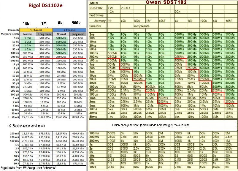
The result of 20x more memory and 2x faster memory is a big performance advantage for the Owon. In dual channel mode using the full memory capacity, the Owon can do 500Ms/sec while the Rigol can only do 250Ms/sec. At longer timescales, the difference grows larger. At 1ms/division, the Owon can still do 500Ms/sec while the Rigol is slowed to only 20Ms/sec – a 25x difference! You would never know this if you only looked at the advertised bandwidth and sample rate figures from the manufacturers.
Does this mean the Owon is a 25x better scope than the Rigol? Definitely not. For one thing, most reviewers seem to feel the Owon’s UI design is somewhat clunky and confusing compared to the Rigol. But even looking just at measurement capabilities, you could definitely argue that capturing at 1ms/division while retaining 100MHz bandwidth isn’t very useful in the real world. Most of the time, if you want to examine high speed signals in the greatest detail, you’ll capture them with a short timescale like 50ns, where the sample rate difference between the two scopes is only 2x. And if you’re just looking at a single edge or small number of signal periods, then you won’t need the Rigol’s long memory, and there won’t be any sample rate difference at all.
Bandwidth Hacking
One wrinkle that complicates the shopping process is that some scopes from Rigol and Hantek can be “hacked” in software to unlock higher bandwidths. I first read about these hacks a couple of years ago, but thought they were bullshit. Sure, you might unlock the menu options for higher bandwidths, but if the scope’s ADC and other front-end components only had 60 MHz bandwidth, there’s no way a software change could magically make it into a 200 MHz scope. But after doing much more research, it seems that all scopes in Rigol’s DS1000 line and Hantek’s DSO5000 line are actually 200 MHz scopes, with some models crippled in firmware to limit their bandwidth. People smarter than me have done bandwidth measurements on the hacked scopes, and even disassembled 200 MHz and 60 MHz scopes from the same family. They proved that the internal electronics are the same, and a 60 MHz scope hacked to 200 MHz really does have 200 MHz bandwidth.
Assuming such hacks really work, are they ethical? Are they like pirating software (which I don’t), or more like unlocking your CPU multiplier so you can overclock it (which I do)? Or like jailbreaking your iPhone? My moral compass doesn’t have any problem with it, but I’ll reserve the right to change my mind.
The Contenders
After staring at various oscilloscopes until I was blurry-eyed, I’ve narrowed the list of contenders to just a few.
Rigol DS1052e / DS1102e – This scope has been around for several years now, and has a pretty good reputation. The 50 MHz version can be had for about $300, and can be hacked to 100 MHz. I even used one of these at work for a while. But the DS1000 line is getting a bit old and crufty, with a smaller screen and fewer features than some of the newer competition. I’ve more-or-less ruled it out.
Owon SDS7102 – The Owon has the largest, fastest memory of any entry-level scope today, with 10M points per channel full-speed memory. It also has a very nice 800 x 600 8″ display. It can be purchased for about $420 including shipping, and reviewers on Amazon.com give it an average rating of 4.5 stars. I was very excited about this scope initially, but reviews on electronics web sites haven’t been as enthusiastic as Amazon’s. Many people complain about the user controls being somewhat clunky and confusing. It sounds like the interface isn’t terrible, just kind of annoying. Is it worth being annoyed by your scope every time you use it, in exchange for better sample rates or longer captures in the rare cases when you need them? Probably not.
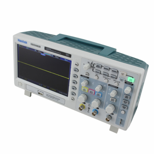
Hantek DSO5102B – This same 100 MHz scope is also sold under several other brand names and model numbers. There’s an epic 2000 post discussion thread about this scope on the EEVblog forums, describing how to hack it to 200 MHz, modify the interface screens, and tweak other features. Even unmodified, it seems to be a fairly popular and easy to use scope, with most people scoring it best among the entry-level scopes for user interface and features. It’s about $370 including shipping. This is my leading choice at the moment. I was almost ready to buy it before I watched Dave Jones’ video review of it on EEVBlog, where he initially seemed quite pleased with it before he ran into some problems, and finally gave it a thumbs down.
Hantek DSO5062B – This is the 60 MHz version of the Hantek line, and sells for about $345 shipped – $25 less than the 100 MHz model. Both can be hacked to 200 MHz. 100 MHz is really plenty for me, so is it worth $25 to avoid the hassle of hacking the 60 MHz version, and any possible problems it might cause? Yeah, I think it is, so the DSO5062B is probably out of the running.
Hantek DSO5102P – This is the 100 MHz model, but without long memory. It’s $320 shipped, or $50 less. How useful is that long memory, really? There’s no question it could be useful in some situations, but most of the time I’m guessing I wouldn’t use the long memory at all. Why pay for a feature you’re not going to use? Saving $50 sounds good, but when I run into a situation where the long memory would have been useful, I’ll probably wish I hadn’t been so cheap.
Hantek DSO5072P – This scope is 70 MHz, without long memory, but otherwise the same as the other Hanteks. It too can be hacked to 200 MHz, and it’s only $270 shipped. That’s $100 cheaper than the DSO5102B. For $100, would I go through the headache of hacking the scope, and give up the long memory? Hmmm, maybe.
Rigol DS2072 – This last scope is really in a different class than all the others. The major specs are about the same, but the build quality, features, and overall polish are much higher than the others. Dave Jones made an EEVBlog review where he positively gushed about this scope. The only problem is that it’s $840, and that’s for the 70 MHz version! The 100 MHz version is a smooth $1143. But like the other Rigols, the 70 MHz model can be hacked to 200 MHz.
What do you get for $840 vs $350 or so for the other scopes? For starters, the sample rate is 2Gs/sec, as opposed to 1Gs/sec on all the other scopes I mentioned. Long memory is 14 million points, expandable to 56 million. Jitter, noise floor, and all those other details are much better than with the other scopes. It’s a so-called DPO (digital phosphor oscilloscope), where many copies of a periodic waveform are overlaid onscreen with an intensity gradient that’s similar to an analog scope display. Its waveform refresh rate is extremely high, at around 40,000 waves/second, making it great for catching rare glitches. It always runs the sampler at the maximum sample rate, doing averaging on-the-fly when necessary to keep the number of stored samples small enough to fit in memory. It has some very, very cool waveform analysis features. And it even has some basic logic analyzer functions, like automatic decoding of SPI and I2C traffic.
If Santa Claus were bringing me a free oscilloscope, I’d ask for the Rigol DS2072. But if I’m paying out of my own pocket, I’m not convinced all those nice features justify a 2.5x price difference. At the end of the day, I’ll still be looking at the same basic signal on either scope. Bells and whistles are great, but maybe not 2.5x great.
Your Toyota vs. my Horse
Shopping for a new entry-level scope to replace my HP1631d has been funny at times. Even the worst of the contenders are still miles ahead of the 1631d in most respects. It’s amusing to read complaints about scopes that “only” refresh 40 waveforms/sec, when my current scope can barely manage 2 waveforms/sec. Or to read discussions about whether the Hantek –P models are hamstrung by having “only” 40K points of sample memory, when my current scope has just 1K points. 1K!
Read 22 comments and join the conversation
Inside Vintage Electronic Toys – How Speak & Spell Works
The 1970s were a great time to be a geeky kid, thanks to the introduction of the first digital electronic toys. With their beeping songs and blinking lights, who could resist them? Recently I decided to take a trip down memory lane, buying some classic 70s digital toys, and carefully disassembling them to reveal their vintage electronic guts. For about $50 and some time spent on eBay, I found myself the proud new owner of a Little Professor calculator, a Mattel Electronic Football handheld game, and the gem of the collection: a Speak & Spell talking toy.
Batteries
Today most portable electronics use a couple of AA or AAA batteries, but not these vintage devices. Little Professor and Football both need a 9V battery, and Speak & Spell actually uses four C cells. C cells?? I don’t think I’ve ever seen those used anywhere except flashlights and things with motors. The designers must have anticipated some major current demands that would have exhausted 9V or AA batteries too quickly.
The popularity of 9V batteries may have been because older semiconductor technologies often required higher voltages, like 9V or higher, compared to today’s chips that run at 5V, 3.3V, or even less. It’s also possible that classic devices relied on linear regulators to bring 9V down to the required 5V, but modern devices typically use boost regulators to bring 1.5V or 3V up to their required voltage.
Display
Another shared feature that caught my attention was the displays. None of the toys has an LCD display, and certainly not an LED display. In the mid-to-late 70s when these toys were made, LCDs were high tech and out of reach for cheap consumer devices. Instead of an LCD, Little Professor and Football both have red matrix LED displays, and Speak & Spell has a blue vacuum-fluorescent display that looks like something out of a sci-fi movie. Very retro!
Little Professor – Texas Instruments (1976)
The oldest of the bunch is Little Professor, first released by Texas Instruments in 1976. Over the years it went through many revisions, with different displays and buttons. The original version is shown here.
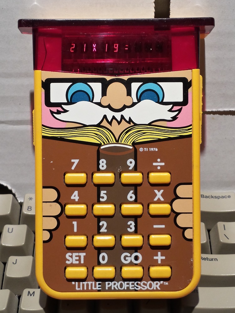
Little Professor is essentially a calculator in reverse: the display presents a math problem, such as 21 x 19, and the player must enter the answer. If the answer is correct, a new math problem is presented. An incorrect answer flashes EEE on the display. There are no sound effects, and no feedback of any kind beyond the numeric display. It’s drill-and-practice at its dullest, yet TI managed to sell over 1 million units in 1977.
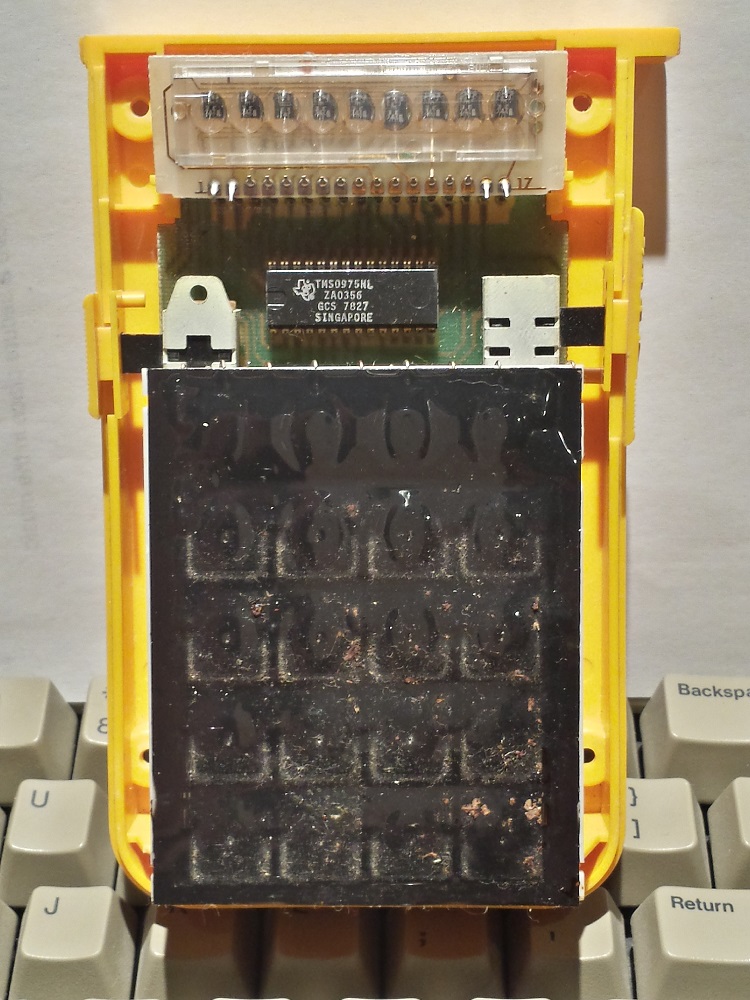
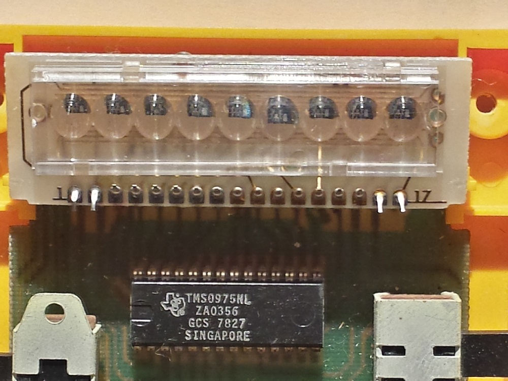
Peeking inside reveals very few parts, and the contents are mostly empty air. There’s a membrane keyboard, LED matrix display, two slide switches for on/off and difficulty selection, and a single 28-pin SDIP (shrunken dip). That’s it. There’s not a single resistor or other passive component anywhere.
The secret to the low part count is that chip: a TMS0975 microcontroller. It’s a member of TI’s TMS1000 family, and a sibling of the TMS0972. These microcontrollers were widely used in other “real” calculators of the same period. They were 4 bit architectures, with three data registers, 1KB of ROM, and 32 bytes of RAM. The nominal clock speed was only 400 kHz. Unlike today’s microcontrollers, the ROM store was not re-writable, so once a program was stored in the MCU it was fixed forever.
Beyond the microcontroller functions, the TMS0975 also incorporated the LED digit drivers, keypad input, clock oscillator, and other elements. No external passive components were required. This would have helped keep manufacturing costs low. TI probably made a nice profit selling these at $20 apiece – that’s $82 in 2013 dollars!
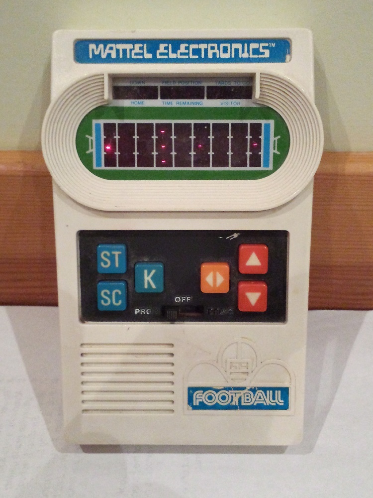
Mattel Electronic Football – Mattel (1977)
Electronic Football was one of the first releases in Mattel’s long-running handheld sports series. And to be clear, we’re talking about American football here, not soccer. Two players take turns running offense, while the computer handles defense. The goal is to maneuver the bright red blip (the running back) through the dark red blips (the defenders) without being tackled.
Bright and dim red blips? It’s hard to imagine how this game could have been successful. Released in the summer of 1977 and sold through Sears, Electronic Football sold poorly at first. Sears used a computer model based on initial sales data to conclude the game wouldn’t be a major seller, and manufacturing was halted after fewer than 100K units were made. Then in mid-January 1978, Sears told Mattel they’d made a mistake, and that they wanted 200K units a week. By mid-February 1978, manufacturing reached the previously unknown level of 500K units per week. 500,000 Electronic Football toys shipped to Sears stores, every week! Wow.
This is Screwy
Getting inside the toy’s case was challenging. It’s held together with three security screws, requiring some kind of triangular screwdriver that doesn’t seem to exist anywhere, even in specialized bit sets. Really Mattel? Why? Their game was rather famously cloned by Coleco as “Electronic Quarterback”, so maybe this was Mattel’s attempt at preventing people from peeking under the covers and stealing the design, but it’s hard to imagine how security screws would have prevented corporate IP theft.
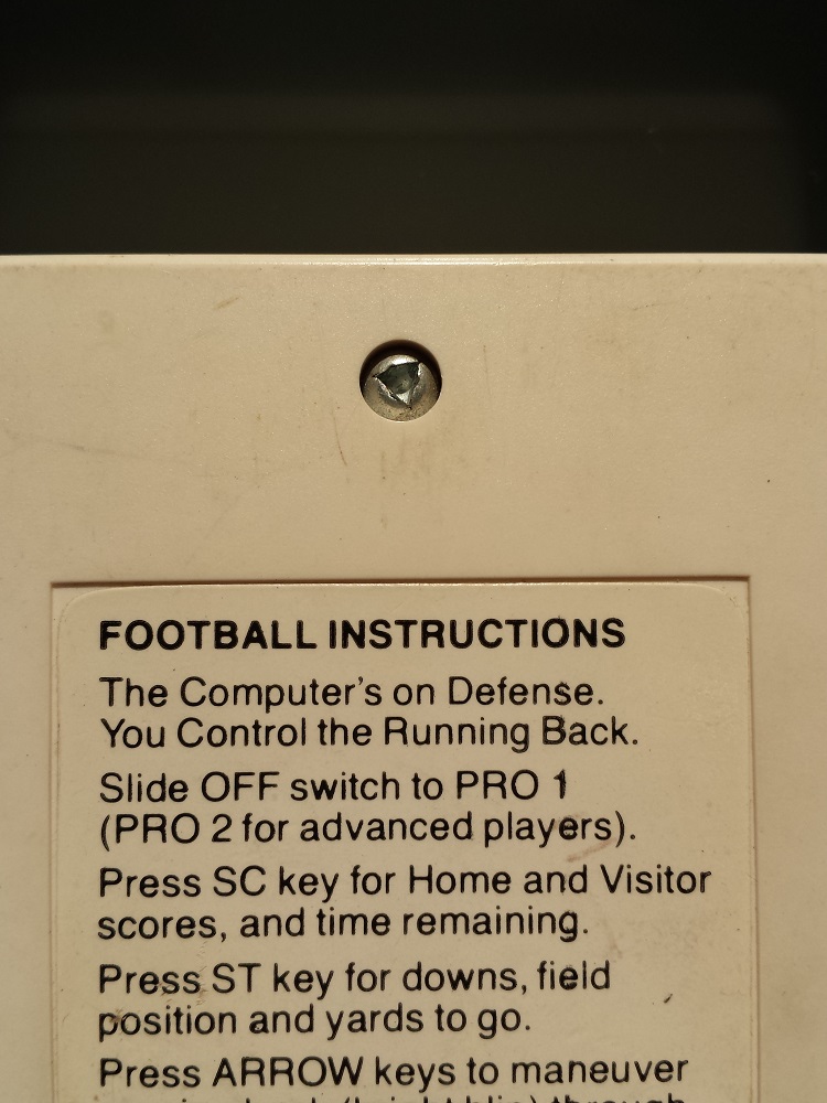
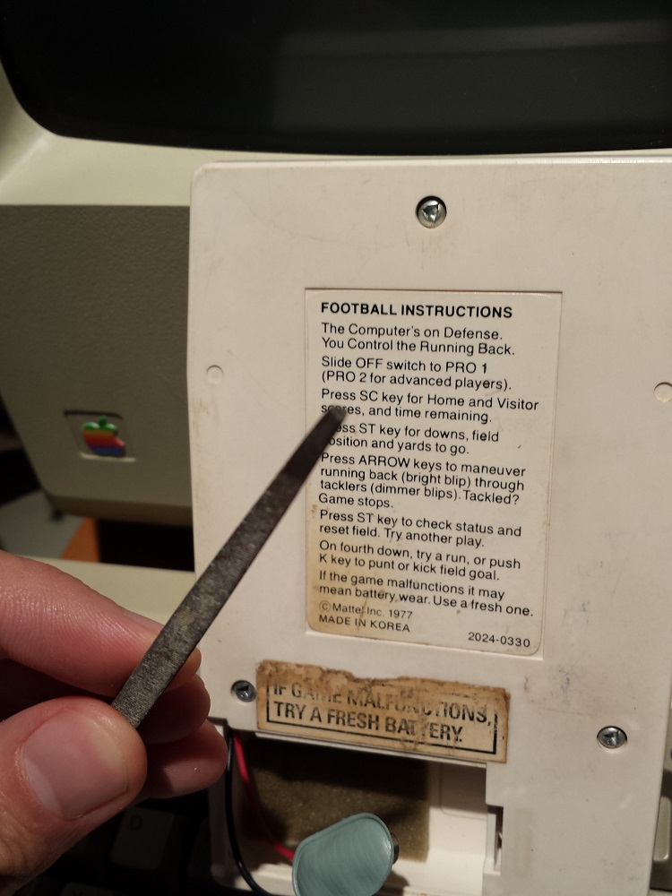
I searched the web to see if anyone else had a solution for the triangular screws. One person claimed they could be removed with a flat blade screwdriver, inserted just so, but nobody else was able to duplicate this feat. Certainly it didn’t work for me. Other discussions centered on making a custom screwdriver blade. In desperation I went rummaging through my toolbox, and discovered a three-sided file whose pointed end was exactly the right shape and size to fit the screws. Hooray!
Mattel’s Secrets Revealed
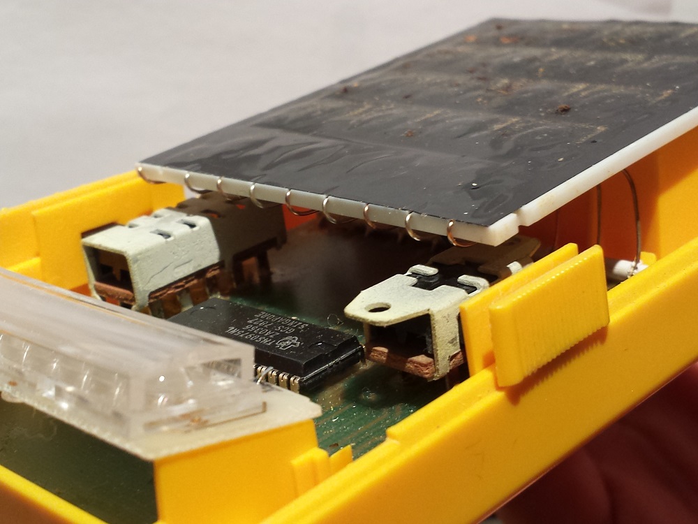
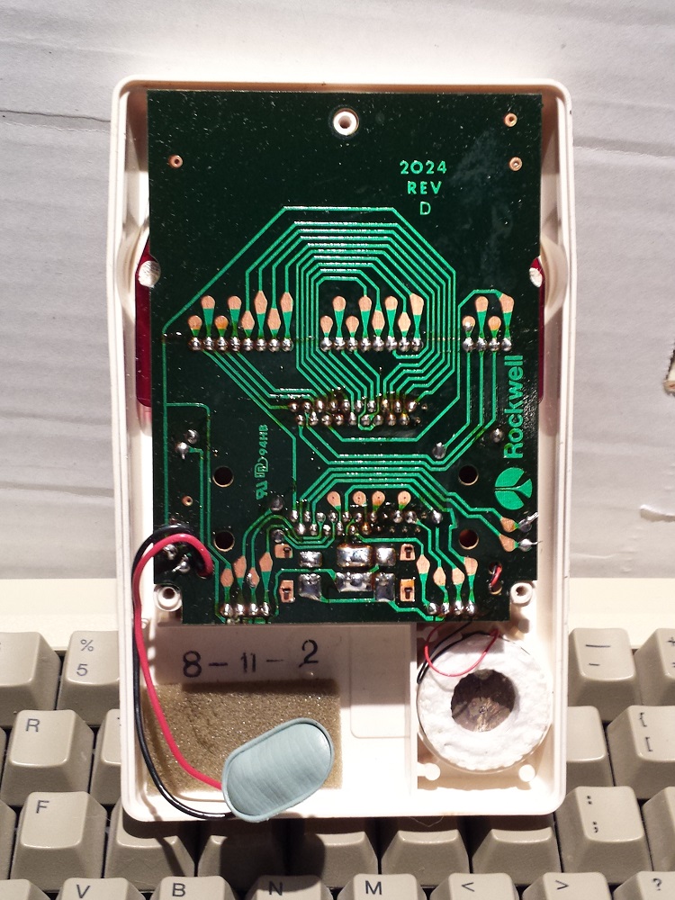
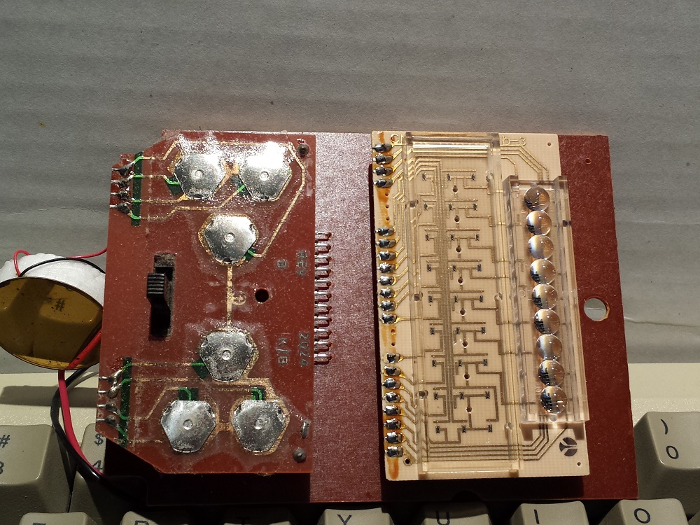
Once opened, the Electronic Football case revealed a single low-density board with the Rockwell International logo, and an attached speaker. By carefully removing the board and turning it over, I exposed Mattel’s hidden secrets. As with the Little Professor, there were surprisingly few components inside: just a membrane keyboard, an LED display, a slide switch, a resistor and a capacitor, and one mystery chip. The LED display was an interesting affair, with a calculator-style 7 segment display matrix in one half, and a 9 x 3 LED “football field” in the other.
Unfortunately the mystery chip was obscured by the keyboard, which was soldered in place, and I didn’t want to do anything destructive to gain better access to it. According to information I later found on the web, it’s a Rockwell B6100-15, which is a modified calculator chip not unlike the brains of the Little Professor. Further details were revealed in this interview with Mark Lesser, the Rockwell engineer who designed the circuitry and wrote the software for Electronic Football. Development was challenging, as the chip only had 512 bytes of program memory, and the assembler ran on a mainframe computer at Rockwell. The program was entered as a batch job using IBM computer punch cards.
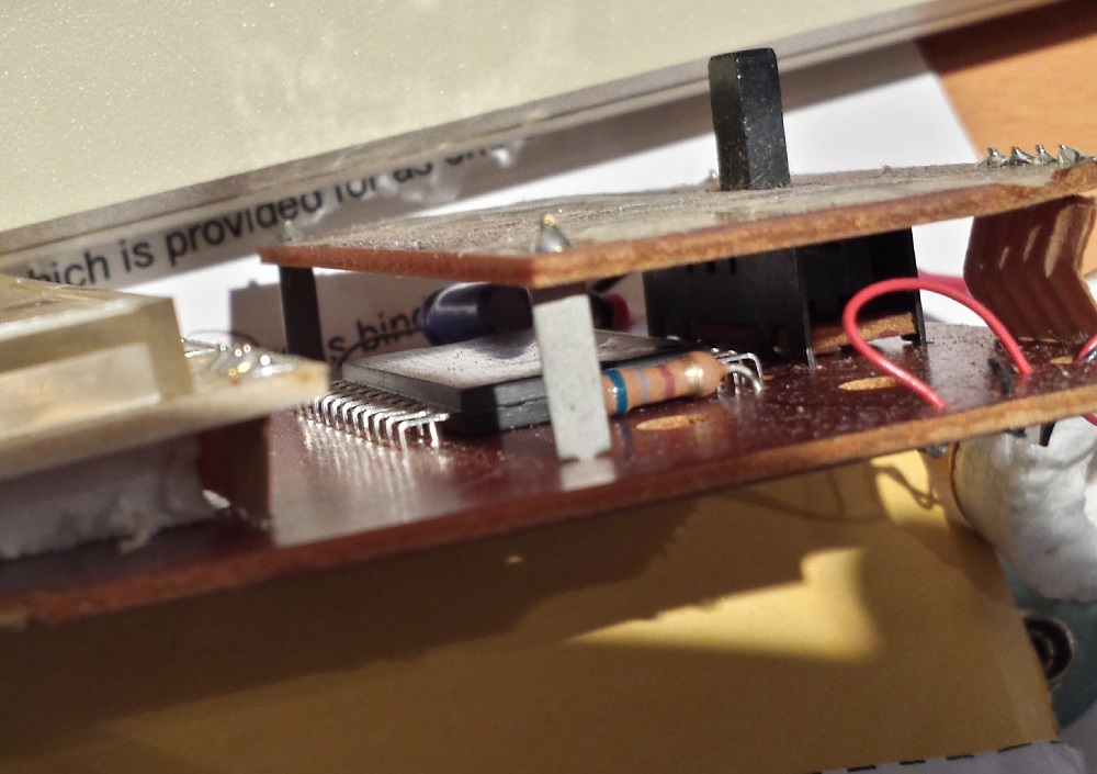
I never found a satisfactory explanation for how the playfield blips were switched between dim and high brightness, providing three possible states for each blip: off, dim, or bright. This implies a changing voltage across the LED, but the LEDs were driven directly by the Rockwell chip, which presumably had digital outputs with only two states.
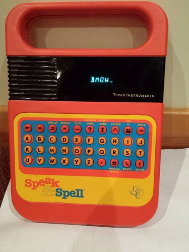
Speak & Spell – Texas Instruments (1978)
Texas Instruments released Speak & Spell in 1978. Looking back on it 35 years later, it’s hard now to appreciate just what a huge sensation it was. It talked! While today every phone and camera seems to have voice features, in 1978 this was unheard of. Some earlier toys like Chatty Cathy managed a few phrases of pre-recorded speech stored on tape or miniature phonograph discs, but nothing matched the verbosity or sophistication of Speak & Spell.
When E.T. used a Speak & Spell to phone home in 1982 (along with an umbrella, a circular saw, and some other junk), its lasting popularity was ensured. It became an international success, released as La Dictée Magique in France, Grillo Parlante in Spain and Latin America, and Buddy in Germany. Speak & Spell eventually went through many revisions, switching to an LCD display and a different keyboard, among other changes. The original 1978 version with blue vacuum fluorescent display is shown here.
The premise of Speak & Spell was simple. A synthesized voice would prompt the player for something like “spell ocean”. After dutifully typing O-C-E-A-N, the player would hear “that is correct”, followed by another word. A mistake would result in hearing “wrong” or “that is incorrect”. There were just enough alternative phrasings for correct/incorrect words to keep it from becoming repetitive, and the total spelling vocabulary was about 200 words. Expansion modules placed in the battery compartment could add a new vocabulary of an additional 200 words.
Under the Hood
As expected, the guts of Speak & Spell proved to be substantially more complex than either Little Professor or Electronic Football. After removing the back cover, I found a medium-size board connected to a speaker, with an expansion module attached. Hidden underneath were two membrane keyboards, one for each half of the button array on the front panel.
Removing the circuit board was more difficult than it first appeared. It was attached to the keyboards with stiff copper wires, and the keyboards were held on the front cover by plastic clips. Gentle prying on the plastic clips failed to release the keyboards, and more robust prying broke off two of the clips. $@&*#! After a lot of patient poking and wiggling and bending, I was finally able to remove the circuit board and keyboards, and flip them over to reveal the heart of the beast.
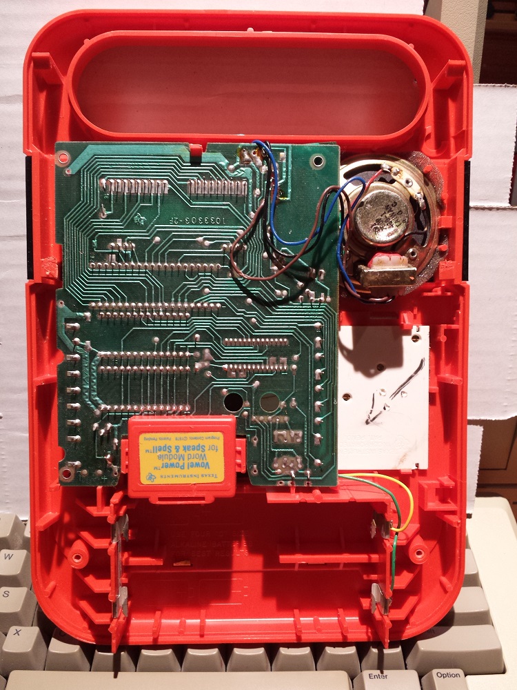
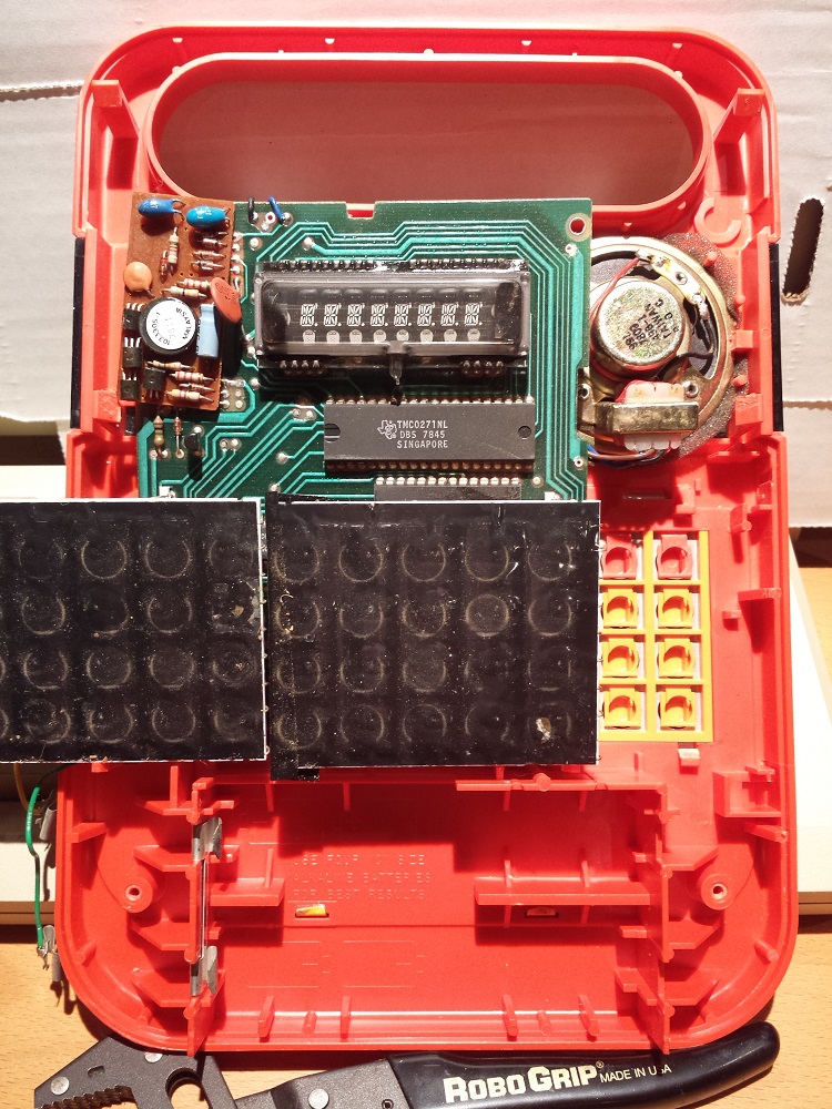
The brown board at top-left of the photo is the power board. It turned out to be a miniature switch-mode power supply, tucked inside the Speak & Spell! The rest of the goodies are on the green logic board, including the eight-character VFD display, and four custom TI chips. This is where all the magic happened.
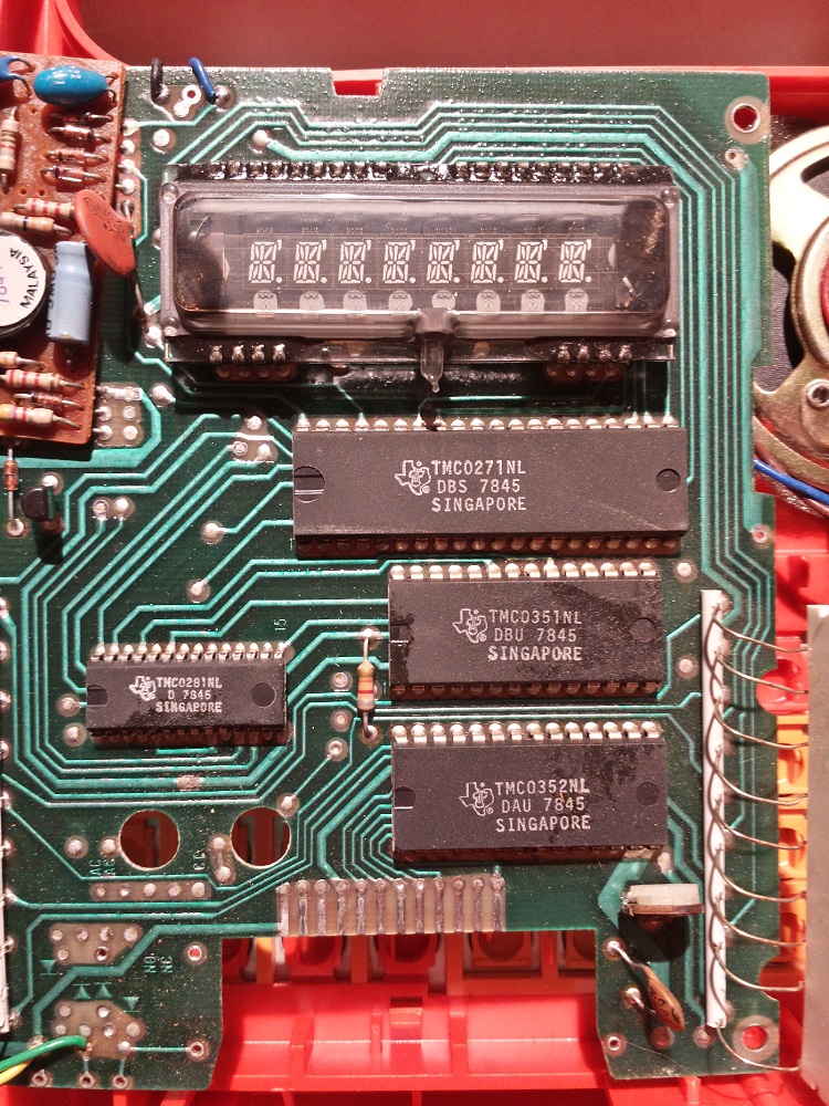
Closest to the display is the 40 pin TMC0271 microcontroller, another member of the TMS1000 family. This 4 bit MCU had 2KB of program ROM, and 128 nibbles of RAM. Each instruction took six clock cycles to execute, at nominal clock speed of 320 kHz, for total throughput of 0.05 MIPS. It wasn’t blazing speed, but it got the job done.
At left and below the MCU is the 28 pin TMC0281, which was TI’s new single-chip voice synthesizer. More about this in a minute.
Below the MCU to the right, there are two ROM chips labeled TMC0351 and TMC0352. These 16KB ROMs were the largest available at the time, and were used to store speech data. Another 16KB ROM was discovered inside the expansion module when I cracked it open – this one labeled TMC0350. These ROMs didn’t have standard parallel or serial interfaces, but were strange designs containing an address counter and control circuitry in addition to the memory. By tracing the circuit board, other hackers have learned that the ROMs don’t interface to the microcontroller at all, but are driven directly by the speech synthesizer. Maybe that explains their strangeness.
Making it Talk
So how did Speak & Spell create human-sounding speech? It represented words as a series of phonemes, each one 25 milliseconds long. Each phoneme was generated by seeding the voice synthesizer with appropriate data. The synthesizer contained two audio oscillators. A periodic “chirp” oscillator produced a sound like a man saying “uhhhhh”, and was used to create voiced phonemes like the letter “O”. A separate noise oscillator was used to create unvoiced phonemes, like the letters “T” or “S”.
By controlling the volume and pitch of the oscillators, and further tuning their sounds by using a 10th order digital filter, a wide variety of speech-like sounds were possible. Encoded speech was very compact, requiring at most 12 numbers per phoneme: volume, pitch, and the 10 filter coefficients. By using repeat flags and omitting filter coefficients in some circumstances, the data was reduced still further. The average bitrate of speech encoded this way was about 1000 bps (125 bytes/sec). Thus the 16KB ROMs each provided space for about two minutes of encoded speech. Many more details on the synthesizer and the encoding mechanism can be found at furrtek.org.
In theory, it was possible to create synthetic speech by sitting in a quiet room and authoring synthesizer coefficients by hand until the desired sound was achieved, but this approach was incredibly time-consuming. Instead, Texas Instruments used a mainframe computer to analyze recordings of real human speech, and map them to the closest synthetic phoneme for each 25 ms interval. A radio DJ from the Dallas area was chosen as “the voice of Speak & Spell”, because his monotone delivery and deep voice could be efficiently encoded.
Speak & Spell was a fascinating product, with many more interesting details than I’ve described here. For more, check out this great technical article by one of Speak & Spell’s original designers at cnx.org.
Read 3 comments and join the conversation
Raspberry Pi
A friend from work gifted me a Raspberry Pi Model B. I was generally familiar with the RPi, but hadn’t had a chance to look at it in detail before now. The specs are impressive: a 700MHz 32-bit ARM CPU, 256MB RAM, USB, audio, composite video, HDMI video, and SD card support. It’s also got GPIO headers as well as headers for I2C and SPI, so you can interface it with various sensors and other external elements.
The Raspberry Pi has proven to be extremely popular since its release, and appears to have made major inroads among the Arduino community. But the further I looked into it, the more confused I became about who this product was intended for. Perhaps the hardware specs are a little too good: it’s nearly the equivalent of a standard Linux PC from 10 years ago. That’s an amazing thing to fit onto a tiny board that costs $35, but is it fun to use?
What I enjoy most about my projects is interfacing with hardware at a very low-level. I get a kick out of bit-banging video, replicating retro electronics, and interfacing with odd hardware with specific timing requirements. I don’t really want to run X-Windows on my embedded project, or use it as a development IDE platform. When it comes to digital bit-twiddling, the lowly Arduino still has more GPIOs, and offers real-time control of the IO pins. The RPi can’t really match that, running garbage-collected Python programs on top of a multi-tasking Linux kernel.
If you’ve got a Raspberry Pi and found it useful, what kind of projects did you use it for, and how do you see the RPi’s strengths and weaknesses in comparison to other embedded hardware?
Read 9 comments and join the conversationA New Kind of Video Game Console

A few months ago I posted a long essay on my professional future. Should I try to make a career of BMOW blogging? Find an electronics industry job? Return to video game development? Launch a start-up company? Since then I’ve been engaged in many parallel paths, trying to do all those things at once. I’ve drafted business plans, pitched to Sand Hill Road venture capitalists, taken countless coffee meetings with angel investors, rubbed elbows at meet-ups, and generally abused my network of friends, their friends, and their friends’ friends for any worthwhile leads on interesting opportunities. It’s been a crazy, exciting, and confusing time.
I’m happy to say that all those parallel paths have finally converged, and this week I joined Kickstarter wonderkid OUYA as Head of Engineering! It’s software + hardware + games, and I could hardly imagine a better opportunity. OUYA is a $99 video game console, based on the Android OS, where all the games are free downloads. By removing the roadblocks associated with traditional console development, it opens up the TV as a platform to smaller indie developers for the first time. Every OUYA console is also a dev kit, so there’s nothing more to buy. It’s built on Android, so developers already know how it works. Gamers benefit from increased variety and the ability to try any game in the OUYA catalog before purchasing additional in-game content. Hackers are welcome, and rooting won’t void your warranty.
The hardware is based on the Tegra 3 SoC, which combines a quad-core ARM processor with an nVidia GeForce GPU. This is the same chip used in Android tablets like the Google Nexus 7 and Asus Transformer Prime. Those who don’t follow mobile technology closely will be amazed at how powerful this hardware is. Placed in a game console with HDMI output, and freed from concerns about battery life, the Tegra 3 can compete on the level of the Playstation 3 and XBox 360. The bluetooth controller combines analog sticks, buttons, and a touchpad, and boasts a beautiful industrial design from fuseproject’s Yves Behar.
OUYA launched its Kickstarter campaign earlier this summer, and blew past its funding goal within the first few hours, eventually raising more than $8 million in pledges and pre-orders. The response from both gamers and developers has been overwhelming. Clearly the OUYA concept has struck a chord within the community. There’s been some understandable skepticism about OUYA in the press, suggesting it’s a group of well-meaning amateurs with no hope of actually delivering on its promises. But after digging into the details myself and getting to know the leaders of the company, I can tell you nothing could be further from the truth. I’m confident in betting my own future on its success.
This is a hardware blog, so I need to emphasize that I’ll be running the software development part of OUYA’s business. The hardware development is in the capable hands of Muffi Ghadiali, a veteran of past consumer electronics projects such as the Kindle Fire and HP TouchSmart computer. nVidia and its Asian manufacutering partners are also a huge source of assistance. So I won’t be breaking out my soldering iron at the office, but my background in electronics means that I can work effectively with the hardware team. And I get to geek out with pre-release hw prototypes!
My task is to finish development of the OUYA SDK, the console’s browser/store interface, the developer portal web site, the payment system, and all the other technology that’s needed for the March 2013 launch. I’ll be doing all this with a team operating from a satellite office in the San Francisco Bay Area (marketing, sales, and OUYA’s corporate office are in Los Angeles). This is much the same kind of work I’ve done in the past at Trion Worlds and Electronic Arts. At Trion we built the MMO RIFT, which was a great experience in leading a team to build a complex online service from scratch. And at EA I created many console games for the Playstation, XBox, and other systems, and I know what a pain it is to deal with the balky dev kits, tools, and mind-numbing technical requirements. I’m thrilled to be introducing a new kind of video game console that will open up the TV platform like never before.
Read 7 comments and join the conversation
Procrastinating the Future

Frequent BMOW readers have doubtless noticed the lack of project progress lately. I could claim I’ve been trapped under a piece of heavy furniture, but the truth is I’ve been procrastinating while trying to set a new course for my professional future. That’s a fancy way of saying I’m busy looking for a job. But I can’t post an update here without at least some topical content, so here are the two editor’s choice blue ribbons that BMOW won at the 2009 Bay Area Maker Faire. O’Reilly Media just sent them yesterday, and posted a complete list of winning projects, even though the event was almost three years ago. Their “to do” backlog must be as long as mine!

Despite the contents of the BMOW web site, I’ve never had a professional job in electronics or computer hardware. My career has been in software development, with most of it working in the video game industry in engineering leadership and management roles. Most recently I was involved with the launch of RIFT, a sprawling fantasy MMO game that took five years to develop. I was one of the first employees, and I led the engineering team that developed all the client, server, tools, and other technologies from the ground up. It was an incredible experience, and the game has raked in money since its launch, but I’ll never again run a project whose development lasts half a decade.
For the past several months I’ve had no job, by choice. This has been hard on my finances, but it’s provided me an opportunity to consider lots of interesting and unconventional ideas for the future.
Make BMOW a career.
My first instinct was to turn the BMOW projects into a self-financing operation, creating a micro-business from the sales of project hardware and advertising revenue from the web site’s content. You’re probably already familiar with many such operations, like Evil Mad Science, Dangerous Prototypes, and Modern Device. I may still give this a shot, but my guess is that BMOW projects are best off remaining as a hobby. I’d hate to be forced to make all my projects “useful” in a commercial sense. I doubt there’s much market for hand-made 8-bit computers, for example, even if designed as an educational kit for nerds. And I don’t like the idea of filling the web site with a bunch of advertising crap.
Find an electronics job.
If turning BMOW into a business isn’t the answer, then maybe an engineering job at a hardware or electronics company is a better solution. The San Francisco Bay Area is a pretty good place to find such companies, after all. I looked into the options in this space, but came away disappointed. Without an electrical engineering degree or any past professional experience working in electronics, I would have to argue my qualifications based solely on my hobby project experience. Some companies might consider that favorably, but most would not. And even if I could land an EE job, a hands-on hardware engineer role would be something of a step backwards on the career ladder for me. Better would be a technical management job at a company making hardware or software/hardware products, but I don’t think anyone would hire me to do that without past domain-specific professional experience.
Continue on the software or gaming path.
The most obvious route is to continue on my current path, and seek an interesting technical leadership role at a game developer or web-based business. In fact this is what I’ll most likely end up doing. I’m very fortunate that there are many good options for me in this area, and I have plenty of personal contacts at local companies, so it’s more a question of finding the best fit than of finding any job at all. My LinkedIn profile says I’m seeking opportunities that combine technical leadership with wider product development and business responsibilities. Translation: a software technology-oriented role that isn’t exclusively about engineering, but more about the whole product. If you’re in the San Francisco Bay Area and have any leads to share about such positions, let me know.
Bootstrap a software business.
Another option I’ve considered is building a niche software product by myself, and turning it into a small business. With low development costs (primarily just the cost of my own time), the business wouldn’t need a tremendous amount of revenue in order to be successful. I have a few ideas in particular involving casual strategy games for kids, and I may pursue one of these even while I continue to examine my other career options. Bootstrapping isn’t my preference, though. I prefer working with teams to working alone, and the quality level I could expect to hit would certainly be lower for a solo project than for something developed by a team of experienced developers. I’m also acutely aware that having a couple of game concepts doesn’t constitute a meaningful business plan.
Launch an investment-backed startup.
The startup company concept is deeply embedded in Silicon Valley’s culture, yet it was only recently that I began seriously considering it myself. Having now been an early employee (non-founder) at three startups, and having lots of friends and colleagues who’ve done it successfully themselves, I’ve slowly realized that successful founders are just smart, motivated people not very different from myself. I have a few friends at venture capital and investment banking firms to whom I could bring ideas, and many more well-placed friends-of-friends I could meet with an introduction. From a practical standpoint, then, getting my foot in the door of the startup dating game wouldn’t be difficult. Investment backing would enable hiring an experienced team to build a high-quality product, and would also bring referrals to potential cofounders with the operations, financial, and marketing skills that I lack. What’s missing is a compelling product idea, and perhaps another cofounder or two with a complementary background to my own. I’ll be working on both of those needs over the next few weeks.

Been there, done that?
Why am I analyzing my professional future here, as if it were an interesting circuit to debug? My reasons are selfish: I’m hoping for your advice. Have you been in a similar situation with your own career? Ever tried to turn a hobby into a vocation? Ever bootstrapped a product, or launched or startup? How did it go, and what did you learn from the experience?
Read 6 comments and join the conversation
Extreme Product Testing
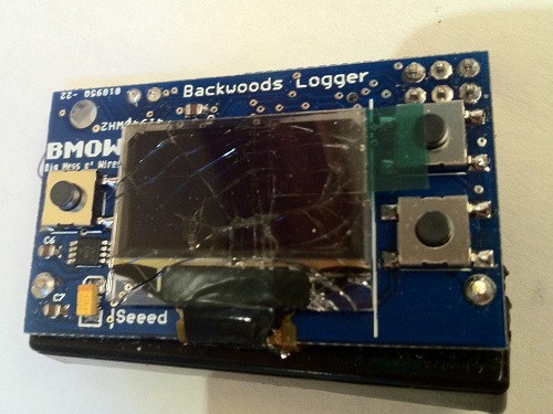
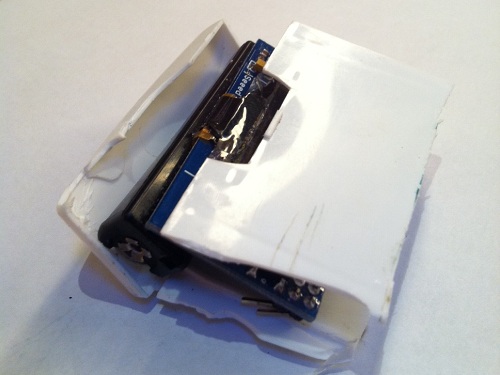
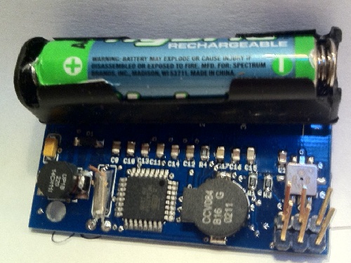
Have you always wondered what would happen to a Backwoods Logger Mini if it were crushed under your own body? No, neither have I, but today I found out anyway. I took out one of the newly-assembled Mini prototypes for a trail run, stored securely in a plastic case in my hip pocket. I wish I could say I was chased down a cliff by a mountain lion or something equally exciting, but the truth is that I tripped on a sidewalk crack before I even made it to the trail. I was running downhill and moving pretty fast, so I went skidding and bumping down the sidewalk with pieces of my hands, knees, elbow, and hip left behind on the concrete. As I hobbled back home, I heard some ominous rattling noises in my pocket. Not good…
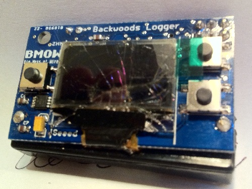
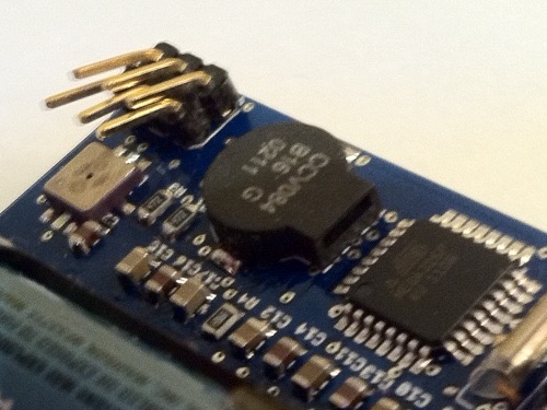
Further examination releaved the sad truth: the Mini took a direct hit when I fell, with all my body weight coming down on it, crushing it between my hip bone and the concrete. The plastic case was completely destroyed and smashed to pieces. The OLED glass was crushed, and part of the ribbon connector ripped off. The NEXT button was flattened and the spring mechanism killed. On the back of the Mini, the header pins were bent nearly 90 degrees over, the negative battery terminal was ripped straight off the board, and a bit of wood got stuck in the RTC crystal.
No, it does not still work.
I’m upset at having lost a prototype, since they take considerable time to assemble and the parts aren’t cheap. At least this makes a more interesting story than losing a prototype to a soldering error!