Archive for the 'Bit Bucket' Category
Too Many Macs!
While I’ve been working on the Plus Too Macintosh replica, I’ve also collected a few real vintage Macs in the past couple of weeks. Too many, in fact, so it’s getting hard to even walk through my office due to the Mac paraphenalia everywhere. The trouble is that once your friends hear you’re collecting vintage Macs, they’ll start giving you perfectly good systems for free! Here’s the current inventory:
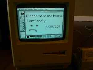
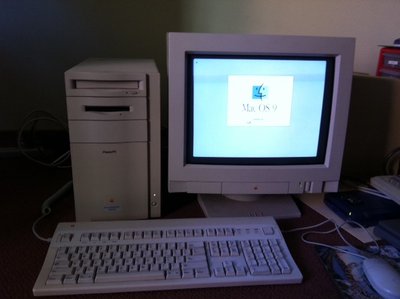
Mac Plus – aka “Lonely” – I bought this Plus from a Craigslist ad with the photo shown above. It’s in nice working condition, and has only moderate yellowing of the plastic. I’ve paired it with an older Apple M0110 keyboard, which actually predates the Plus. After an upgrade to 4MB of RAM and the addition of a 100 MB external Zip drive, Lonely is in business! The Plus is running System 6.0.7 and has a 68000 CPU running at 8 MHz.
Mac 512Ke – aka “Smelly” – This was another Craigslist purchase, acquired from a guy who was once a Mac repair tech in Japan. He threw a whole box of spare Apple ICs into the deal for free. This machine earned its nickname from the horrible burning smell it gave off when I first turned it on. In an attempt to pinpoint the problem, I later ran it outside with the rear cover off, but the smell never returned and Smelly has worked fine ever since. It’s paired with an Apple M0110A keyboard (the one with the numeric keypad) with a couple of broken keys. The 512Ke is basically a Plus with no SCSI and only 512K RAM, but the CPU specs are the same.
Macintosh Classic – I was given this machine for free, which is good because it has lots of problems. It does mostly work, but there’s no sound, and it sometimes fails to boot up and shows a checkboard pattern on the screen. I believe both of those problems are due to aging capacitors on the motherboard, which could be replaced if I were motivated enough. The floppy drive doesn’t work, and seemingly half the keyboard keys are broken. It’s got a 40 MB internal hard drive and 4 MB RAM, and the same CPU as the Plus and 512Ke. I’ll probably cannibalize the HD and RAM, and recycle the rest.
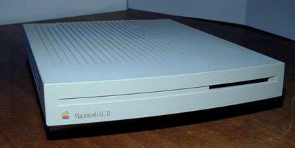
Macintosh LC II – I bought this pizza box machine cheaply from a vintage Mac web site. The specs are good: 68030 at 16 MHz, 12 MB RAM, 1 GB hard drive, and ethernet card. Unfortunately it’s a real dog running System 7.5. I used to own an LC myself, and I don’t remember it being this slow. It can take nearly a second for the computer to respond to mouse clicks on the tool strip! I haven’t been able to get the ethernet card working, although I haven’t tried very hard. I plan to install System 7.1, and see if that helps improve performance at all. If not, I’ll probably swap out the 1 GB HD for the Classic’s 40 MB one, and re-sell or donate this machine.
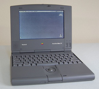
Powerbook Duo 230 – This was another freebie. The Duo 230 sports System 7.1, 12 MB RAM, a 120 MB hard drive, and 16 glorious grays. The 33 MHz 68030 CPU feels relatively snappy. Unfortunately without a Duo dock or mini-dock, the only way to get data on and off the Duo is with a LocalTalk network connection. Even if I had a dock, though, the flakey keyboard makes it challenging to use. All of the keys work, but many of them have to be pressed very hard to register a keypress. This is a common problem with Duo keyboards, and I followed the instructions to disassemble the keyboard and clean the contacts on the mylar membranes, but it didn’t seem to help much. I’ll probably donate this machine.
Power Mac 8500 – This Mac is awesome, and I got it for free! There’s something about the vintage tower Macs that’s just irresistable. With a 120 MHz Power PC 604 CPU, 160 MB RAM, and System 9, it’s actually capable of running semi-recent software. It’s only problem is that it’s as loud as an airplane. I think the hard drive mount may be vibrating, which should be simple to fix. If one of the fans is failing, it may be more difficult to find a replacement.
I was able to get online and browse the web using the 8500, although no recent web browser will run on this machine, and the browsers that do run on it (Internet Explorer 5… ahem) have trouble rendering many web pages from 2011. Even when the pages do render correctly, it is S…L…O…W… These days, even a simple web page is likely to involve downloading dozens of individual image and style sheet files and running a bunch of JavaScript. I plan to keep this machine for general Mac nostalgia use, and as a file server for the Plus and 512Ke.
Piles of Peripherals
I’ve got external Zip drives, assorted RAM, system saver fans, SCSI cables and terminators, serial cables, LocalTalk cables, and a bunch of other stuff that I can’t even identify. I need to learn to say no to donations, even when they’re free!
Read 4 comments and join the conversation
Soldering, with Profanity
Hot diggety damn! I believe I’ve successfully soldered the Max II in its cruel 100-pin package with 0.5 mm pin spacing. At least, I’ve assembled enough of the board to connect it to a JTAG programmer, program an LED blinky routine to the Max II, and confirm that it works. There could still be all kinds of pins shorted or broken, of course, but at least I know I didn’t fry it completely.
Soldering that chip wasn’t fun. It took me about two hours just for that single TQFP 100. I used the drag soldering technique, where you goob tons of solder onto the pins and create pin-to-pin solder jumpers like crazy, then go back afterwards with solder wick to clean up the jumpers. At least that’s the idea.
I had the absolute worst time trying to wick away the jumpers. No matter what I did, the extra solder on the pins wouldn’t soak into the solder wick. I set the wick on top of the pins that had jumpers, then set my iron on the wick, and pressed down onto the sandwich. The solder underneath the wick would melt, but it wouldn’t go anywhere. When I removed the iron and wick, the jumpers remained right where they’d been, with nothing at all soaked into the wick. I applied flux everywhere, over and over, but it didn’t help.
This pattern went on for ages, and I got more and more upset. I started swearing at the board, using every profanity I could think of. I had to close the windows so the neighbors wouldn’t hear. After a while, I started singing random profanities to the tune of opera while I worked on the jumpers. I burned the soldermask off several of the traces, burned the board, and re-heated the same pins so many times that I was certain nothing was left inside the chip but melted slag. All in all, it was not a good time.
Eventually I stumbled onto a few techniques that helped a little, raising my wicking success rate from 0.1% to maybe 20%.
- Some jumpers can be cleared simply by touching the iron briefly to the pins, without any wick.
- Don’t stretch out the wick braid. Keep the strands pressed together, like stranded wire.
- If a stubborn bit of solder refuses to be wicked away, add more solder. A huge glob is actually easier to remove than a tiny fleck.
Assuming the other as-yet-untested pins on the Max II are OK, then assembling the rest of the board should be cake.
Read 4 comments and join the conversationLow-Power LCD Smackdown
 Sometimes it seems like there are a million different LCDs you might use with your microcontroller project, and deciding on one can be hard. Once you’re ready to move beyond a basic text display, you’ll find graphic displays have a dizzying number of options for technology, color depth, interface type, driver, and power. Recently I’ve been collecting info on display options for my own projects, and here I’m presenting three options that look promising.
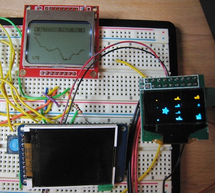
The Nokia 5110 is a low-resolution monochrome LCD that’s cheap and extremely low-power. A family of small monochrome OLEDs provide crisp, bright displays with a bit more resolution, in a teeny-tiny package. A 1.8 inch color TFT provides even greater resolution and 18-bit color, while still limiting power to about 90 milliwatts.
 Nokia 5110
Colors: monochrome
Resolution: 84 x 48
Active display area: 2.8 x 2 cm
Interface: SPI
Power: 3.3v
Current: 0.4 mA for logic, 1-10 mA for backlight
Cost: $10
Vendors: Sparkfun, Adafruit
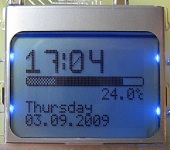
This is the display I’m currently using for my Backcountry Logger project. It’s cheap, easy to use, and consumes very little power. You don’t really need the backlight for daytime visibility, and with backlight off, it consumes just 400 uA! Awesome for battery-powered projects. Just 1-2 mA worth of backlight current is plenty for night-time visibility too, although more would be nicer. This puts the display well within the capabilities of a single CR2032 coin cell.
Working with the display is simple, as long as you remeber it’s a 3.3v device and not 5v tolerant. There are lots of great tutorials and examples available for this display, including this nice one from Adafruit. Communication with the display controller uses SPI. Writing a single byte sets 8 pixels at a time, so pixels are not individually addressable. If you’re mostly displaying text or bitmaps this isn’t a problem, but if you need a more complex image consisting of many overlapping elements, you’ll need to composite them in software before sending the result to the display.
The weak points of the Nokia 5110 display are resolution and looks. The contrast and sharpness are pretty good for a display of this type, but there’s still no getting around the fact that this is a low-res, dark-gray on light-gray display. The 84 x 48 resolution allows for just 14 x 6 characters using a typical 5 x 7 font (allowing for space between letters). If you seek utility, low cost, and low power, it’s a great solution. If you want something with a bit more bling, look elsewhere.
 SSD1306/SSD1308 OLED
Colors: monochrome
Resolution: 128 x 64
Active display area: 2.4 x 1.2 cm
Interface: SPI, I2C, or parallel
Power: 3.3v, and maybe 7-12v
Current: roughly 5-13 mA, depending on how many pixels are lit
Cost: $15-$20
Vendors: Sparkfun (bare LCD), Adafruit, eBay
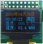
This little OLED display comes in a few slightly different flavors, but all of them are tiny. It’s one thing to read the dimensions (0.96 inches horizontally), but another to see it in person. All three of the displays discussed here are small, but this particular OLED is smaller than a postage stamp. It’s about the size of the last joint on my thumb.
Despite its small size, the OLED display is very readable. It’s sharp and bright, and a pleasure to look at. Since it’s an OLED, there’s no backlight, and current draw varies between about 5 to 13 mA in my testing, depending on how many pixels are illuminated. The 128 x 64 resolution is a nice bump from the Nokia 5110 display, allowing for 21 x 8 characters. Communication choices are SPI, I2C, or parallel, selectable via configuration pins. Like the Nokia, each byte sets 8 pixels at a time. Adafruit has a tutorial and library.
The display controller chip runs at 3.3v, and the display itself needs 7-12v, although you might be able to get away with a single supply depending on which display variant you have.
Adafruit sells this display on a break-out board, with white pixels, with a SSD1306 controller. The SSD1306 has a built-in charge pump, and can optionally generate 7.5v for the display from a 3.3v supply, which is a very convenient option. Sparkfun sells the naked LCD, with white or blue pixels, and a SSD1308 controller that lacks the charge pump. You’ll need to mount the 0.5 mm pitch connector somehow, and provide a separate power supply for the logic and display. The most common eBay variant comes on a break-out board, with the SSD1306 controller, and yellow pixels in the top quarter and blue pixels in the bottom three quarters. Mine also came hard-wired to use the parallel interface, and switching to SPI required wicking away some solder jumpers and adding new ones.
This display meets a narrower range of needs, but is awesome for its target niche. I’m strongly considering doing a version 2.0 of the Backcountry Logger using this display, to gain the benefit of smaller size, higher resolution, and better looks. Unfortunately with the amount of current it needs, it’s probably outside of what a CR2032 can provide, and will require 2 x AAA or 1 x AAA with a DC boost converter.
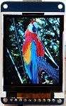 Adafruit 1.8 inch TFT
Colors: 18-bit (262144 colors)
Resolution: 160 x 120
Active display area: 3.6 x 2.8 cm
Interface: SPI
Power: 5v or 3.3v
Current: 1 mA for logic, about 26 mA for backlight (can be dimmed)
Cost: $25
Vendors: Adafruit
This is the display I plan to use for Tiny CPU. Unlike the others, it’s a full color display with individually addressable pixels. It supports 18-bit color, but can also be configured for 16-bit color or monochrome (I think? Haven’t tried that yet). It’s a bit larger than the other two, but still quite small compared to most displays. It is natively a 3.3v device, but the Adafruit breakout board includes an LDO regulator and level-shifter chip, so it can be used with 5v microcontrollers as well. Current demands are the highest of the three displays, but not excessive at about 1 mA for logic and 26 mA for the backlight. The backlight can be dimmed using PWM to further reduce the current. This is still well within the capabilities of an AAA-based battery-powered project.
The TFT is very attractive, not quite on par with the OLED, but certainly nicer than the CSTN used in some other cheap color LCDs. The 160 x 120 resolution feels giant in comparison with the previous displays, allowing for 26 x 15 characters. The display controller allows for a few different protocols, but the break-out board hard-wires it for SPI.
With the larger resolution and greater bit depth, a screen’s worth of data requires many more bytes than the previous two displays. Depending on the speed of your microcontroller and SPI interface, this may result in noticeably slower refresh times. I tested it using hardware SPI on a 16 MHz Arduino, and found the refresh time to be acceptable.
Adafruit has a nice tutorial and library for working with this display (I’m sensing a theme here). Unexpectedly, the breakout board also has a micro-SD card reader on it. Ignore it, or use it as a bonus peripheral in your next project.
Read 6 comments and join the conversationLiving on the Edge
I just applied 4 years worth of WordPress updates in one go, without making any backups first. What could go wrong?
Be the first to comment!Maker Faire 2010
Ah, Maker Faire. It’s part garage inventions, part Burning Man reruns, part techno-supermarket, and all awesome. Can it possibly be a year already since Maker Faire 2009, where BMOW was featured in Wired, Slashdot, Digg, etc. and I talked myself hoarse in a 48-hour marathon of CPU conversations?
This year I headed back to the Faire as a visitor rather than an exhibitor, so I’d actually have a chance to see the cool stuff I missed last time. The show has actually grown since last year, which I didn’t think was possible, but they annexed a neighboring county or something and added even more exhibits than before. This event is big, big, big. It’s almost too big. After a few hours my brain was fried, and I just couldn’t appreciate all the awesome stuff anymore. I think there were at least three different robot death-matches, ten 3D printers, and dozens of Arduino add-ons.
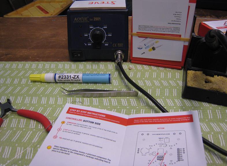
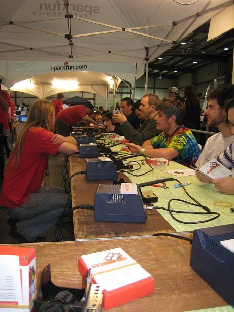
My major goal for the show was to do SparkFun’s SMD soldering class. I made a beeline to the SparkFun tent as soon as I arrived, and after a short wait, I sat down with eight other solder artists to construct SparkFun’s Simon kit. Here are a few pics of the setup:
After a short introduction, we jumped right in, and I soldered the first tiny IC without any problems (1 mm pin spacing). But at step two, a surface-mount capacitor, the wheels came off the cart. I just couldn’t get the cap to stick to the pad, after at least ten attempts, and eventually I overheated the cap to the point where it disintegrated. I sheepishly asked for a replacement, which took a while for them to find, and it took even longer for me to successfully solder it in place. Everyone else in the class was well ahead of me, and I was beginning to feel like a dummy.
After a few more steps, I soldered in the battery terminals, and was ready for the first major checkpoint: test for 5V. Unfortunately, this was when I discovered I’d soldered the battery terminals onto the wrong side of the board! One of the instructors took it to a rework station to fix it, which took a mysteriously long time, and when he came back I had a burned board with one trace lifted off the PCB. Argh. Eventually I was able to repair it with a jumper wire, and it passed the 5V test. But we were now an hour and a half into the class, and many of the other people were already done, just awaiting their turn to have the Atmega on their Simon board programmed.
I kept working, while the people on either side of me debugged their boards. After programming, one neighbor had a board where only two lights worked, and another had regressed and no longer passed the 5V test. While they debugged, I moved steadily forward, and eventually finished the assembly. At this point, both SparkFun’s main and backup Atmega programmers broke, and they were unable to program any more boards. Not a great ending to the class.
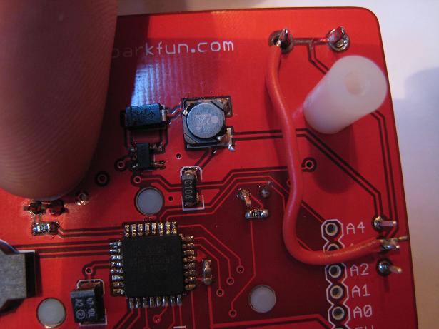
Ironically, the Atemga itself with its 0.65 mm pin spacing (I think) was actually pretty easy to solder. Just tack one corner, blob solder onto all the other pins while ignoring shorts, and then suck away the excess with solder wick. I’d say it’s the small size of the components that makes soldering them challenging, less so than the spacing of the pins. Take a look at these photos of my finished board. Some of those little surface mount passive elements are soldered in at awkward angles, but it’s the best I could do. Look at the size of my finger for reference. That tiny capacitor to the lower-right of the Atmega in the second photo is only about 1 mm long, and 0.5 mm wide… yikes! These parts make a grain of rice look giant. It’s tough to even see these things clearly. In the photo you get a pretty clear view, but with the naked eye that tiny cap is just an unidentifiable grayish speck, and whether it’s soldered properly is impossible to tell.

After the class, I wandered the Faire for most of the day, seeing lots of pretty cool stuff, but nothing that really stood out in my mind as exceptional. I enjoyed getting a chance to program an Altair 8800 using the front panel switches, but overall I think the show was just too much steam punk exploding fireball mechanical giraffe sensory overload.
As I prepared to leave at the end of the day, I stopped by the SparkFun booth once more, and they’d managed to get their Atmega programmer working again. I asked if they could program my board before I left, so I could attempt to debug the inevitable problems later at home. They did, but instead of a debugging puzzle, I got the happy “beep!” of a working Simon board. No debugging needed!
HUGE thanks to the SparkFun guys. The soldering class was great, and my instructors Matt and Matt were full of help and encouragement. The class itself was a fantastic bargain, since they only ask for a $20 donation, which goes to local science-related education projects. The Simon kit sells in the SparkFun store for $25, so this was like getting a $5 discount off the kit *and* free hands-on training. Can’t beat that!
Be the first to comment!Cheetos Guitar Amp
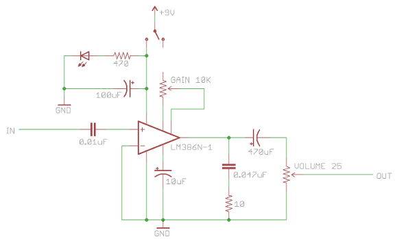
Random project for a Saturday afternoon: a guitar amp in a Cheetos Crunchy can. I followed a modified version of Make Magazine’s cracker box amp design, which uses an LM386 power amplifier and a few passive components. The amp has separate crunch (gain) and volume controls, is powered from a 9V battery, and delivers half a watt through a 2-inch speaker hidden inside the can. The whole thing went together in a couple of hours, and most of that was planning how to arrange the parts.
Now I just need to learn how to play guitar.