

Archive for the 'Floppy Emu' Category
Apple SmartPort Pin Directions
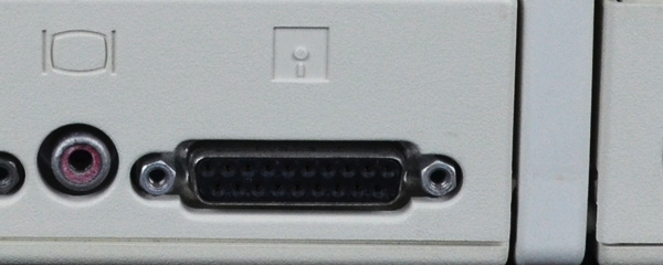
How can you deal with signals that might be inputs or might be outputs, in a way that’s safe and won’t damage sensitive electronics? In my last post I described three different types of Apple II family floppy drives. Since then, I’ve started looking further into SmartPort emulation for the Floppy Emu, which would extend 800K floppy and hard drive emulation support to the Apple IIc and IIgs. The required pinout on the D-SUB 19 pin connector is almost the same as what’s currently used by Floppy Emu, but not quite identical (inputs to the computer marked in bold):
| Pin | Floppy Emu | Macintosh | Apple II+/IIe | Apple IIc | Apple IIgs |
| 1 | GND | GND | GND | GND | GND |
| 2 | GND | GND | GND | GND | GND |
| 3 | GND | GND | GND | GND | GND |
| 4 | GND | GND | GND | GND | /3.5DISK * |
| 5 | N.C. | -12V | -12V | -12V | -12V |
| 6 | +5V | +5V | +5V | +5V | +5V |
| 7 | N.C. | +12V | +12V | +12V | +12V |
| 8 | N.C. | +12V | +12V | +12V | +12V |
| 9 | N.C. | N.C. | /ENABLE2 | /EXTINT | /ENABLE2 |
| 10 | PWM | PWM | WPROT | WPROT | WPROT |
| 11 | PHASE0 | PHASE0 | PHASE0 | PHASE0 | PHASE0 |
| 12 | PHASE1 | PHASE1 | PHASE1 | PHASE1 | PHASE1 |
| 13 | PHASE2 | PHASE2 | PHASE2 | PHASE2 | PHASE2 |
| 14 | PHASE3 | PHASE3 | PHASE3 | PHASE3 | PHASE3 |
| 15 | /WREQ | /WREQ | /WREQ | /WREQ | /WREQ |
| 16 | SELECT | SELECT | +5V | N.C. | SELECT * |
| 17 | /ENABLE | /ENABLE | /ENABLE1 | /ENABLE | /ENABLE1 |
| 18 | RD | RD | RD | RD | RD |
| 19 | WR | WR | WR | WR | WR |
Comparing the Floppy Emu pinout to the IIc and IIgs, a few pins must change from computer outputs to computer inputs. And a few other pins marked with * take on a new bidirectional behavior, being used both to control the floppy drive and to sense the type of the connected drive. All the non-power pins for Floppy Emu are connected to a CPLD, and can be switched from inputs to outputs with a firmware change, so by itself that’s not a problem. The trouble arises if you want to use a single Floppy Emu board on different computers at different times, functioning in different modes. If the Emu is configured for the wrong mode for the computer it’s presently attached to, it could damage both the Emu and the computer. Sooner or later somebody (or me) would make that mistake.
Let’s look at what this means for SmartPort emulation on an Apple IIc or IIgs. On the IIgs, pin 4 is no longer a ground pin, but instead is used to switch between Apple 3.5 drives and other types of drives. We’re not trying to emulate an Apple 3.5 drive yet, so we can safely ignore that difference and continue to use pin 4 as GND. On the IIc, pin 9 is an external interrupt. We don’t need that for SmartPort emulation, which is fortunate because it’s not even connected on the Floppy Emu end.
Pin 10 is the main problem. On the Mac, it’s an output from the computer, but on the whole Apple II line it’s an input. It either indicates the disk’s write-protect status (normal disks), or serves as an ACK signal (SmartPort). If the Floppy Emu is configured to output a WPROT or ACK signal on pin 10, and is connected to a Mac that outputs PWM on pin 10, the two chips will fight each other and cause damage. Zap!
Pin 16 is also a problem. On the Mac and the Apple II/II+/IIe, it’s either an output from the computer, or a +5V connection that will look like a constant logical 1 output. But a SmartPort device turns things around, and uses pin 16 on its daisy-chain port to determine if the next device in the chain is also a SmartPort device. It has an internal pull-up on the daisy-chain pin 16, and it checks the value on that pin. If it sees 0, that means the next device is also a SmartPort device, and if it sees 1 it means it’s not a SmartPort device or there is no device present. The IIgs may behave the same way, although I’m not sure. So in order for Floppy Emu to be detected as a SmartPort device, it may need to output 0V on pin 16. That’s another potential for two chips fighting. Zap again!
Playing It Safe
The question is how to make an Apple II SmartPort mode firmware for Floppy Emu, while avoiding potential electrical damage if you accidentally set the wrong mode on the wrong computer.
Caveat Emptor – I could do nothing. As long as you switched into Apple II mode after connecting the Emu board to an Apple II, and switched into Mac mode before disconnecting from the Apple II, you would never have two chips fighting on the same line. But that’s a poor solution. What if you borrowed a Floppy Emu from a friend for use with your Mac, and you didn’t know what mode it was in? Or you just plain forgot?
Physical Adapter – I could build a small passive adapter that sits between the computer and the Floppy Emu board. An inline resistor of about 100 to 330 ohms on pin 10 should prevent possible damage if two chips were fighting. The same solution would probably also work on pin 16, although correct functioning would depend on the value of the SmartDisk pull-up resistor and the logic threshold of the chip it used to sense the value of pin 16. But I’d really like to avoid requiring an adapter if I can. It would be so much nicer if you could just plug your Floppy Emu straight into your IIgs or IIc and have it work.
Detection – Maybe I could somehow detect whether the attached computer is an Apple II or a Mac, and only switch pins 10 and 16 to outputs after confirming it’s an Apple II. That sounds good, but how? Is there a way with the existing hardware that the CPLD could tell if pin 10 is being actively driven with some value, instead of just floating? Or maybe try to detect a SmartPort reset state before switching the pin directions? I’m not confident the SmartPort reset state won’t also be triggered accidentally by Mac drive logic like the HD20 control routines.
Button Push – I could require the user to push a button to “confirm” Apple II SmartPort mode, each time the Emu board was reset, before switching the pin directions. That would be a little inconvenient, and would still have some potential for damage if you pressed the confirmation button when you shouldn’t have. But it’s the best solution I’ve thought of thus far.
Read 8 comments and join the conversationApple II Disk Emulation
I’ve begun looking into the possibility of Apple II disk emulation with the existing Floppy Emu hardware. The recent research project into Lisa floppy emulation turned out well, so why not do it again with another vintage Apple computer? A cursory check of connector pinouts suggests it’s at least theoretically possible, though it would require major changes to the emulator firmware. But Rome wasn’t built in a day, so let’s start.
There are a confusing number of different Apple II family models and floppy drives. Some are 5.25 inch drives, and some are 3.5 inch. Some use a 19-pin D-SUB connector, and some use a 20-pin ribbon connector. Because of these differences, “Apple II disk emulation” won’t be a single emulator mode, but several different ones depending on the Apple II model and disk image being used.
This summary of Apple floppy drive models gives a nice overview. For the purposes of Apple II emulation, the drives can be organized into three categories: the venerable Disk II and its cousins (Disk IIc, Unidisk 5.25, Apple 5.25, Duodisk 5.25), the SmartPort-based Unidisk 3.5 (A2M2053), and the Apple 3.5 external drive (A9M0106).
Disk II Emulation
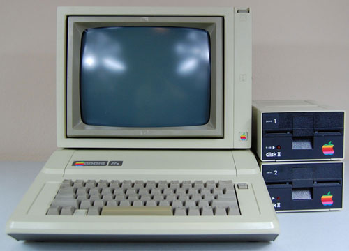
Emulation of low-density 5.25 inch Apple floppies would be useful for the Apple IIe and earlier models. These computers used a Disk II controller card in an internal slot. The controller card has two 20-pin ribbon connectors, each of which can be connected to a Disk II drive. The pinout of this 20-pin connector is almost identical to the pinout of Floppy Emu’s 20-pin connector. So with the right firmware (five words that gloss over a huge amount of work), you could plug a Floppy Emu directly into the controller card and emulate a Disk II floppy drive. Or plug two Floppy Emus into each of the two controller card connectors, and emulate two drives. With a custom multi-ended cable, it might even be possible to emulate two drives with a single Floppy Emu.
| Pin | Floppy Emu | Disk II Controller |
| 1 | GND | GND |
| 2 | PHASE0 | PHASE0 |
| 3 | GND | GND |
| 4 | PHASE1 | PHASE1 |
| 5 | GND | GND |
| 6 | PHASE2 | PHASE2 |
| 7 | GND | GND |
| 8 | PHASE3 | PHASE3 |
| 9 | N.C. | -12V |
| 10 | /WREQ | /WREQ |
| 11 | +5V | +5V |
| 12 | +5V | +5V |
| 13 | N.C. | +12V |
| 14 | /ENABLE | /ENABLE |
| 15 | N.C. | +12V |
| 16 | RD | RD |
| 17 | N.C. | +12V |
| 18 | WR | WR |
| 19 | N.C. | +12V |
| 20 | PWM | WPROT |
The only obvious mismatch is at pin 20. On the Mac, PWM is an output that controls the rotational speed of the 400K floppy drive. But on the Apple II, WPROT is an input that indicates whether the disk is write-protected. So depending on the emulation mode, pin 20 on Floppy Emu would need to behave like either an input or an output, and that’s a problem. The Emu uses a CPLD to interface with the computer, and it’s easy enough to modify the CPLD to change a pin between acting as input or output. But in practice this would be problematic and dangerous.
Let’s say your Floppy Emu board was configured in Apple II mode, and you plugged it into your Mac, with the intention of switching it to Mac floppy mode. But before you could even access the mode select menu, you’d have two outputs fighting each other on pin 20, possibly damaging the Floppy Emu, the Mac, or both. You could work around this problem by connecting the Emu to and Apple II and then switching to Mac floppy mode from there, but it would be an awkward and error-prone process. Some kind of passive adapter could probably solve this problem, with an inline resistor on pin 20, but I’d prefer to find a solution that doesn’t require extra hardware.
To complicate matters a bit more, there are two different standards for Apple 5.25 floppies. DOS 3.2.1 and earlier stored 113.75 KB per disk, 256 bytes per sector, 13 sectors per track, 35 tracks per side. But DOS 3.3 and later used a more efficient GCR encoding to store 140 KB per disk, 256 bytes per sector, 16 sectors per track, 35 tracks per side. As I understand it, this change also required a new version of the Disk II controller card. Was the newer one backwards compatible with the old format? Then there was ProDOS, which I believe used the same low-level format as DOS 3.3, but with a different filesystem. So Disk II emulation might actually involve two or three separate emulation modes, depending on the specific disk image being used.
The later cousins of the Disk II switched to a 19-pin D-SUB connector instead of the 20-pin ribbon connector, but the drive itself remained basically the same. The 19-pin connector pinout matches Floppy Emu’s 19-pin connector just as well as the 20-pin, with no problems except the collision of PWM and WPROT on the same pin. That means it should be possible to connect a Floppy Emu in Disk II mode to an Apple II with a 19-pin controller card, or with a 19-pin external floppy port such as found on the Apple IIc.
SmartPort: Unidisk 3.5
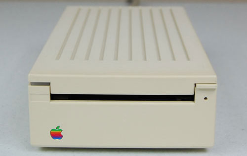
Next we have the Unidisk 3.5, an 800K floppy drive using the SmartPort communication protocol. Unlike the “dumb” Disk II, the Unidisk 3.5 was an intelligent device, communicating with the Apple II using a high-level request/response protocol that abstracted away the details of tracks and sides. From what little I’ve read about SmartPort, it sounds fairly similar to the HD20 protocol that I implemented a few months back for the Mac. It looks like there are already a couple of SmartPort-based disk emulators out there: UNIDISK and an SmartportCFA. That gives me hope that the SmartPort protocol wouldn’t be too difficult to implement.
Here’s where my understanding of things starts to get fuzzy, so if I say anything here that sounds incorrect, please let me know. It looks like the Unidisk 3.5 works on the Apple IIc, but only with certain ROM versions. There’s also a sub-model called the Apple IIc+, but I’m unclear if that’s anything more than a ROM upgrade, or what disk-related features the IIc+ offers over the IIc. The Unidisk 3.5 is also supported on the Apple IIgs, but it’s not recommended, because the performance is worse than can be achieved with non-SmartPort drives.
Did Apple ever sell other SmartPort drives, besides the Unidisk 3.5? I saw one source that mentioned SmartPort could support up to four drives per connection, and up to 32 MB per drive. If that’s true, could a SmartPort implementation on the Floppy Emu provide pseudo hard drive capability to the IIc and IIgs? I’m not sure.
How does the IIc or IIgs detect that a connected drive is a SmartPort drive, as opposed to a dumb 5.25 drive, or a non-SmartPort Apple 3.5 drive? Maybe it just sends a SmartPort request, and checks to see if anything responds. Or maybe there’s a pin that’s used to sense the drive type. The docs refer to a /3.5DISK signal on pin 4 of the 19-pin D-SUB, though I’m unclear how it’s used. More on this later.
Comparing the pinouts of the Floppy Emu 19-pin D-SUB connector with the Apple IIc and Apple IIgs, they mostly match up, but there are some noteworthy differences. There’s some disagreement about the published pinouts too, depending on which source you trust. I believe these are correct, and the Apple IIc+ is the same as the IIgs:
| Pin | Floppy Emu | Disk II | Apple IIc | Apple IIc+/IIgs |
| 1 | GND | GND | GND | GND |
| 2 | GND | GND | GND | GND |
| 3 | GND | GND | GND | GND |
| 4 | GND | GND | GND | /3.5DISK |
| 5 | N.C. | -12V | -12V | -12V |
| 6 | +5V | +5V | +5V | +5V |
| 7 | N.C. | +12V | +12V | +12V |
| 8 | N.C. | +12V | +12V | +12V |
| 9 | N.C. | /ENABLE2 | /EXTINT | /ENABLE2 |
| 10 | PWM | WPROT | WPROT | WPROT |
| 11 | PHASE0 | PHASE0 | PHASE0 | PHASE0 |
| 12 | PHASE1 | PHASE1 | PHASE1 | PHASE1 |
| 13 | PHASE2 | PHASE2 | PHASE2 | PHASE2 |
| 14 | PHASE3 | PHASE3 | PHASE3 | PHASE3 |
| 15 | /WREQ | /WREQ | /WREQ | /WREQ |
| 16 | SELECT | +5V | N.C. | SELECT |
| 17 | /ENABLE | /ENABLE1 | /ENABLE | /ENABLE1 |
| 18 | RD | RD | RD | RD |
| 19 | WR | WR | WR | WR |
There’s the same collision between PWM and WPROT that we saw previously, and I’m still not sure how best to resolve it. Then there’s this /3.5DISK signal on pin 4 of the IIc+ and IIgs, where others have an extra ground pin. What the heck? How is that used? Is it an input, an output, or both? The usage of pin 16 varies, but that shouldn’t cause a problem for the Emu, assuming the firmware is changed appropriately.
The biggest discrepancy is at pin 9, which isn’t physically connected on the Floppy Emu board. This is some kind of external interrupt on the IIc, which I think can be safely ignored. But on the other systems, pin 9 is used to select the second drive in a two-drive configuration. That means the Emu will be limited to emulating only a single drive, which is probably fine since that’s all it does anyway.
Apple 3.5 Drive
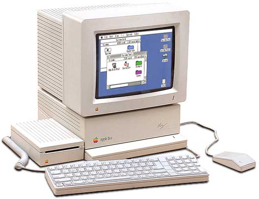
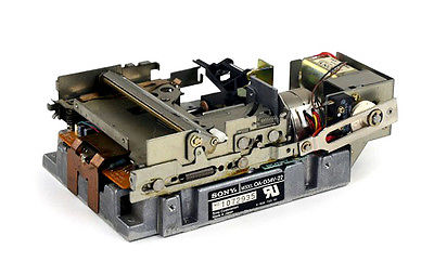
Last of the bunch is the Apple 3.5 Drive. Unlike the others, this drive functions on the Macintosh as well as on Apple II systems. It is not a SmartPort drive. How does that bit of magic work? I wish I understood it. Internally it’s the same Sony 800K mechanism that’s in the Unidisk 3.5 and in standard Macintosh floppy drives like the M0131, so the difference is only in the interface circuitry. I believe the Apple 3.5 Drive is supported on the Apple IIc+ and the IIgs, but it may also be supported on the standard model IIc – source seem to conflict on this point.
How does the computer know that an attached floppy drive is an Apple 3.5 Drive, and not a Unidisk 3.5 or other SmartPort drive, or a dumb 5.25 drive? I’m not sure, and the lack of documentation is frustrating. You can’t just plug a Macintosh floppy drive directly into a IIgs, so obviously there’s some difference in the way it identifies itself to the Apple II, but what is it? If I can find the answer, then I think the existing Floppy Emu firmware should work as-is for Apple 3.5 Drive emulation on the IIgs and IIc+.
Incidentally, if you have an Apple 3.5 Drive, you can remove its drive mechanism and substitute a Floppy Emu in its place. Combined with the 3.5 Drive’s internal daisy-chain board, this combination works today with the current firmware, on the Apple IIgs (and presumably also the IIc+) for 800K disk emulation. See Bryan Villados’ example on the Apple II Enthusiasts group.
/3.5DISK Mystery Signal
The biggest mystery at the moment is how an Apple II system can detect what type of floppy drive is connected, and this /3.5DISK signal on pin 4 seems to be part of the answer. For detecting the difference between a dumb 5.25 drive and a SmartPort Unidisk 3.5, I think /3.5DISK must be irrelevant, because the standard model Apple IIc lacks the /3.5DISK signal but can still use a Unidisk 3.5 drive. Also, SmartportCFA successfully emulates a SmartPort drive, and doesn’t even connect pin 4. My guess is the computer sends some kind of SmartPort “init” command that will fail in a predictable way on a dumb 5.25 drive. Exactly how that works will have to wait for a deeper investigation of the SmartPort protocol.
Most likely, the /3.5DISK signal is used only for detecting the Apple 3.5 Drive. If the Unidisk can be detected by a SmartPort query, then /3.5DISK is probably only for distinguishing between an Apple 3.5 and a dumb 5.25 Disk II drive. That sounds easy enough, but when I start to look at the details, I quickly get lost.
First: is /3.5DISK 0 for 3.5 inch drives and 1 for 5.25 drives, or vice-versa? Most sources refer to it as /3.5DISK or 3.5DISK*, both of which imply it’s an active low signal where 0 means it’s asserted, so 0 should mean to enable the 3.5 drive. This is also consistent with the fact that the Macintosh has pin 4 permanently tied to ground, and in order for the Apple 3.5 drive to function on a Mac, it would need to interpret the 0 volts on pin 4 as the assertion of /3.5DISK. However, this discussion from comp.sys.apple2 says it’s actually the opposite: 0 enables the 5.25 drive and 1 enables the 3.5 drive. Maybe the writer is just mistaken, but I’m not so sure.
Second, and more fundamentally: is /3.5DISK an input, or an output? If the purpose is to detect what type of drive is connected, then it should be an input. None of the documentation I’ve seen actually specifies, but from a few odd comments and schematics, I’ve inferred that it’s actually an output. As best as I can determine, then, /3.5DISK acts more like a secondary enable signal than a drive type detection signal. When /3.5DISK is asserted, then the attached Apple 3.5 drives should respond, and when it’s not asserted the dumb 5.25 drives should respond. Combined with the /ENABLE1 and /ENABLE2 signals, this would provide a way to control two drives of each type, and four drives total (not counting SmartPort). But there’s a problem with this interpretation – the dumb 5.25 drives don’t know anything about /3.5DISK. They think pin 4 is a ground connection, so they’re not going to play along nicely. Obviously I’m missing something, because this just doesn’t add up.
The comp.sys.apple2 discussion that’s linked above further confuses the issue. It refers to /3.5DISK as “an extra enable” line, but also says “The Apple 3.5 drive uses this signal (on its daisy-chain connector) to sense whether a 5.25″ drive (or SmartPort drive?) is connected at the end of the chain.” In this context where it’s used to “sense” a drive’s presence, it sounds like /3.5DISK is an input. Maybe it’s actually some kind of clever circuit that’s both an input and an output, depending on the context.
A final question: what’s the difference between the Apple 3.5 drive and a standard 800K Macintosh floppy drive? The Apple 3.5 drive works on both an Apple IIgs and a Mac – how does it accomplish this? If the answer were only related to the /3.5DISK signal, and that signal was strictly an output from the IIgs, then a Mac 800K drive ought to happily ignore that signal and still respond to the /ENABLE1 signal, and work fine on a IIgs. But that’s not what happens, so there’s a piece of the puzzle I’m missing.
Read 7 comments and join the conversationFloppy Emu “Universal” Firmware Update
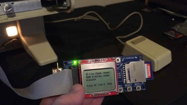
I’ve merged the Lisa floppy emulation functions into the latest Mac version firmware, to create a super universal firmware! it’s a single firmware for Floppy Emu with support for Mac and Lisa, floppy and HD20, raw disk images and Disk Copy 4.2 images. It also brings the benefits of writable DC42 disk images to the Mac. Sorry, it does not make sandwiches or wash your car, but it does nearly everything else. Press the SELECT button while the Emu is displaying version info on the LCD, you’ll enter a config menu where you can choose to operate as a hard disk, Mac floppy drive, or Lisa floppy drive. The new hd20-0.7B-F14.5 universal firmware is available now.
A few other odds and ends:
Checksums
After some discussion, I’ve altered the strategy for updating Disk Copy 4.2 checksums. I still don’t have a good solution for keeping the checksums updated when the disk image is modified, but instead of leaving the old (wrong) checksums in place, this new firmware sets the checksums to zero upon the first write to a DC42 image. Hopefully this will make it clearer for some future archivist who may encounter the modified image file, and he’ll understand the checksum was intentionally zeroed, rather than the image file being corrupted.
dc42cksm – I wrote this simple command line program to view the checksums in a Disk Copy 4.2 disk image file, and optionally to update the checksums if they’re not correct. If you ever have some burning need to copy a modified DC42 file off your SD Card, and import it back into Disk Copy 4.2 on the Mac, this tool can fix up the checksums for you. It’s a Windows command-line executable, but the source code is also included if you want to recompile it for OS X or Linux.
Blank Disks
Todd Meyer pointed out that blank 400K disks created under Lisa Office System 3.0 and 3.1 aren’t usable under Lisa Office System 2.0. The difference seems to be similar to the distinction between MFS and HFS disks on a vintage Macintosh system, except I don’t think the Mac ever used two different filesystems for the same sized disk. Thanks to Todd for providing a working LOS 2.0 blank disk image, which I’ve included with the lisa-emu-1.0S7-F11 firmware (below), and for the femu-on-Lisa photo that appears above.
A Spare Firmware
In case any problems are discovered with the new universal firmware hd20-0.7B, I’m also releasing an updated version of the Lisa-specific firmware, lisa-emu-1.0S7-F11. This is identical to the 1.0S6 Lisa firmware that I released yesterday, except that the checksum in the DC42 image file will be set to zero upon the first write to the disk.
???
The Lisa computer is a strange beast. It was the first mainstream home computer to feature a GUI instead of a text-based interface. It’s been interesting working with the Lisa while I developed the new floppy firmware, and for a time I thought maybe I’d like to get a Lisa system of my own when the time comes to return this borrowed machine. But the Lisa never really grew on me, and I can’t exactly say I’ll miss it when I need to give it back.
Running the Macintosh OS under MacWorks isn’t too bad, except that the machine has twice the bulk and weight of a contemporary Mac system. It’s just… unwieldy. That’s not meant as a dig against the Lisa – pretty much all computers of that era were unwieldy by today’s standards – but it’s impressive how much slimmer Apple was able to make the Mac 128K just a year after the Lisa, using most of the same technology except for the internal hard drive.
From the viewpoint of someone in 2015, the native Lisa OS (Lisa Office System) is truly baffling, ugly, and awkward. I’m not surprised Apple had such trouble selling Lisa systems before MacWorks came along. As the first real GUI computer, it’s no wonder Apple didn’t nail it 100% on the first attempt, so I don’t fault the Lisa or its designers for that. It’s fascinating to see this example of an early GUI, in contrast with the continuing improvements that appeared later in the Mac and other GUI systems.
Read 6 comments and join the conversationLisa Native Floppy Emulation
Lisa floppy drive emulation with Floppy Emu is a success! Begone, evil rotational disk drives, with your failure-prone gummed-up mechanisms. The age of SD card Lisa floppy emulation is here!
After a lot of tinkering, it’s now working on both the Lisa 2/5 and 2/10, and for both Lisa-format and Mac-format disks. I’m able to boot the Lisa from the emulated floppy drive, and use it to install Lisa Office System and other apps to the HD, and copy apps and data files from the Lisa HD to the emulated floppy drive. It also works for Mac-format disks, when running the Lisa under Macworks.
The final hurdle was realizing that the custom adapter I’d built to simultaneously connect a 400K floppy drive and a Floppy Emu was causing problems. After getting rid of the adapter and connecting the Emu directly to the Lisa, in place of the normal floppy drive, it’s now working perfectly.
Disk Copy 4.2 Format
From the previous Lisa firmware that I described in an earlier post, the last big piece of the puzzle was adding support for “tags”. On a Lisa floppy disk, a sector consists of 512 bytes of data and 12 bytes of tags. Raw disk image files don’t save the tag info – they’re just a byte-by-byte copy of the 512 data bytes from each sector. So in order to correctly emulate Lisa-native disks, it was necessary to use a disk image format that preserves tags: Disk Copy 4.2 images, the format I love to hate.
Floppy Emu already supported DC42 format image files for use with the Macintosh, but they were treated as read-only disks by the emulator firmware. The problem with tagged DC42 images is that the logical sector data isn’t aligned in the image file, nor in the FAT32 filesystem of the SD Card, and the sector tags are stored separately from the sector data. So to load a single sector of the emulated floppy (512 bytes data plus 12 bytes tags), it’s necessary to load three or sometimes four 512 byte sectors from the SD card, depending how the data and tags for that particular sector are aligned. It’s a pain in the butt.
Writing DC42 images is more complicated still, which is why previous firmware treated DC42 images as read-only. To perform the unaligned writes, the firmware must read a sector from the SD card, modify part of it, then write the modified version back. Again, this can involve three or four SD card sectors in order to write a single emulated floppy sector. SD cards really don’t like this pattern of read-write-read-write for single random-access sectors, so performance suffers a bit. But the new firmware code does its job, and writing to DC42 disk image files is now possible.
Checksums
The last unsolved item is DC42 file checksums. A DC42 image file contains a 32-bit checksum of all the data, and a separate 32-bit checksum of all the tags. If you attempt to load an image file with invalid checksums in Disk Copy 4.2, it will refuse to open it. Floppy Emu doesn’t care about the checksums, but there can be a problem if you copy a modified DC42 image file off your SD card, and try to use it with Disk Copy 4.2 or another utility that does care about checksums.
What’s the best way to make sure the checksums are kept up to date, when the DC42 image file is modified? Now that I know the checksum algorithm, I can recompute the checksum easily enough, but when should I do it?
- It’s impractical to recompute and save a whole-disk checksum, every time any sector is modified.
- I can update the checksum when the disk image is ejected, but that’s dangerous because ejection is very often a prelude to auto power-off a moment later. It takes about 2 seconds to recompute the checksum for a 400K disk, and 4 seconds for an 800K disk. Usually the time between ejection and shutdown is less than that. If the Floppy Emu loses power while it’s writing the new checksum value, the SD card could become corrupted.
- I might recompute the checksum when the disk image is inserted, but that’s unintuitive. Re-insert the disk image, in order to fix its checksums? And for systems like the Mac that write the last mount time whenever a disk is inserted, the checksum would still always be wrong.
- I might add some new Floppy Emu menu option or feature to recompute the checksum on demand. But that’s a strange special case I’d like to avoid, and doesn’t feel like the right solution.
- I could do nothing, and let people fix up the checksums with an offline tool if they ever need to copy them off the SD card and reimport them to Disk Copy 4.2. This is my solution for now.
Try It
If you’ve got a Lisa and a Floppy Emu, you can try the new firmware yourself. I’ve named this firmware version lisa-emu-1.0S6-F11, and it contains all the changes needed to emulate Lisa-format and Macintosh-format floppies on the Lisa computer, and to boot a Lisa from the Floppy Emu board. 1.0S6-F11 contains some changes that aren’t compatible with early Macintosh models, so while you won’t hurt anything by trying it on a Mac system, it may not work. For best results, use the normal Mac firmware for Floppy Emu with Macintosh computers, and use 1.0S6-F11 only when working with a Lisa system.
Read 9 comments and join the conversationLisa Floppy Emu, Looking Good
I’ve been crawling slowly closer to a working floppy emulator for the Apple Lisa, using my existing Floppy Emu hardware. I’ve now got something that’s broadly usable for emulation of Macintosh disks on the Lisa 2/10, when running under the Macworks environment, though it’s still far from perfect. The next step will be emulation of native Lisa floppy disks, so the computer can boot from the Emu and use it from within the Lisa Office System. Things are looking promising!
Setup
So far, most of the effort has gone into getting my borrowed Lisa to the point where I can actually run floppy tests. Initially it seemed no setup would be necessary – just plug the Floppy Emu into the Lisa, and see if it works – but reality has proven different:
- Create a hacked version of Basic Lisa Utility that doesn’t need the M key (my M key is broken)
- Buy/build a Lisa-to-PC serial cable to capture the BLU log data
- Build a custom floppy drive A/B switch, so I can connect a real 400K drive and a Floppy Emu at the same time
- Rewrite my floppy tester utility program in Think C 5.0, to avoid a mysterious crash bug on the Lisa
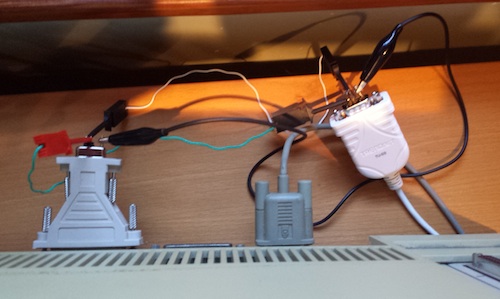
In order to capture the log data from BLU, I needed a serial connection to the Lisa. I ordered this USB-to-DB9 serial adapter, along with a separate DB9-to-DB25 adapter, and waited impatiently for them to arrive. After receiving the adapter, I connected the Lisa up to my Windows 7 PC, and of course it didn’t work. The link appeared totally dead, and nothing I did on one computer was seen by the other.
I’d been corresponding by email with a few Lisa experts, and one of them pointed out what I should have realized about the serial connection: I needed a null modem connection, not a straight serial connection. Serial cables have separate TXD and RXD lines for transmit and receive, and in normal usage the computer will transmit on TXD and receive on RXD, while the peripheral will receive on TXD and transmit on RXD. But with my Lisa-to-Windows hookup, both ends thought they were “the computer”, so both were trying to transmit on TXD. Argh!
I looked into buying a null modem adapter, which would also have required getting a gender changer too. But I got impatient, and finally just built my own solution out of some jumper wires to swap TXD and RXD. It works.
Emulation
The best diagnostic tool I’ve found is the floppy tester function of BLU, which generates sector-by-sector debug info. There are some categories of disk problems that BLU doesn’t report, such as drive speed adjustment problems and synchronization problems, but it’s still the most powerful tool for the job.
I’ve been corresponding with two people who own Lisas and Floppy Emus, and the three of us have been testing various Emu firmware versions and comparing the test results. With the latest “Lisa Emu” firmware, the emulation doesn’t work at all on a Lisa 2/5, but does work on a 2/10. These two Lisa models have completely different floppy controller hardware that should be functionally equivalent, but some hidden difference is clearly important here. More on that later.
On the Lisa 2/10, we discovered that the Emu firmware routine that generates the 10-bit bitslip marker wasn’t working. The bitslip marker is used by the floppy controller to find the correct byte-to-byte framing in the floppy data serial bitstream. After fixing that, the emulation started worked on the Lisa, but very slowly. There were clearly still lots of floppy errors happening, slowing down the I/O, even though it eventually succeeded.
Disk Rotation Speed
When testing with BLU, doing a sequential read of all the sectors on the disk, it appeared to freeze for about 15 seconds before reading the first sector on each track. BLU didn’t report any errors, but there was clearly something wrong. After some discussion with my remote Lisa testing partners, we began to suspect this was a problem with the simulated rotation speed of the emulated disk, and we were right.
With an Apple 400K floppy disk drive, the drive spins at different speeds depending on which track is being accessed. The disk is divided into five speed zones, with five different rotational speeds ranging from 394 to 590 RPM. The computer directly controls the drive’s rotational speed by modulating a signal called PWM, and the drive indicates its current speed with a signal called TACH. So the computer sets PWM, then reads TACH and verifies that the desired rotational speed has been reached. If the verification fails, a Macintosh will report error -79: “can’t correctly adjust disk speed”. But what will a Lisa do?
The Floppy Emu doesn’t actually use the PWM signal, but instead it sets the TACH value directly, based upon which track is accessed by the computer. I tried modifying the Emu firmware to generate an obviously wrong TACH, and the behavior on the Lisa was unchanged. It still wasn’t reporting any errors, but the 15 second pause at the start of each track was still there. This told me that the TACH value was probably wrong all along, and that the Lisa was waiting about 15 seconds on each track for the TACH speed to become correct, then giving up and attempting the I/O anyway.
I blindly experimented with different formulas for TACH. Make it faster? Slower? Change the speed by a percentage, or by a constant offset? After lots of trial and error, I found that scaling TACH by 2.5% across the board made all the 15 second pauses disappear. So in effect, the Emu is reporting that the drive’s rotational speed is 2.5% faster than the spec. Why is this necessary? I honestly have no idea. The revised formula is almost certainly still wrong, but it seems to work well enough for now.
Inter-Sector Gap and Interleave
The sectors on a normal Macintosh disk are interleaved 2:1, with a short gap of dead space between sectors. Conceptually it looks something like this timeline view:
0000000000.6666666666.1111111111.7777777777.2222222222.8888888888 etc.
The 2:1 interleave means sector 6 follows sector 0, then come sectors 1, 7, 2, 8, 3, etc. The gap between each sector is about 10% the duration of the sector itself. The purpose of the interleave is to get the fastest possible I/O speeds when doing sequential reads of many contiguous sectors, allowing for some amount of CPU processing time after reading each sector that wouldn’t be possible with a 1:1 interleave.
For a sequential read of many sectors and a correctly tuned interleave, after locating the first sector on a track, the floppy controller should see zero unwanted sectors go by before the next desired sector appears. But I discovered that for BLU’s sequential read test, the floppy controller was almost always seeing 11 unwanted sectors before the desired sector appeared. There are 12 sectors per track on this region of the floppy, so 11 unwanted sectors meant the Lisa was just missing the desired sector, and had to wait for an entire rotation of the simulated disk (11 more sectors) before the desired sector rolled around again. In short, this meant it needed a higher interleave than 2:1. But that couldn’t be right, because real Mac disks are interleaved 2:1, and the Lisa under Macworks can read them without problems.
I wasted a lot of time experimenting with different interleave values, and different gap sizes between the sectors. Eventually I found a combination that led to zero unwanted sectors after the first sector of the track, but it required a huge and unrealistic inter-sector gap size. And while it made the BLU floppy test results look better, it actually performed worse in real-world tests, copying files under Macworks.
Finally I had the idea to repeat the BLU floppy test with a real floppy disk and drive, and observed the same 11 unwanted sectors before the desired sector. Aha! This told me the issue was actually with the BLU test, and not with the Floppy Emu firmware. BLU must be doing a non-trivial amount of CPU computation or other I/O after each sector, more than is normally performed by the OS during a sequential read, so that by the time it’s ready for the next sector, the desired sector has already rotated past. I reverted all of my changes, and put the inter-sector gap size back where it was originally. The BLU results got worse again, but real-world performance under Macworks improved noticeably.
Recalibrations?
One more mystery remains unsolved. In all of my BLU tests, the reported value for recalibrations (Rcl) is always 4C. For one of the other testers, it’s always 02. I’m not sure yet what the third tester is seeing for Rcl. The BLU manual appendix D says Rcl is “recalibrations remaining”, and that an operation normally starts with 1 recalibration remaining and counts down from there – so both 4C and 02 are anomalous. What’s the significance of this? It needs more investigation.
Real-World Tests
Using a Lisa 2/10 system, I booted Macworks XL from the Lisa’s hard drive. By holding down the left option key, I told Macworks to initialize the Macintosh environment, but wait for a floppy disk to actually boot the Mac OS. Using a real 400K floppy drive and disk, I booted System 3.2, measuring the time from disk insertion to ready desktop at 37 seconds. Then I repeated the same experiment with Floppy Emu and a disk image of System 3.2, and measured it also at 37 seconds. So it works! No more mysterious slowdowns: Floppy Emu on the Lisa performs at the same speed as a real floppy.
As a second test, I booted Macworks from the Lisa’s hard drive, then used Floppy Emu to insert a 400K disk image containing MacPaint and MacWrite. The disk image appeared on the desktop within a few seconds of inserting it, and copying MacPaint from the Emu to the Lisa’s HD only took a few seconds more. I was also able to copy files from the HD back to the emulated floppy disk without problems. Given what I’m seeing in these tests, the current firmware should provide a fully usable and full-speed floppy emulation for the Lisa under the Macworks environment.
Try It
If you’ve got a Lisa and a Floppy Emu, you can try the new firmware yourself. I’ve named this firmware version lisa-emu-1.0S3-F11, and it contains all the fixes and adjustments described above in order to make Macintosh disk emulation work on the Lisa in the Macworks environment. Native Lisa floppy emulation still isn’t implemented, but I hope to tackle that soon.
Be the first to comment!Floppy Emu AVRGCC Mystery Behavior
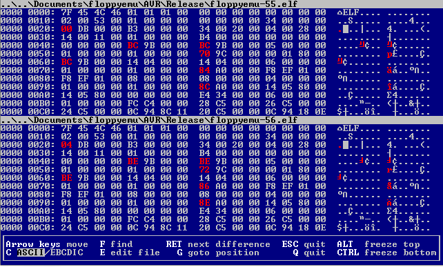
For a while I’ve been struggling with occasional mystery bugs when making changes to the Floppy Emu AVR microcontroller firmware. I’ll make some seemingly innocuous code changes, and completely unrelated things will break. Frequently I’ll change something in a menu or other user-facing code, and suddenly the Emu will lose the ability to read the SD card, and insist there’s no card present. Needless to say, this makes development a real pain in the butt.
Today I found a perfect example of this behavior, where changing the max loop count in some code that’s not even executed would cause the Emu to lose access to the SD card. Buried in the code that simulates reading a floppy disk image is this:
#define INTER_SECTOR_GAP_SIZE 55

// lots of stuff omitted

for (uint16_t i=0; i<INTER_SECTOR_GAP_SIZE; i++)

{

  SendByteAndCheckRestart(0xFF);

}
What I found is that if I changed 55 to 56 or 65 or pretty much any other number, the Emu would suddenly become unable to read the SD card. What’s strange is that this for loop isn’t even executed during Emu startup, where the SD problem occurs. And just changing a single constant from 55 to 56 shouldn’t change the size or location of the compiled code, or anything else that might reveal previously hidden memory-related bugs. But it was extremely reliable: 55 always worked fine, 56 could never read the SD card.
Determined to find an explanation, I grabbed the binary diff tool VBinDiff and used it to compare the two compiled .hex files. I fully expected the files to be identical, save for a single byte that was 0x47 in one version and 0x48 in another version. But I was stunned to find the two files differ in hundreds of places! There are at least a hundred single-byte differences, as well as whole blocks that are different between the two. Thinking maybe I was getting different compile results from one compile to the next, due to a compiled-in timestamp or something weird, I tried compiling the same source code twice and comparing the results. They were identical. But if I changed the loop count, I got a hugely different result. And somehow that result was causing an SD card problem.
At the moment I don’t have any explanation for this, except maybe for some kind of compiler optimization that kicks in after 55 something-or-others. If you’re curious, you can compare the two .hex files yourself: floppyemu-55.hex, floppyemu-56.hex. The hex files show exactly what will be programmed into the ATMEGA1284’s flash memory.
Read 15 comments and join the conversation