

Swag
The BMOW stickers arrived today, and they came out perfectly! Mmm, one thousand delicious 3×3 squares of BMOW goodness for the Maker Faire.
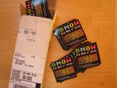
I only wish I’d made them larger. 3×3 doesn’t feel as big as I’d imagined it would. Still, they’ll make a great give-away for the Faire.
Totally unrelated to BMOW, but the mailman also brought me my new Vibram Five Fingers running shoes today:

BMOW Road Trip
I took the BMOW 1 hardware on the road this week. A few of the people I work with have been polite enough to feign interest in the project, and I’d repeatedly promised to bring it to work for a demo when it was ready. On Monday I lugged the whole setup to the office, and left it there for two days, showing it off to whomever came by and asked about it. I wish I’d taken some photos. It turned out to be a great dry run of what I’m likely to encounter at the Maker Faire next month, and I learned some helpful things about the demo and myself in the process.
- From an audience of very technical people, it basically broke into two groups. Most asked one or two general questions, and left in less than a minute. A few stayed for 15 minutes or more. Some of this was detailed BMOW questions, and some was stories of their own about hardware “back in the good old days”.
- I had trouble summarizing what the project was in a couple of sentences, and really need to work on this. Many people didn’t seem to grasp what it meant to build a custom CPU, although they got the general idea.
- I found that I actually got bored of talking about the machine after the fifth or sixth repeat of the same little talk. That doesn’t bode well for the 18 hours of the Maker Faire. It actually surprised me– I thought I’d never get tired of talking about my projects.
- Everyone wanted to see the wiry mess, which is unsurprising given the project’s name. Sadly, all the wires are hidden on the underside of the board when it’s mounted in its case. For the Maker Faire, I’ll definitely have plenty of photos on hand of the wiring side, and a sample wire-wrap board. I wish I could think of a safe and easy way to let people see the wire side of the BMOW main board when it’s on display.
- Quite a few people said they’d expected it to be bigger. I’m not sure how to respond to that.
- I may need to add some more built-in demos. There are 12, but they basically break down to listen to some music, look at a picture, play chess, or run BASIC. Nobody got further in BASIC than: 10 PRINT “HELLO”, 20 GOTO 10.
- Stability was pretty good. Over two days, constantly running in a demo loop, it only crashed a couple of times. There were a few very bizarre bugs that disappeared after a reset, though, like the “C” key stopping working.
- A few people joked about “accidentally” spilling coffee onto the board. With a few thousand people at the Maker Faire, somebody probably will spill something on it. I’m still unsure what the best way of protecting it is. I’ll probably need some kind of transparent protective cover.
In another month, I’ll go through the same drill again at the Faire, but with better props and a much larger audience.
Read 8 comments and join the conversationConstruction Notes
3D Graphics Thingy should teach me plenty about both digital design theory and practice. It’s pretty clear what the theory part entails: defining the architecture and its implementation. The practice part is less obvious, but probably more important to the hobbyist: it’s all the little skills and bits of knowledge required to translate a schematic into a physical piece of hardware that actually works. Before BMOW 1, for example, I didn’t know a thing about wire-wrapping, and my soldering skills were almost non-existent. 3DGT will provide an opportunity to grow my construction skills even further.

It’s almost certain that 3DGT will incorporate plenty of surface mount chips, since most of the higher-level digital building blocks I’m looking at are only available in SMD form. In contrast, BMOW was built entirely from through-hole DIP parts. Using SMD parts means soldering will be more of a challenge, thanks to the smaller, more closely-spaced SMD pins and the lack of anything to hold the chip in place while it’s soldered. I’ve read numerous guides that all claim it’s possible to hand-solder many types of SMD parts, if you have the right tools and a steady hand, but there’s no doubt it will be a challenge. Of course, protoboarding anything with SMD parts is out of the question, unless using SMD to DIP adapter boards and soldering to those.
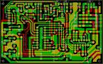
SMD parts mean no wire-wrapping either. Creating a custom PCB looks like the only way to go here, and since that’s something I’ve been itching to do for a while anyway, I’m excited by the challenge. There’s plenty of free and low-cost software for designing custom PCBs, and low-volume manufacturing services that will fabricate a few custom boards for $50-$100, depending on the size and other variables. So instead of having a big mess o’ wires, I’ll have a… big mess o’ traces? It doesn’t bring quite the same image to mind, does it?

I’ve been looking for an excuse to tinker with CPLDs or their bigger cousins FPGAs, and this project should provide it. BMOW ended up using twenty-six 22v10 GALs, which are very simple programmable logic elements. I’m guessing the logic needs for 3DGT will be substantially greater, so I’ll be stepping up to CPLDs or FPGAs to reduce chip count and power consumption.
As a side note, there’s a decent chance that most of the “interesting” bits of this project will end up being entirely within CPLDs or FPGAs, and not exist as externally distinct components at all. I’m OK with that. The only requirement I’m imposing on myself is that the CPU must be distinct from the graphics coprocessor, and the graphics coprocessor must be entirely of my own design. However that’s easiest to realize in hardware is the direction I’ll go.

3DGT will use a commercial CPU, albeit probably an old-school one like something from the Motorola (now Freescale) 68000 series, MIPS, or ARM. It will probably be in the 25 to 50 MHz range. Anything faster than that, and I’ll begin to doubt that this novice can successfully design a custom PCB that avoids all the noise problems that can plague high-speed boards. I have a certain fondness for the 68000 series, due to the nicely-designed instruction set. The Playstation used a MIPS R3000, which I need to learn more about. I also have a vague feeling that certain ARM processors might play well here, but again that’s something I don’t know much about yet.
There’s a chance that 3DGT will actually incorporate multiple CPUs or microcontrollers, but only one will be “the CPU” where the main program runs. I’m speculating that it may work well to use an additional CPU or microcontroller somewhere within the graphics coprocessor, running a simple fixed program to assist in graphics generation. I’ll write more on that later when I discuss the architecture.
The VGA output will probably make use of a modern triple 8-bit video DAC, instead of the old VGA palette chip I scavenged from a video card for BMOW. That will allow for direct color pixels, instead of pixels being treated as indices into a 256 entry palette. Direct color pixels are required for interpolating color data across the face of a triangle, but more on that later.
I’d like to incorporate an SD card reader into the design. Trying to fit everything into 512K Flash ROM for BMOW was a pain.
Of course there will be a joystick port too. This is a video game setup, after all. Hopefully I can buy some control pads from an older game console like the Playstation, and reverse-engineer the connector pinout.
The rest of the parts should be similar to BMOW: a few static RAMs, Flash ROM, keyboard interface, USB, and audio.
Add that all together, and a vision of 3D Graphics Thingy takes shape: it looks like a custom PCB with 10-20 parts, employing an off-the-shelf CPU, FPGAs, and other large scale integration parts. It has inputs for keyboard, joystick, and USB, and outputs for VGA and audio. Physically, it’s probably about half the size of BMOW. If you put the whole thing in a nice case, someone might even mistake it for a professional piece of hardware!

I expect it will take quite a while to get familiar with CPLDs and FPGAs, and most of the early project challenges will probably relate to this. The investigations I’ve done so far have answered some questions, but raised many more. I’m also concerned about the cost, as some of the higher-end FPGAs appear to be extremely expensive. Capacity is variously measured in flip-flops, macrocells, or just “gates”. I’m not sure how to relate that to anything concrete, so I don’t even know what order of magnitude of FPGA complexity I should be considering.
The biggest question I have right now is how to physically incorporate an FPGA. All the hobbyist-oriented packages I’ve seen are FPGA development kits, which are complete boards containing the FPGA, some RAM and ROM, switches, LEDs, JTAG interface, and a bunch of other stuff. I assume I don’t want to incorporate an entire development board into the 3DGT design, or do I? I haven’t even seen individual loose FPGAs advertised for sale anywhere, and if I found one, I’m not sure what I’d need to do to incorporate it into my PCB. I don’t even know how you program one, once it’s soldered onto the board. In-circuit programming header, I guess?
I have a Xilinx XC9572 CPLD in a breakout board to play with that I acquired a while back from another hobbyist, but I’ve never used it. The JTAG interface uses a parallel port connector, and my PC doesn’t have a parallel port. At any rate, I think the XC9572 is too simple for my needs, and is roughly the equivalent of seven 22v10 GALs. The only thing in its favor is that it’s in a PLCC package, which fits in a socket with through-hole pins. That makes it easier to solder, and possible to reuse the same CPLD in different prototype boards by transferring it between sockets.
Time to do some more research!
Read 11 comments and join the conversation3D Graphics Thingy
OK, it’s a year and a half later, and once again I’m staring at a blank sheet of paper. It’s time to start a new project. My very inspired name for this effort is 3D Graphics Thingy.
When I’m not moonlighting as an electronics hacker, I get paid to be a video game developer. I write software to push around triangles and pixels and create 3D animated scenes. Military simulations were my introduction to the field, using big-box SGI hardware. For many years I was a developer at Electronic Arts, and was lead programmer on some high-profile game titles like Tiger Woods Golf. I’m currently deep into development of a new fantasy MMO game.
Working in the game industry has given me an appreciation for hardware that gets lots of pretty images on the screen, fast. I’ve done 3D graphics work on the PC with Direct3D, and on consoles like the Playstation, PS2, Xbox, and GameCube. While none of it involved working directly with hardware, the software interfaces encouraged intimacy with the hardware, especially on the consoles (and even more so on the PS2). In order to wring the best possible performance from those systems, it was necessary to understand how the hardware worked at a fairly detailed level.

Prior to 1995 or so, most games were 2-dimensional, and most game hardware was designed with 2D games in mind. Sprites and parallax scrolling were the mainstays, and titles like Sonic the Hedgehog were state of the art. Typically, a video frame buffer was filled with a background image, which changed infrequently. Hardware-accelerated sprites were overlaid onto this background, for player characters, monsters, bullets, and so on. The number and size of sprites were limited. For efficiency, a dirty rectangle technique was used to redraw only those parts of the screen that had changed since the last video frame. Hardware generally wasn’t powerful enough to draw the entire screen with a new image every frame, while still maintaining a frame rate fast enough for motion to appear smooth (typically 30+ frames per second).

3D began to creep into the picture in the early 1990’s, with hardware like the Super Nintendo’s Super FX chip, but it was the 1995 introduction of the Playstation 1 that really shook things up. I remember playing the original Ridge Racer and being absolutely stunned by the fluid 3D graphics. This was possible thanks to the PS1’s hardware, which was designed from the ground-up for the task of fast 3D image generation. Every frame, the frame buffer was completely erased, and an entire scene of 3D objects was drawn. Each object was typically constructed from dozens or hundreds of individual triangles. No sprites, no scrolling, no dirty rectangles. It was a completely different way of making a video game, and a completely different approach to the hardware.
The PS1 and its conceptual descendants (including modern PCs) draw a fairly sharp line between general-purpose computing tasks, and the work involved in 3D graphics generation. General tasks are performed on a standard CPU like a 68000, MIPS, or Pentium. For a game, that might include player movement, collision detection, and keeping score. It would also include determining what things should be drawn on screen, and where. The actual task of drawing is performed by one or more specialized pieces of hardware that are collectively referred to as a graphics coprocessor, GPU, or just graphics card. In your PC this might be another chip on your motherboard, or an add-in card from nVidia or ATI.

So let’s pretend it’s 1992, I’m a hardware engineer, and I’m drawing up plans for what will eventually become the Playstation. Clearly some kind of specialized graphics coprocessor will be needed, but no such thing exists, aside from a few small and expensive niche markets. So how should it work? What factors should be emphasized in the design? What tradeoffs must be made? Will it even be possible to design something powerful enough, cheaply enough, using available technology?
3D Graphics Thingy will be my answer to these questions. Using mid-1990’s technology, I plan to build a graphics coprocessor capable of generating real-time 3D graphics, and match it with an off-the-shelf CPU to build a custom single-board computer, optimized for the task of gaming graphics. In short, I’m building my own video game console.
I’ll post more soon on the specific functional requirements for 3D Graphics Thingy, the kinds of technologies I expect to use, and my initial thoughts on the system architecture.
Read 8 comments and join the conversationDone?
I think it’s done. This evening I went to work a bit more on BMOW, and realized… there’s nothing left to do. The last little bit was finished this weekend, and involved creating a self-running demo loop of all the BMOW programs in ROM. Now it still boots to the same power-up screen as before, but after 30 seconds of idle time, it’ll start looping through a sequence of 10 different audio, video, and interactive demos. It can be interrupted at any time, and if somebody starts playing with the interactive demos (Microchess and BASIC), it will let them play as long as they wish, continuing the demo loop after another suitable idle period.
The only other bit of work I can conceive of is constructing a clear replacement cover for the BMOW case. The current case is solid steel and hides everything away inside, so a clear cover would be a nice way of showing things off while still keeping them protected. I looked a bit into some online custom plastics manufacturing options at Big Blue Saw and Polou, but they’re both limited to 2D parts. A custom replacement cover would need a top, sides, back, and guide rails on the inside, and I’m not too excited about trying to glue or screw together a 3D part from a bunch of 2D parts. Unless I come up with some great brain wave that can simplify it, I’ll probably skip this idea, and just leave the cover open when I want to show the machine off.
The timing of the Maker Faire is a lucky coincidence, giving me an excuse to polish things up nicely and have a little celebration before going on to a new project. I’ve spent more time in the past week planning for my Faire exhibit than on BMOW itself. Originally I’d planned to have some business cards printed up that summarize what the project is about, but then I asked myself why I’d want boring business cards when I could have stickers! I think I have an irrational fondness for stickers. I designed a custom 3×3 inch BMOW sticker and ordered 1000 of them from UPrinting. Take a peek at the sticker proof to see the design. Come to the Maker Faire and I’ll give you one!
I’ve still got a few more projects left to prepare for the Faire, like T-shirts, a Powerpoint presentation, notebooks of schematics and construction photos, and general booth equipment (lights, cloths, cords, monitors, wire wrap samples, and other sundries). That should keep me busy for a while.
I also updated all my online documentation recently, including quite a bit of new content, and put it all on a new Downloads page. It includes all the schematics, software, wire lists, Verilog models, PC tools, and anything else I could think of.
As one door closes, another opens, and I’ve begun thinking harder about my next project. One practical question I’m unsure how to answer is where I should write about it. I’ve really enjoyed logging my progress with BMOW here, and the great comments and dicussions it’s led to with like-minded people all over the world. I definitely want to keep that going for my next project, but is this the right place to do it? Right there at the top of the page it says “Big Mess o’ Wires”. Do I start a new site? Do I keep adding to this site, even though newer entries will be unrelated to BMOW? If so, how will future visitors understand what’s going on, or realize that there even was a machine that came before the new one?
My current thinking is to redefine “Big Mess o’ Wires” as referring generically to any electronics project of mine, since they’re all big messes of wires in one way or another. Then retroactively rename BMOW to BMOW I or BMOW Classic or something stupid, and turn this site into more of a catalog of various projects, including BMOW I. It’s also probably about time to get a real URL for this thing, instead of hanging off my content-free personal web site. Sadly, www.bmow.com is already taken (curse you, Broward Meals on Wheels!). Other options like www.bigmessowires.com seem a little verbose, and I know from my site statistics that most visitors incorrectly insert the “f” in “of” when doing a search. Maybe a .net, .org, or .info domain? Or maybe it’s fine just the way it is.
Read 4 comments and join the conversationMaker Faire
 ZOMG!!! I’m exhibiting at the Maker Faire! It’s billed as “the world’s largest DIY festival”, and is happening in the San Francisco Bay Area May 30-31. If you’re anywhere remotely nearby, make a trip to come see BMOW and the other exhibits! I attended last year’s faire, and the caliber of the exhibits was excellent. Everything was fascinating and amazing, so I’m not sure BMOW will measure up to the rest. But they accepted my application, so now they’re stuck with me. Heehee!
Thanks to Bill Buzbee for pointing me to the late-entry application. (Bill and the Magic-1 will be there this year too.) The application process was surprisingly simple: just a few words about myself, my project, and some links to photos, videos, and this site. I just got a response back today, letting me know I’d been accepted. I’m wondering about the brevity of the application: I’m not sure how they really know that the projects will be any good, or of any interest to the public. Yet while some of last year’s exhibits were better than others, I didn’t see anything that struck me as boring or lame.
I’m thrilled and excited, but I’m also pretty nervous. Besides furnishing a table, chairs, and a power outlet, the faire doesn’t provide me with any other support. I’m not sure what I’ll need to make an interesting booth, but I don’t think simply having BMOW there on a table will be enough. For one thing, if you have no idea what you’re looking at, it just looks like a bunch of crap in an X-terminal case that someone drilled a hole in.
Here’s what I’m thinking:
- A big BMOW sign or banner. Maybe scrounge up an old dot-matrix printer and make a BMOW banner with Print Shop. Or a piece of posterboard, with a pseudo-dot-matrix BMOW logo constructed from colored squares cut from construction paper.
- A second PC with a looping powerpoint presentation, outlining the highlights of the project, with photos of the wire wrapping.
- A third PC for demonstrating the simulator, microcode compiler, and other custom tools, and for downloading data to BMOW via USB.
- Printouts of the schematics and all the other technical documents in a big binder, for the truly curious.
- A continuously-running, interruptable demo loop for BMOW.
- A clear plastic or glass cover for the hardware, to protect my year and a half’s work from overly-curious finger poking.
- Maybe print up some info/business cards with the logo, summary, this site’s address, my name, and so forth. A number of exhibitors did that least year, and I thought it was a nice touch.
San Mateo fairgrounds, here I come!
Read 1 comment and join the conversation