Short Circuit Current Experiments

A couple of weeks ago I shared some thoughts about an automated tester for Yellowstone boards, including how to test for short circuits. One of the questions that grew out of the resulting discussion was whether short circuits could only be detected by functional test failures (test results don’t match expected results) or if they could also be directly detected by measuring the supply current. A second question was how large the short circuit currents would typically be. I’ve recently done some tests to help answer these questions.
There are several different kinds of shorts that we need to think about:
- shorts between power supplies, where short circuit current flows whenever the power is on
- shorts between a signal and a power supply, where short circuit current only flows for certain signal values
- shorts between two signals, where short circuit current only flows for certain pairs of signal values
- shorts where the current source comes from the device being tested
- shorts where the current source comes from the equipment that’s connected to the device
Most of Yellowstone’s external IOs pass through 74LVC245 buffers. All of the tester’s IOs will pass through MCP23S17 port expanders. So I intentionally short-circuited some samples of both chips, alone and then together, to see what would happen. Here’s what I found.
- 74LVC245 with a 3.3V supply, and one logical high output short-circuited to ground: 70 mA short-circuit current
- 74LVC245 with one logical low output short-circuited to 3.3V: 110 mA
- MCP23S17 with a 5V supply, and one logical high output short-circuited to ground: 30 mA short-circuit current
- MCP23S17 with one logical low output short-circuited to 5V: 50 mA
- 74LVC245 logical high output short-circuited to MCP23S17 logical low output: 50 mA
- 74LVC245 logical low output short-circuited to MCP23S17 logical high output: 30 mA
These currents are all large enough that it should be possible to reliably measure and detect them as deviations from the normal supply current (expected to be something in the range of 100 to 200 mA). So is this a good approach? Will it work? I’m going to try it and see, and if it’s successful then the tester will be that much more useful. If it’s not successful, I won’t have lost anything but some time and a few dollars worth of parts.
Why do this at all? Isn’t functional testing enough, with the assumption that any short circuit will cause a test failure somewhere? I say… maybe. In a perfect world, any short circuit would result in a functional test failure, but I don’t live in a perfect world. If I can do something to help detect shorts that functional tests missed, or that don’t result in test failures 100 percent of the time, I think that’s a good thing.
For how long do I need to measure the current? If the tester changes some IO values, waits a microsecond, and then measures the new supply current, is that enough? Or will capacitors on the voltage supplies smooth out the current from short circuits, so that microsecond-level measurements aren’t useful and I need to wait milliseconds or longer to get useful data? I’ll just have to try it and see.
If I measure the current, which current should I be measuring? I’m not quite sure. It might seem that I should measure the 5V supply current for the Yellowstone board (the device being tested). That would catch problems where there’s a short circuit between two elements on the Yellowstone board, whether they’re signals or supplies. It would also catch problems where a Yellowstone input signal was shorted to 3.3V or 5V, creating short-circuit currents whenever the connected equipment tries to drive a logical low to the input. But it wouldn’t catch problems where a Yellowstone input was shorted to ground.
In a case like that, short circuit current would flow whenever the connected equipment tries to drive a logical high value to the input. But since the current would be coming from the connected equipment, and not the Yellowstone board, measuring the Yellowstone supply current wouldn’t help. Maybe this is a rare enough case that I shouldn’t worry about measuring these currents, and I can just assume any such problems will be caught by a functional test.
Read 1 comment and join the conversationADB-USB Wombat Firmware 0.3.7
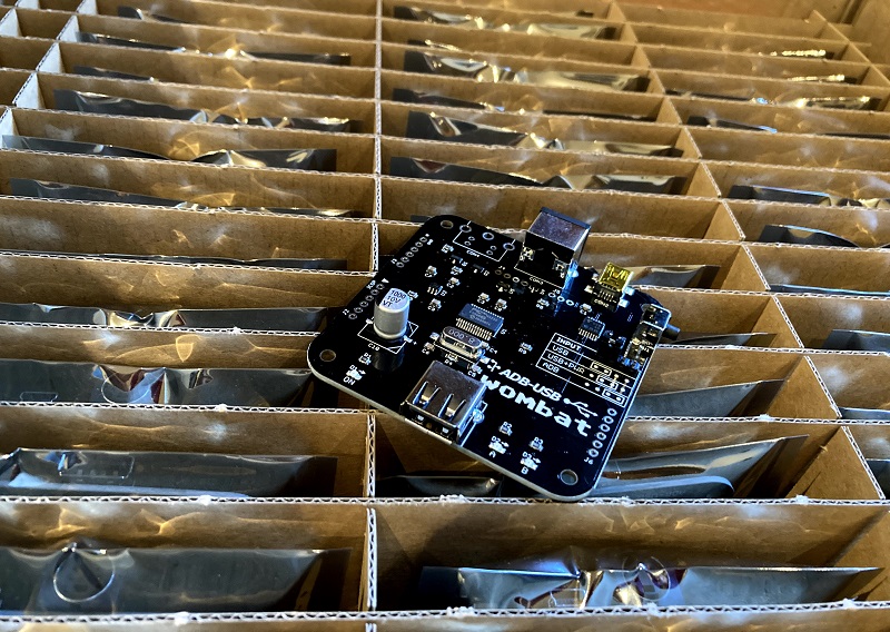
Firmware version 0.3.7 is now available for the Wombat ADB-to-USB input converter. This version fixes a compatibility problem with some ADB mice that use non-standard communication timing. You can download the new firmware here.
This was an interesting discovery. Apple only ever produced a few different ADB mice, with model numbers A9M0331, M2706, and G5431. You might think that mice with the same model number would be the same, but in fact there are several different versions of each model and they have very different internal parts. It may be possible to tell them apart by checking the country of manufacture printed on the mouse, which could be USA, China, Malaysia, Taiwan, or others.
Some of the “Made in Taiwan” ADB mice have a controller chip inside that’s made by Logitech rather than Apple. These mice communicate over ADB at 75 microseconds per bit, instead of at the normal rate of 100 microseconds per bit. A small change to the Wombat firmware was required to make it more flexible about the bit timing.
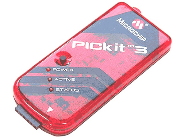
PICkit 3 R.I.P.
The Wombat is designed around a Microchip PIC32 microcontroller, and I use a Microchip PICkit 3 to program and debug. Somewhere within the last year or so, the PICkit 3 has basically stopped working. It gives every indication of being some kind of Windows 10 problem or USB driver issue, rather than a hardware problem with the PICkit 3. Searching the web turns up many similar complaints, but no solution.
Using Microchip’s MPLAB X IDE for development and debugging, the PICkit 3 doesn’t work at all. The IDE will detect that it’s there, but any attempt to actually use it just gets a “connection failed” error. This means that I can’t use the debugger, and I’m reduced to debugging using print statements over the serial port.
The PICkit 3 sort-of works with the MPLAB IPE, a stand-alone programming tool with no debugging capabilities. But it only works for a short window of time after rebooting my computer. After a few programming cycles, it falls back to the same “connection failed” behavior as the IDE. The only way I’ve found to fix it is to reboot… again. Unplugging and replugging the PICkit3 doesn’t help, nor does updating the PICkit 3’s firmware, restarting MPLAB, or anything else I can think of. The word from Microchip’s own support is basically “Oh, you bought one of THOSE? Ha ha ha. Yeah, those PICkit 3s don’t work very well and we’ve dropped support for them.”
After spending quite a long time trying to resolve this, I eventually gave up, and decided I won’t be using any PIC parts for any future projects. The tools are just too clunky and buggy, and there doesn’t seem to be nearly as large of a community using PIC32 parts as other options like STM32. That means that when something’s not working, there aren’t many people who can offer help, and you’re basically out of luck. Too bad.
Read 3 comments and join the conversationYellowstone: Ready for Takeoff
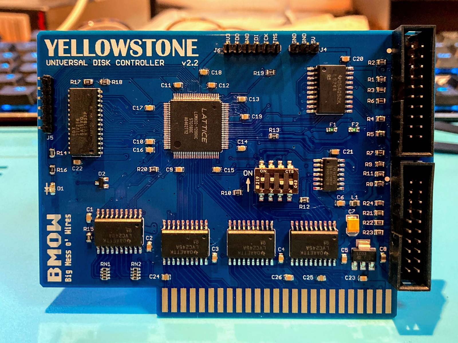
After several days of extensive testing with the latest Yellowstone prototype, and several years of development work on this universal Apple II disk controller concept, I’m here to say that Yellowstone v2.2 is looking good. Looking very good. It’s the bee’s knees, the cat’s pajamas, the whole package; it’s a humdinger, a totally gnarly wave; it’s crackerjack, boffo, hella good, chezzar, d’shiznit, on point, and just plain bombdiggity. I’ve thrown a dumpster-load of assorted drives and disks at it, and it’s all working nicely. Finally everything has fallen into place, and I’m excited for what comes next. Here are some feature highlights:
- Supports most Apple II and Macintosh disk drives, including 3.5 inch floppy, 5.25 inch floppy, Unidisk 3.5, and Smartport hard drives
- Compatible with Apple II+, Apple IIe, and Apple IIgs
- Maximum of 2 standard disk drives, or up to 5 drives when mixing smart and standard drives
- 20-pin ribbon cable or 19-pin D-SUB connectors
- Works in any slot
- Disk II compatibility mode for tricky copy-protected disks
- User-upgradeable for future feature enhancements
Yellowstone supports basically every disk drive ever made for the Apple II or Macintosh, whether external or internal. The only exception is the single-sided 400K 3.5 inch drive used in the original 1984 Macintosh. The list of drives includes:
- Standard 3.5 inch: Apple 3.5 Drive A9M0106, Mac 800K External M0131, Apple SuperDrive / FDHD Drive G7287 (as 800K drive), internal red-label and black-label 800K drives liberated from old Macs, internal auto-inject or manual-inject Superdrives (as 800K drive), and probably also third-party 3.5 inch drives from Laser, Chinon, AMR, Applied Engineering, and others.
- Standard 5.25 inch: Disk II A2M0003, Unidisk 5.25 A9M0104, AppleDisk 5.25 A9M0107, Disk IIc A2M4050, Duo Disk A9M0108
- Smart drives: BMOW Floppy Emu Smartport Hard Disk emulation mode, Unidisk 3.5 A2M2053
- Drive emulators: BMOW Floppy Emu, wDrive, etc.
With these latest test results, we’re almost at the point where other people can start to get their hands on Yellowstone cards. There are surely still some minor bugs, quirks, and annoyances yet to be discovered, and maybe some larger problems too. I need to get a few Yellowstone prototypes to beta testers, so they can try the cards with their equipment, and help find any remaining issues.
My priority now is to finish the automated tester that I’ve been developing. As I hand-assemble a few more prototype boards, I’ll test them in the automated tester, proving both the tester and the board at the same time. That means delivery of boards to beta testers will proceed more slowly than if I weren’t developing an automated tester, but I think this is necessary so that I can eventually scale up manufacturing for a general public release. I’m guessing there may be four to six weeks needed to finish off the automated tester and build it, but hopefully I can squeeze out at least a couple of hand-verified prototype boards much sooner than that.
The last piece of this puzzle will be securing a large enough supply of DB-19 female connectors, and designing a detachable Yellowstone adapter for them. I have a couple of DB-19F adapters that I’ve been using for testing, but DB-19F connectors are rare and hard to find. The ones I have now use a DB-19F with solder cups, but the type with PCB pins seems to be more common, if you can find them at all. I’ve stashed a modest supply of DB-19F connectors that’s enough for an initial Yellowstone production run, but the outlook is uncertain beyond that. I may have to commission 10000 new ones like I did with the DB-19 male.
These are exciting times! Thanks for following along this journey with me.
Read 9 comments and join the conversationFloppy Emu Update: Smartport and More

Hello! I’m Alice, the engineering intern here at Big Mess o’ Wires. I’m a math with computer science major at UC San Diego, and throughout the summer I’ve been working on some fixes and improvements for BMOW products. I started out on the ADB-USB Wombat, but most of my work has been on Floppy Emu development.
Today, I’m excited to finally share what I’ve been doing! Here is a collection of some of the new Floppy Emu improvements. They’re mostly related to Smartport and Unidisk 3.5 emulation for the Apple II, but there’s some other good stuff too.
Smartport Hard Disk and Unidisk 3.5 emulation:
– Control commands are now handled better. This resolves GS/OS freezes during shutdown or restart, and related problems with other software.
– A NAK/retry mechanism was added for cases where there’s a checksum failure on a Read or Status command. It will provide more robustness against signal noise.
– Status commands that request invalid or unsupported status types will now receive a proper error reply.
Unidisk 3.5 emulation:
– Emulation now continues to run even while displaying the disk selection menu. It will respond to commands as an empty drive, instead of not responding at all. This resolves some potential problems when booting from other disks and when swapping disks.
– Handling of disk ejection has been improved. Disks can now be ejected and replaced through the GS/OS Finder menu and other methods of software-controlled disk eject, as well as through the Floppy Emu menu interface.
– The disk icon that’s displayed in GS/OS has been updated to look like a 3.5 inch floppy disk.
General improvements:
– Occasional errors CHECK PIN CLKO-L and CHECK PIN RESET should no longer occur.
– Hidden system directories on the SD card will not be displayed in the disk selection menu, including Windows 10’s “System Volume Information” directory.
– OLED screen dimming behavior is now more consistent.
These improvements are available in firmware versions 0.2T-F30, 0.2S-F29-SPDC, 0.2S-F26, and 0.2H-F15 (depending on the Floppy Emu model and the type of computer it’s used with). You can download the new firmware files on the Floppy Emu page. Let us know if you run into any issues, and have fun!
Read 6 comments and join the conversationNew Cases for the Daisy Chainer!
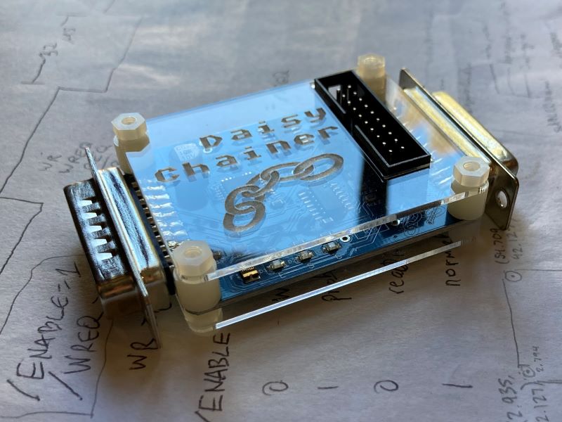
Hello! If you haven’t met me already, I’m Alice, the BMOW engineering intern. (You might hear more about what I’ve been up to soon.) I’m excited to share that after several stages of redesign, cases for the Daisy Chainer are finally here! These clear acrylic enclosures will protect your Daisy Chainer and show it off with style. This is a plate style case similar to the ADB-USB Wombat with open sides and a logo-etched top. Available now on the store!
Yellowstone 2.2 First Look
Yellowstone version 2.2 is up and running! If you don’t remember what’s changed in v2.2, well… that makes two of us. Luckily we can both go read this August 20 post for a reminder. Hand assembly took about two hours, and this was the first time any of the Yellowstone prototypes have worked straight away without needing any troubleshooting or fixes. The board has only been through one superficial test so far, confirming the ROM contents and booting a 5.25 inch disk, but I’m feeling optimistic it’s a winner.
After going through board v1.0, v2.0, v2.1, and v2.2, I’m sincerely hoping that this will be the final hardware version. The return of the DIP switch is the most visible change here – now the much-discussed -12V supply can be manually enabled or disabled. Leaving it enabled will almost always be OK, but there are a couple of polyfuses to protect the hardware just in case. There’s also a fix in v2.2 for a minor problem that prevented an Apple 3.5 Drive’s eject button from working if the drive was plugged into Yellowstone’s connector #2.
There are still some software issues to clean up, but (crossing my fingers) I think I can see the finish line now.
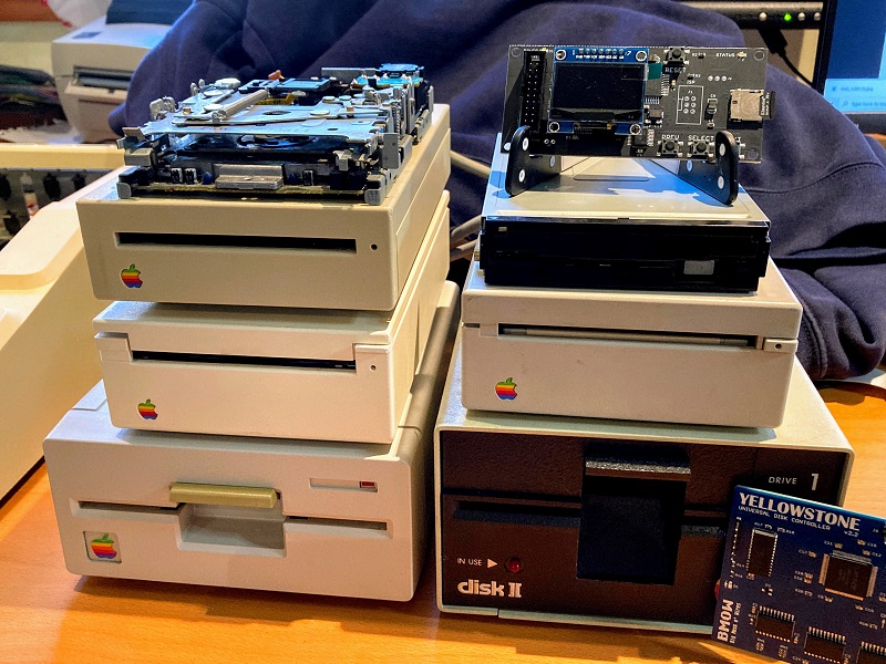
Just for fun, here’s a shot of the new Yellowstone board along with all of the disk drives I’ve amassed for testing. All of these will work with Yellowstone, and many others too.
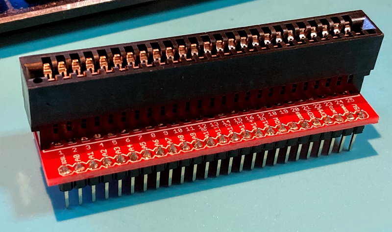
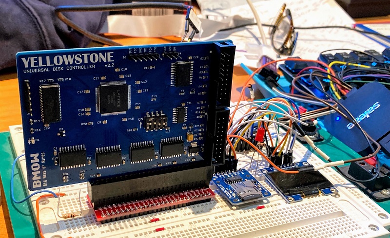
And a bonus feature: here’s a peek at a 50 pin Apple peripheral card breakout board that I whipped up. It has all the signals labeled, because I don’t trust myself while debugging. With this breakout board, it’s possible to run a peripheral card on a breadboard instead of inside the Apple II. That’s exactly what I’m doing with the work-in-progress version of the Yellowstone tester shown here.