

Death of an M0131 Floppy Drive
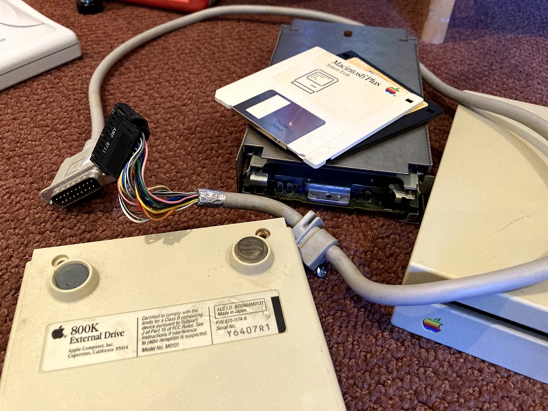
Recently I bought an external 800K Macintosh floppy drive, model M0131, so I could confirm its compatibility with my Yellowstone disk controller card for Apple II computers. The testing didn’t go as planned, and now the drive is dead, but it’s not Yellowstone’s fault. I’m still not clear exactly what happened. Here’s a rundown of my testing misadventures.
For the first test I connected the drive to a Macintosh SE, to confirm everything was OK before moving on to Yellowstone testing. This is the original SE model with an internal 800K floppy drive, not the later SE FDHD model that supports 1.44 MB floppy drives. Immediately after turning on the computer, the M0131 drive began continuously running its eject motor, trying again and again to eject a non-existent floppy disk. I quickly turned off the computer. Hmm, strange.
I connected the drive to a Macintosh SE/30. This time there was no strange eject behavior, but the drive made some ominous noises when I inserted a floppy disk. It was unable to read the floppy. That wasn’t good, but at least it seemed to be a small improvement over mystery ejections. So I returned to the Macintosh SE, naively hoping it would somehow behave differently this time. Nope. The drive still tried to eject-eject-eject for as long as the power remained on.
Back to the SE/30, I tried the drive once more and found success! I was able to read a couple of Mac floppies that I grabbed at random for testing. That was good news. Returning to the Mac SE for a third time, hoping that something would have magically changed there, the drive still tried to eject-eject-eject. This time I let it run for a while, under the theory that maybe it would stop ejecting after the System started to load from the internal hard disk. After 10-20 seconds, the eject-eject-eject cycles gave way to a continuous high-pitched whirring, and an unpleasant smell appeared. Uh oh… Moving back to the SE/30, now I could only get the same continuous high-pitched whirring, and no drive function. It seemed that the magic smoke was released. RIP, brave M0131.
Next I disassembled the drive enclosure. There was nothing of interest inside except for the drive mechanism and some brackets – there are no other electronics. So the M0131 external drive is essentially just an internal 800K floppy drive in a plastic box with a DB-19 to rectangular 20-pin cable. I tried to remove the drive mechanism to inspect it more closely, since it’s fully enclosed in a sheet metal tray. But one of the mounting screws was crusty with age, and I was unable to remove it, no matter what tools I used or how hard I tried. Unfortunately that means I now have a $100 doorstop.
-12V Strikes Again?
What happened here? I have a theory it’s somehow related to my old friend pin 9, which may be either -12V or +5V depending on the particular drive and the computer model, and which I’ve discussed here several times over the past weeks. I’m vaguely aware that continuous ejection is a somewhat common symptom of floppy drive cable problems in the earliest Macintosh models. If you mix and match floppy drives and drive cables between mid-1980s Macintosh models like the Plus, SE, 512K, and 128K, you will sometimes see this mystery ejection behavior. Internet wisdom says the solution is related to using yellow-striped disk cables instead of red-striped cables, but I’ve never bothered to understand the root cause or what the difference is between those cable types. You’ll find one discussion of this issue at VCFED, where one of the commenters also specifically mentions pin 9.
This is just a guess, but it wouldn’t surprise me if the original model Macintosh SE has a -12V supply connected to pin 9, but the newer Macintosh SE/30 has nothing on pin 9. If this M0131 drive has +5V on pin 9, and the short-circuited voltage supplies somehow caused the eject motor to unintentionally activate, that might partially explain why the drive worked on the SE/30 but not on the SE. But it still doesn’t entirely make sense, because the M0131 should definitely work on a Macintosh SE, and it was released a year before the SE. Maybe the drive mechanism in this particular M0131 was just bad, or the cable?
An 800K Impostor?
I have another crazy theory which is probably wrong. Maybe this was actually a 1.44 MB drive mechanism in a M0131 enclosure, the result of somebody’s past Frankenstein experiment or an “upgrade” when the original mechanism failed. From past testing, I know that pin 9 on the 1.44 MB drive mechanism is +5V. Maybe on the 800K mechanism, pin 9 is N.C., not connected? If that’s true, and my guess about pin 9 on the Mac SE and Mac SE/30 is also true, then it could explain everything that happened here. An M0131 enclosure with an 800K mechanism on a Mac SE would result in -12V connected to N.C., and would work OK. The same equipment on a Mac SE/30 would result in N.C. connected to N.C., and would also work OK. If a 1.44 MB drive mechanism were transplanted into the enclosure, with +5V on pin 9, it would result in N.C. connected to +5V, and would still work OK. Any computer newer than a Mac SE would likely also work. But on the SE, it would result in -12V connected to +5V, creating a short.
Two pieces of evidence may be helpful here – one that supports this crazy theory and one that refutes it. From what little I can see of the drive mechanism while it sits inside the sheet metal tray, it doesn’t look like a 1.44 MB mechanism. I say that based on its distinctly old-school look, with lots of large discrete components visible on its PCB. The crusty old screw that defeated my attempts to remove it also suggests that the drive mechanism hasn’t been removed any time recently. But that may not be a reliable indicator of anything.
On the other hand, I belatedly realized that one of the floppy disks that worked briefly on the SE/30 was a high-density 1.44 MB floppy disk. This shouldn’t have been readable in the 800K mechanism of the M0131! At least I don’t think so. It’s a question I’ve never really considered before. All of the extra smarts necessary for 1.44 MB floppy support are in the computer – in the SWIM chip and in the system ROM software, not in the drive. So what actually is the difference between an 800K drive mechanism and a 1.44 MB mechanism? The 800K mechanism spins at different speeds depending on which track is being accessed; the 1.44 MB mechanism can do this too, or it can spin at a fixed speed for all tracks. My guess is that the only really important difference is in the read/write heads. The 1.44 MB drive probably has smaller heads that can read and write weaker magnetic fields, to support the closer bit spacing on 1.44 MB disks. But it wouldn’t completely shock me to learn that an 800K drive could also read 1.44 MB disks, albeit with a lot of errors and poor performance, if it’s connected to a computer with a SWIM chip like the Mac SE/30. So I’m not sure whether reading that 1.44 MB disk really proved anything one way or another.
Unsolved Mysteries
Now that the drive is dead, the answer to this mystery will unfortunately remain unknown. I’m still 99 percent sure that the M0131 and other Macintosh floppy drives will work OK with Yellowstone version 2.1, but confirmation will have to come from a beta tester. Meanwhile I have a cool paperweight.
But Wait, There’s More
I finally managed to remove the crusty screw and extract the drive mechanism, revealing that my crazy theory was correct, and it’s actually a 1.44 MB drive in an 800K M0131 drive enclosure. The part number MP-F75W-12G matches a known part number for Apple 1.44 MB drives, and the “2MB” text (the raw capacity of a 1.44 MB drive) also confirms it.
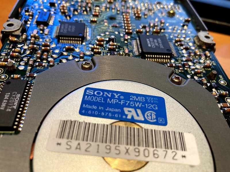
This seems to be an older example of a 1.44 MB drive than the one I’d previously been using for Yellowstone testing, and unlike that one, this drive’s pin 9 is not connected to +5V. It’s not connected to any other pin on the disk connector either. Unfortunately I can’t tell what pin 9 is connected to internally; I tried to follow the PCB trace but it disappeared into a confusing network of resistors and vias. Judging by the width of the trace, I’m guessing it’s a signal of some type rather than a voltage supply.
A few more pieces of data: The DB-19 to rectangular 20-pin cable on the M0131 enclosure connects DB-19 pin 5 to rectangular pin 9. That’s consistent with the expectation that this pin should be a -12V supply, and it’s where -12V is shown on the published pinouts of both types of connector. On the Mac SE, at the external DB-19 floppy port, I measured -11.7V on pin 5. But on the Mac SE/30, at the external DB-19 floppy port, I measured 0 volts on pin 5. I’m not certain if that reading on the SE/30 means the pin is grounded, or not connected, or something else. My prediction is that it’s not connected.
So now everything makes more sense, except for what the 1.44 MB drive was doing inside the M0131 enclosure. But I still don’t know what pin 9 on this 1.44 MB drive is intended to be used for, or why supplying -12V on the pin caused the drive to continuously eject.
There’s also a new concern for Yellowstone. Until now I had been building my plans for Yellowstone support of Macintosh drives from tests of one specific 1.44 MB drive, which I assumed would have the same pinout and behavior as any other Mac drive. It seems that I was wrong. On my original test Macintosh 1.44 MB drive, pin 9 is a +5V connection, and I designed the latest Yellowstone PCB version 2.1 around that fact. But on this Macintosh 1.44 MB drive, pin 9 is something unknown, maybe related to the eject motor. That means Yellowstone 2.1 may not work correctly with this type of Mac drive. It also raises the possibility that a true 800K Mac drive mechanism may be different than either of these 1.44 MB examples.
After almost ten years of making it my business to know everything possible about Apple floppy drives, I’m surprised to discover that something as fundamental as this drive pinout difference has escaped my attention. Live and learn.
Read 15 comments and join the conversationDisk Drive Testing
While I await the new Yellowstone v2.1 PCBs, I’ve been spending more time on testing. With my hacked-up v2.0 PCB, most things are working pretty well, especially with DOS3.3, ProDOS, or game disks. I can connect any odd combination of drives to the Yellowstone card, and expect that it will behave more-or-less correctly, but of course there are still a few bugs. Here’s what I’ve been working on recently.
Laser Bugs
Yellowstone supports booting from drive 1 or drive 2, but I noticed that if both drives were 5.25 inch floppies, then attempting to boot from drive 2 would always crash the computer. To find the cause, I had to go digging deep into the Laser ROM on which Yellowstone’s core disk routines are based. After some effort, I identified this as a bug in the original Laser ROM. With this drive configuration, if booting from drive 1 failed, it would prepare to boot drive 2 but never actually load anything from the disk. Then it would attempt to run the code in the uninitialized memory buffer where track 0 sector 0 was supposed to have been loaded. Doh! This is a surprisingly severe bug to find in a successful product from a major company in the 1980s, but maybe expectations were different back then.
I found another Laser-related bug in the 3.5 inch drive support. Although Yellowstone was already working OK for 3.5 inch drives, the disk I/O sounded like a panicked chicken or one of The Muppets. While reading from a disk, the 3.5 inch drive made an odd mechanical sound several times per second, which was not present when using the same drive with other disk controllers. I eventually tracked this down to the 3.5 inch / 5.25 inch switching behavior. After every sector read from the 3.5 inch disk, the Laser ROM routine was switching back to 5.25 inch mode before exiting, only to immediately switch back again for the next sector. This was causing the drive to turn on and off rapidly. I’m not sure how that made it through anybody’s QA process, because it made an obvious unpleasant noise.
With the Apple IIgs, if you boot the computer with a DOS3.3 disk using another controller card in a higher-numbered slot than Yellowstone, then Yellowstone’s ROM initialization code will never have an opportunity to run. The motor detectors for Yellowstone’s slot will never get enabled, so the IIgs won’t slow to 1 MHz when attempting to do I/O with Yellowstone’s drives. The result will be a garbled mess. Fortunately this is pretty obscure, and it only affects software based on DOS3.3 and not ProDOS, and where Yellowstone is not the primary boot device. I don’t think there’s any complete fix, but there are several possible work-arounds, including manually running the initialization code with PR#x for Yellowstone’s slot number.
GS/OS
Some other bugs I’ve identified, but not managed to fix yet. Most of them are related to GS/OS. When sitting at the desktop, GS/OS makes a Status call for each drive every 800 ms. I assume this is so it can update the GUI, and change a disk’s icon when it’s been swapped or removed. But this creates a problem for Yellowstone. Part of the data that’s returned by a Status call is the size of the disk. For 3.5 inch disks, the size is different for single-sided 400K disks and double-sided 800K disks, but it can’t know which type of disk is in the drive until it tries reading it. So every 800 ms, the drive spins up to read the disk and see whether it’s double-sided, over and over forever. It’s very distracting, and other disk controllers don’t have this problem. The Yellowstone Status call handler is going to need more smarts to cache the disk info instead of re-reading the disk each time, and to know when the drive must be checked again after a disk swap.
Yellowstone 5.25 inch drives currently aren’t working great with GS/OS, because GS/OS doesn’t know they’re 5.25 inch drives. It thinks they’re some new type of drive that supports standard API calls and that just happens to be 140K in size, so it treats them the same way as 3.5 inch drives, including the every 800 ms status call. But 5.25 inch drives can’t work that way. If you boot GS/OS while having a 5.25 inch disk in the drive, then everything works OK at first. But if you remove that disk and insert another one, GS/OS won’t know about it. If you click on the 5.25 inch drive icon, it’ll ask you to reinsert the original disk and there’s no way switch disks. If you boot GS/OS while having an empty 5.25 inch drive connected, it will complain that the disk can’t be read and needs to be initialized. If you cancel that, then the 5.25 inch drive disappears from the GS/OS desktop, never to be seen again.
With a standard Disk II controller card, or the built-in disk port of an Apple IIgs, 5.25 inch drives have a different behavior than other types of drives under GS/OS. It doesn’t attempt to access the drives or check their status until you choose to open them. As I recall, it also shows the 5.25 inch drive with a separate icon from the disk that’s in the drive. I’m not sure how to force GS/OS to treat Yellowstone 5.25 inch drives the same way, or if it’s even possible. The behavior may be determined by a signature check of the disk controller’s ROM, and if it looks like a Disk II controller, it’ll use the special 5.25 inch drive behavior. There might be a work-around if you’ve booted GS/OS from another drive and disk controller, and are then accessing one or two 5.25 inch drives using the Yellowstone card. But if Yellowstone is your only disk controller, with a Smartport hard drive at D1 and a 5.25 inch drive at D2, I’m not sure what the solution might be.
Floppy Emu
The Floppy Emu disk emulator has been my go-to testing device for use with Yellowstone, and I’ve found a couple of bugs with it too. When Floppy Emu is configured as a Unidisk 3.5 drive, but no disk is inserted yet, it displays a menu for selecting a disk. During this time the disk emulation is paused, and if the computer queries the drive, it will appear unresponsive. If you’re planning to boot from the emulated Unidisk 3.5 then you’ll probably never notice this, but if you use the Yellowstone card to boot from a ProDOS disk in another drive, then ProDOS will fail with a “Relocation/Configuration Error” mid-way through booting when it queries the Floppy Emu and gets no response.
In researching possible solutions for the GS/OS Status Call, I also realized that Floppy Emu isn’t correctly emulating one of the Sony 3.5 inch drive’s internal registers called SWITCHED. I had never found any documentation about this, so years ago when I created the emulator framework, I made this register always return zero. But now I realize that’s wrong. After experimenting with a real 3.5 inch drive, I see how it’s supposed to work. At power-on the SWITCHED register should be zero, and it should change to 1 if a disk is ejected automatically or manually with a paper clip. Software can set the value back to zero again. This probably explains why a few old Macintosh games like Dark Castle don’t seem to recognize when a new disk has been inserted, when they’re run from a Floppy Emu.
It’s not a Bug, it’s a Feature
With the exception of the GS/OS items, I think most of these issues should be possible to fix, and if I’m wrong then they’re at least easy to identify and work-around. But I’m a little worried about 5.25 inch drive handling under GS/OS. Hopefully it’s just a matter of providing the right flags in response to the Status call and other API calls. I suppose it’s not the end of the world if it never works, since most people who are running GS/OS with Yellowstone will have a separate Disk II card or the built-in disk port for their 5.25 inch drives. But I’d love to make this combination work if I can.
Read 15 comments and join the conversationBack-Powering and Phantom Power From JTAG
Throughout Yellowstone’s development, I’ve struggled on and off with mysterious problems related to the JTAG programmer. When the programmer is connected to the Yellowstone card, and I turn the computer off and on again, strange things sometimes happen. The Apple IIGS will boot to a screen of green and pink checkered squares, or will beep continuously, or simply freeze. This condition will often persist across multiple on/off/on cycles of the computer’s power switch. Unplugging the JTAG programmer finally returns everything to normal.
I assumed the JTAG programmer was somehow back-powering the Yellowstone card, which in turn might even have been back-powering the computer. When the computer was off, but the JTAG programmer was on (it’s a USB device connected to my PC), it looked like a small amount of power was being provided by the JTAG programmer to the Yellowstone card. In the past I made some half-hearted attempts to troubleshoot the issue, but never really got anywhere, and stopped worrying about it. Yesterday I took another look at the problem.
The JTAG programmer connection has six pins: VCC, GND, TCK, TMS, TDI, and TDO. The VCC pin is used by the programmer to sense the target board’s voltage, so it can set the level of the other data signals properly. Under normal conditions, that means a small amount of current is flowing from the Yellowstone card’s 3.3V supply rail through the VCC pin to the JTAG programmer.
Experiments
How does this work? I disassembled the JTAG programmer to see. Its output stage consists of a 74HC244 and a 74HC07, both of which are powered directly from the VCC pin of the target board. That ensures the output signals will be at the right voltage level. So far, so good. But I also saw several resistors (pull-ups?) between the VCC trace and other signals on the JTAG programmer PCB. Some of these go back to the programmer’s own 3.3V regulator, or to I/O signals from the programmer’s built-in microcontroller. With a multimeter, I measured about 1.4K ohms between the programmer’s 3.3V supply and the VCC trace for the target board. So when the target is off, it will be back-powered by 3.3V through 1.4K ohm from the programmer. That’s not great, but the true situation is likely worse, because there’s probably also additional unwanted current coming from the microcontroller I/O signals depending on what state they’re in, and the effective resistance may therefore be lower.
I put everything back together, reconnected the JTAG programmer, but did not turn on the Apple IIgs. With the computer still off, I measured the voltage on Yellowstone’s 3.3V supply rail, and saw 1.3V. Then I measured the voltage on the 5V supply rail and saw 0.5V. Doh! I’m not certain how the FPGA and the computer will behave with those low voltages, as they’re certainly too low to run anything normally, but they may be enough to keep some components half-alive in a strange zombie state. Then when the power is turned on, those components don’t initialize normally, and weird things happen. I’m not sure exactly what the mechanism is, but holding the supply at 1.3V instead of zero when the device is off certainly seems like it could cause strange behavior.
The solution seemed obvious to me: put a diode between the 3.3V supply and the VCC pin on the JTAG header. That would allow current to flow out to the JTAG programmer during normal use, but prevent current from flowing in on the VCC pin when the computer is off. The JTAG programmer would see a voltage that’s a diode drop below 3.3V, so the JTAG signals would also be the same amount lower, but the signals should still be plenty high enough to work. To my poor Yellowstone board that’s already suffered so many cuts and patches, I made one more cut and patched in a 1N914 diode.
With the diode installed, JTAG programming still worked normally. The mysterious green/pink checkerboards seemed to have disappeared. With the computer off, I measured 0 volts on Yellowstone’s 3.3V supply rail – hooray! But unfortunately I’d celebrated too soon. While the diode seemed to fix the problem when the JTAG programmer was connected in its default power-up state, it was a different story after exercising the JTAG programmer a bit. I found that if I turned on the computer, used the JTAG programmer to update the FPGA, and then turned off the computer again, Yellowstone’s 3.3V supply rail showed 1.25V and the IIGS would freeze when turned on again. What??
Phantom Power
My experiments ended there, but I suspect the difference is due to the state of the TCK, TMS, and TDI pins. If these are low, then my diode on VCC fixes the problem. But if any of these are high, as they may be after concluding a JTAG operation, I suspect that Yellowstone is being powered through the TCK, TMS, and TDI pins.
How? Like many ICs, Yellowstone’s FPGA has clamp diodes on its input pins. Under normal use, the diode is meant to protect the input buffer if the voltage ever rises too high. It’s just a built-in diode from the input pin to the VCC supply. But when the FPGA is off, this means the chip can actually be powered by supplying a voltage at any input pin, which will raise the VCC supply rail to a voltage that’s a diode drop below the input voltage. This is called “phantom power”, and there’s plenty of discussion about it on the web. It’s not something you want to do intentionally, because the clamp diodes aren’t designed for this purpose, and can’t handle very much current. But in my case, unwanted phantom power seems to be the cause of the problem.
But wait: if the TCK, TMS, and TDI signals are coming from that 74HC244 chip I mentioned, and that chip is powered from Yellowstone’s VCC (which is at 0V thanks to the diode I added), then how can those three signals ever be high? My theory is that the 74HC244 is itself being phantom powered by the JTAG programmer’s microcontroller.
Is there a way to fix this? Additional diodes probably won’t help here, because the direction of current flow is the same for the normal case and the problem case. The only simple fix I can think of is to add a dummy resistor between Yellowstone’s 3.3V supply and GND, guaranteeing a minimum load of at least a few milliamps regardless of what the other chips on the board are doing. That way even if some phantom power is applied, the load will be enough to prevent the 3.3V supply rail from rising high enough to cause trouble, because the phantom power can’t (presumably) supply more than a couple of milliamps at most.
But the devil is in the details. Under normal conditions a 1K resistor would create a continuous 3.3 mA load on the 3.3V supply, but with phantom power the situation is different. There’s already several kiloohms of resistance due to who-knows-what between the phantom power source and the Yellowstone supply rail, so adding what’s effectively a 1K pulldown resistor doesn’t change things very much. I calculated that I’d need a dummy load resistor of just a few hundred ohms to move the needle enough, and reduce the VCC voltage due to phantom power to a point where I could be confident it wouldn’t cause trouble. But a resistor value that low would put an unacceptably large load on the 3.3V supply during normal conditions.
There’s probably some clever solution here, but I’m not going to worry about it. This problem only affects me and my development work with the JTAG programmer, so I’ve decided to ignore it. It’s not an important enough issue to be worth additional time and effort, I think. But it’s an interesting little detour into unexpected failure modes of electronic devices.
Read 4 comments and join the conversationFour Years of Yellowstone
July 21, 2017 – I began the first work on what would become Yellowstone, with some attempts at designing a Verilog model of Apple’s IWM chip. Four years have passed since then, and I’m still working on this project! Today version 2.1 of the Yellowstone PCB is nearly ready for fabrication. V2.1 contains a pile of changes and improvements based on my tests of V2.0 over the past weeks. Some of the highlights:
- Added 2.2K series resistors on the -12V supply for J1 and J2, to safely limit current if a Macintosh 3.5 inch drive is connected. (bypassable with a solder jumper)
- Inserted 33 ohm series resistors on the data bus lines, to reduce ground bounce caused by fast-switching signals
- Replaced the DIP switch for selecting Disk II mode with a firmware-driven activation
- Removed the DIP switch for manually routing /ENABLE2 to J1 or J2, in favor of a firmware-driven solution
- Routed /ENABLE2 through two open-drain buffers to the two drive connectors, so a pull-down from one drive won’t make the other drive think it’s enabled
- Routed the RD and SENSE signals from each disk connector independently to the FPGA, so it can tell which drive is responding and handle error conditions when they both respond at the same time
- Added a “recovery” jumper that connects A11 through a resistor to the FPGA’s SPI /CS input, to support in-system programming of mis-programmed or blank FPGAs.
- Added decoupling capacitors on all four power supplies
- Added more ground fills, and lots more vias connecting top and bottom-side fills
- Rerouted and widened power supply traces, and repositioned bypass capacitors
- Fixed a spot where D5 overlapped a power supply trace. Oops!
- Fixed an enable signal that was connected directly to +5V instead of with a pull-up resistor. Oops again!
- Fixed the wrong supply voltage connected to one of the chips. Oops a third time!
It’s been a long journey, but everything is finally coming together. If all goes well I may have a beta-ready board in a few weeks.
Read 6 comments and join the conversationYellowstone Ground Noise and Bypass Capacitors
I’m working on what I hope will be the final hardware changes for the Yellowstone 2.1 PCB. Among these are changes to my capacitor usage and placement strategy. In my previous posts I discussed intermittent problems that looked to be caused by ground bounce, VCC sag, or both. Apple II expansion cards only have a single ground pin on the motherboard connector, so they’re prone to ground noise when signals with fast rise and fall times cause large transient currents. Among several methods that I’ve used for mitigating this problem, one not-so-obvious strategy is to add bypass capacitors on the +12V, -12V, and -5V power supplies, even if the card doesn’t use those supplies.
Apple IIgs Technote #68 says:
Right now Yellowstone doesn’t use or bypass the +/-12V supplies; it just routes them through to the disk drive connectors. -5V is completely unused, and there’s nothing at all connected to that supply pin. I had actually forgotten there even was a -5V supply. (Maybe this could be leveraged somehow for current-limiting of Macintosh drives?)
Why does bypassing unused supplies help anything? Even after doing lots of reading about current loops and ground bounce and impedance, I have to admit I don’t really understand it. I read a T.I. paper that discussed how bypass capacitors help reduce the area of current loops, but I don’t see how that’s true for bypass capacitors on unused supplies, where there’s no path back to the chip that’s sourcing or sinking current. The Apple technote mentions “improved ground by providing additional AC ground paths”, which makes a little more intuitive sense to me. I imagine the bypass capacitors as acting like tiny batteries that work to maintain the voltage between their two terminals. As long as +12V, -12V, and -5V are stable, then bypass capacitors on those supplies will work to keep local ground at 0V by sourcing or sinking small amounts of current as necessary.
I probably wouldn’t really care why it helps, and would just trust that it does, except that I need to know what types and values of bypass capacitors to use, in what locations. Without a better understanding of the theory of why it helps, I’m uncertain how to proceed.
The Apple technote specifically says electrolytic or tantalum capacitors, but doesn’t mention ceramic, which would normally be my go-to for this. I’m not sure why they omitted ceramic.
For the capacitor value, Apple doesn’t say anything. Is a standard 0.1 uF appropriate? I believe the 0.1 uF rule-of-thumb is related to the rise and fall times of typical ICs, and an assumption that the capacitor is placed within a few millimeters of the IC supply pin. But when there’s no specific chip being bypassed, how do you determine the appropriate value? Would a larger value like 1 uF make more sense?
Then there’s the question of placement. I can’t place the bypass capacitors near the IC supply pins, because there are no ICs using +12V, -12V, or -5V. Should I put the capacitors near the board’s supply pins on the motherboard connector? Or maybe in the middle of the board?
My best guesses are that a ceramic capacitor would be fine as long as its voltage rating is high enough, the capacitor should be placed close to the motherboard connector, and the value should be something like 1 uF or 10 uF. Or maybe multiple values with multiple capacitors per supply. I don’t want to rain down tons of extra capacitors though, because the number of discrete components on the PCB is already higher than I’d like.
Read 11 comments and join the conversationCurrent Limiting, Part 3
I’ve been searching for a simple and reliable way to prevent a short-circuit on Yellowstone’s -12V supply when a particular type of Macintosh disk drive is connected. Connecting this drive results in a +5V to -12V short circuit, but if the short is removed, the drive otherwise works just fine. One obvious solution is to put a series resistor on the -12V supply connection. For example a 1.7K ohm resistor would limit the short-circuit current to a safe 17V / 1.7K = 10 mA. But a series resistor on the -12V supply for Macintosh drive protection would obviously screw up other types of drives, by making the supply appear to be something other than -12V volts. Obviously. Or maybe not so obviously.
When I actually tested it, I was very surprised by the results. As far as I know the -12V supply is only used by Disk II drives. A 1.8K series resistor on the -12V supply for a Disk II drive resulted in an apparent supply voltage of -8.7V, but the drive still worked fine. I then tried larger value resistors resulting in “-12V” supply voltages of -6.5V, -5.0V, and -0.8V, and everything continued to work. Even at +3.7V the drive continued working, but I/O was slightly slower than normal, suggesting that a high number of retries were happening. The drive finally failed after I reached 100K ohms and +6.9V for the so-called -12V supply.
How can this be? How can the -12V supply voltage accuracy matter so little? What is it used for?
Looking at the schematic for the analog board of a Disk II drive, -12V is only used in one spot, at one terminal of a 10K potentiometer at the bottom-right. It’s part of an analog reference adjustment for the MC3470, the drive’s floppy disk read amplifier circuit. Pages 7-119 to 7-120 of the MC3470 datasheet describe how it adjusts the differential amplifier that’s used to detect peaks in the AC signal from the drive’s read head.
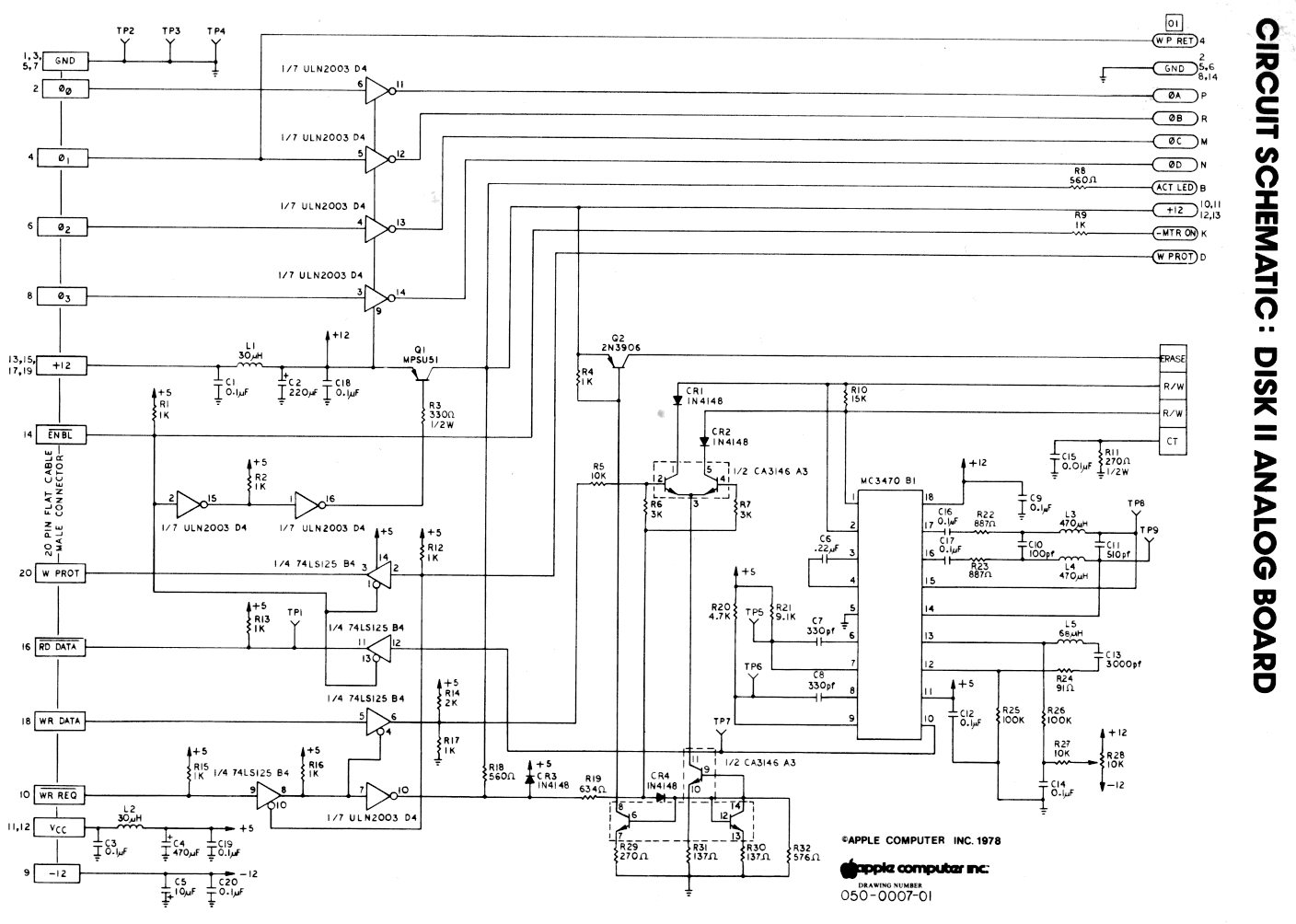
As best as I can tell, if the -12V supply voltage is incorrect, it will result in “peak shift”. The boundaries between bits will appear to shift slightly forward or backward from where they’re actually located on the disk. A small degree of shift won’t cause any problems, but eventually it will reach a threshold where bits begin to be read incorrectly, resulting in errors.
For the past week I’ve been researching and discussing current limiting circuits, current mirrors, and supply switching circuits. Can I forget about all that stuff and simply put a 1.8K resistor in series with the -12V supply? These test results say “yes”, but I’m still somewhat hesitant.
Hesitancy #1 is because I don’t know what the worst case might be. Maybe my Disk II drive isn’t representative of others. Maybe there are other types of drives (DuoDisk? Two daisy-chained Unidisk 5.25 drives?) that use the -12V supply in ways I don’t know about, or that will result in bigger voltage errors for the same series resistance.
Hesitancy #2 is because even if it works in tests, any error in the -12V supply voltage will cause some amount of peak shift, which might be the difference between a badly-degraded floppy disk working and not working. It’s a little like throwing away part of the noise margin for digital signals. It may still work fine for most situations, but when things are already working poorly for other reasons, it could be enough to tip the result into failure.
On the other hand, maybe the simplest solution is best. If it works in tests, even with series resistor values far larger than the ones I’d actually need for current limiting, then what’s not to like about this solution?
Read 7 comments and join the conversation