Retro USB Improvements
Some good news for Retro USB this week: new hardware, international keyboard improvements, and an enclosure prototype! Everything is maturing nicely, thanks to feedback and assistance from some helpful early adopters. More hardware is available, if you haven’t yet gotten yours. Forward ho!
For anybody who’s newly tuning in, Retro USB is an input converter for USB and ADB keyboards and mice. It works in two directions, connecting modern USB peripherals to a classic ADB-based Macintosh or Apple IIgs computer, or ADB peripherals to a USB-based computer running Windows, OSX, or Linux.
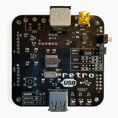
Board Version 1.2
After a slightly bumpy start, I’ve finally perfected the PCB design with version 1.2. This is the first version whose assembly won’t require me to apply manual fix-ups for my design mistakes, so the assembly process can be simpler and faster. It doesn’t make any difference to the final product, but hand-soldering patch wires and extra resistors is tiresome work. I’m very glad to be rid of that job.
![]()
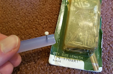
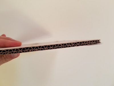
The most significant change in board version 1.2 is the addition of a 1000 uF bulk capacitor for the USB power supply. This enables Retro USB to handle brief spikes in power demand from attached devices, such as the spikes from an Apple A1243 keyboard during its initialization. With this capacitor, there are no problems with “spiky” USB devices like the A1243. The built-in hub on the A1243 works too, and is a convenient spot to attach the mouse.
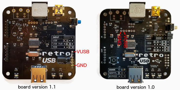
A bulk capacitor can be retrofit to board versions 1.0 and 1.1, if you’re comfortable with some basic soldering. You’ll need a capacitor of 680 uF or more, with a voltage rating of 6.0 volts or more, like this example. Solder the capacitor’s negative terminal to the board’s GND and the capacitor’s positive terminal to the board’s VUSB. See the photos for the board locations to use.
International Keyboards
Firmware version 0.1.15 resolves a few remaining issues for non-US keyboards, and layouts from French to Danish to Estonian and everything in between should now be working, in both USB-to-ADB and ADB-to-USB directions. Please see the International Keyboards section on the main Retro USB page for important details.
For correct key mapping with non-US keyboards:
- Choose the appropriate keyboard type in your operating system’s keyboard control panel or language preferences
- Set Retro USB to ISO mode (automatic for many keyboard models)
For many countries outside the USA, the USB keyboards designed for Windows PCs have a different layout than Apple keyboards. These PC-type USB keyboards may be used, but key mappings for some symbols will be incorrect where differences exist between the Apple and PC-type layouts. Best results will be obtained with Apple-brand non-US keyboards, or any brand US-layout keyboards.
Other Firmware Improvements
See the change notes included with the latest firmware for a complete list of what’s new. Here are the highlights:
- Right mouse button now works on NeXT computers
- Resolved an issue that prevented ADB keyboard capslock from functioning with macOS Sierra
- Fixed the output from help commands to appear correctly when using a non-QWERTY keyboard
- Fixed missed ADB keyboard events if the mouse is moved while typing
- Fixed device initialization when using multiple cascaded USB hubs
- Added new help command Control-Shift-Capslock-G to show the current keymap type
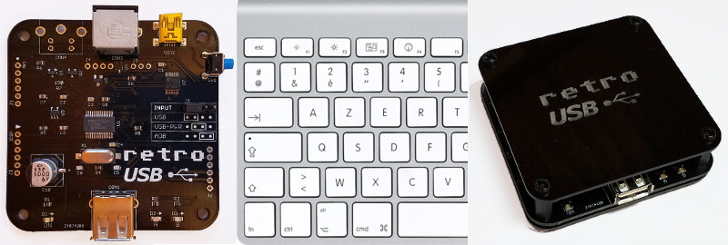
Enclosure Prototype
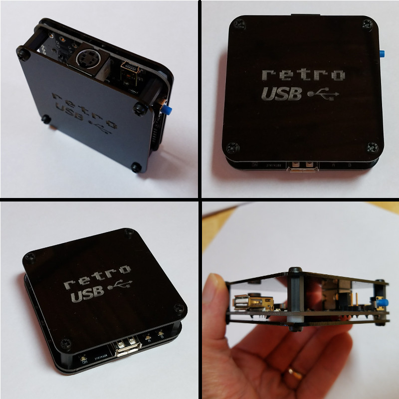
I’m working on a simple enclosure to protect the Retro USB board and add a touch of style. It’s gloss black 1.5 mm acrylic with an engraved logo, and cut to the same shape as the PCB. Add a few spacers and screws, and it makes a nice little package that’s easy to assemble. Initially I’d planned to make a fully-enclosed 6-sided box, but I would have needed to lose the rounded corners, and my experience with the Floppy Emu enclosure has taught me that 6-sided laser-cut enclosures can be awkward to put together. I quite like the appearance and simplicity of this enclosure, and it will probably show up in the store soon.
What’s Next?
Although the start was a little chaotic, Retro USB’s software and hardware now are both looking good, and the device can truly deliver on its plug-and-go promise for ADB and USB conversion. On the software side I’ll be looking at multi-button mouse support soon, so stay tuned for that. For the hardware, most of the effort will go into improving the assembly and testing process, and transitioning away from hand assembly. After that, we will see what else takes shape!
Read 1 comment and join the conversationBuild an Electric Scribble Machine
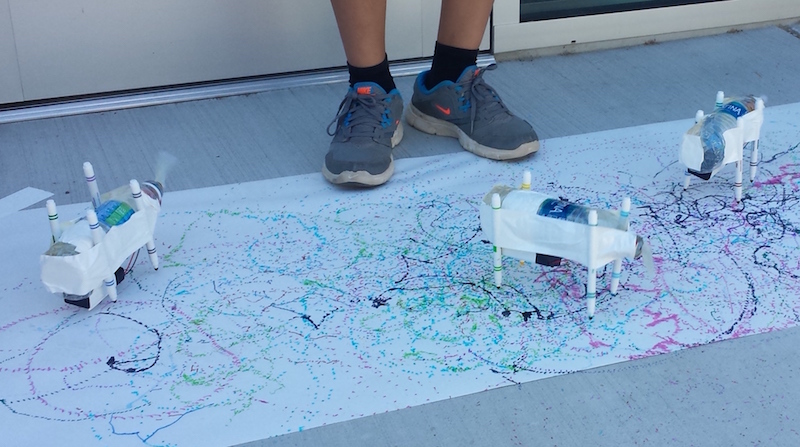
Looking for a creative project for kids to build? The Electric Scribble Machine is an entertaining device that’s easy to build from common parts – great for a scout troop project, school science fair, or just a lazy afternoon at home. For the past several years, as part of our local elementary school’s annual Discovery Day, I’ve led groups of kids ages 7-11 through the construction of a scribble machine. Tomorrow will be my last turn at Discovery Day, so I’m documenting the scribble machine design here for reference.
The basic concept is simple, and is borrowed from an Exploratorium design:
- An off-center weight on an electric motor will cause it to wobble and vibrate
- Mount the wobbly motor to a body made of plastic, cardboard, recycled bottles, or whatever’s available
- Attach colored felt-tip markers to the body to create legs
When the machine is placed on a large sheet of paper, it will wobble and jump around erratically, drawing interesting patterns as it moves.
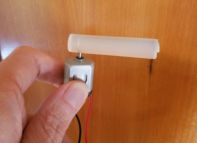
Step 1 – Motor
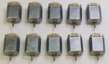
I use cheap DC hobby motors rated for 1.5V to 6.0V. They work fine with just a single AA battery, but are better with 2xAA batteries.
Step 2 – Off-Center Weight
Anything that can be mounted onto the motor’s shaft will work. The more unevenly the weight is distributed, the better. I’ve found that glue sticks for hot glue guns work nicely, and are easy to mount thanks to their texture.
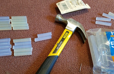
I use generic 4 x 0.44 inch glue sticks, and cut them in half with kitchen scissors to make 2 inch sticks. I hammer in a finishing nail near one end of the stick, then pull out the nail, leaving a small hole behind. The hole makes it easy to press-fit the glue stick onto the motor shaft without any additional tools: just push the shaft into the hole. The rubbery texture of the glue stick holds the shaft tightly, so it won’t easily pull loose.
Step 3 – Battery Holder (optional)
A 2xAA battery holder with an integrated on-off switch helps to create a reliable finished project. In the first years of building scribble machines, I held the motor wires directly to the battery terminals with rubber bands. It worked, but was a constant source of frustration when the wires came loose.
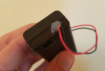
I’ve found that the wires on cheap battery holders are often poor quality, and break easily. Last year, about half of the battery holder / motor units suffered some kind of wire breakage during the day, leading to a lot of unhappy kids and emergency solder repairs. This year, I’ve added a drop of hot glue to the outside of each battery holder at the point where the wires exit. I’m hoping this will serve as a strain relief, and help reduce the number of broken wires.
Step 4 – Soldering (optional)
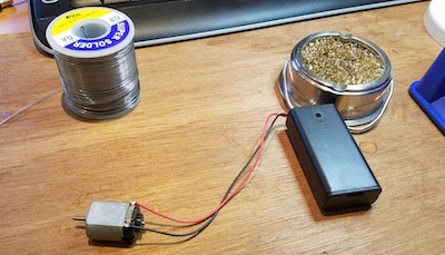
For the most reliable results, the battery holder wires should be soldered to the motor terminals. This is as easy as soldering gets, and it takes only a few seconds. A $15 Radio Shack soldering iron will do the job nicely.
As an alternative to soldering, the battery holder wires could be twisted around the motor terminals with pliers. There’s normally a small hole in the center of each motor terminal, which makes the job fairly easy.
Step 5 – The Body
Here’s an opportunity to get really creative – the body can be made from virtually anything! Try empty water bottles, plastic baskets, DVDs, cardboard, foam board, or whatever else might be handy. In past years I used empty plastic water bottles, sometimes with a few rocks inside to act as ballast. The plastic bottles work fairly well, although they do sometimes get partly crushed by kids who are overzealous in their construction efforts.
This year I’m trying something new: flat cardboard bodies, with holes drilled for the motor and felt-tip markers. It’s definitely possible to create these from old cardboard boxes, but cutting and drilling is time-consuming and tedious when making more than one or two. I took the easy path, and got squares of laser-cut double-thickness cardboard made by a local service. They were only 84 cents each, and the precise cut-outs for the motor and markers make it easy to snap the components into place. I added eight holes for markers, so the kids can experiment with different placements.
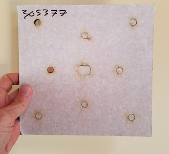
You’re welcome to use my laser-cut design. The Ponoko service will make them for you, if you add the design to your “personal factory” and select a material. Mine were cut from double layer corrugated cardboard, 6.7 mm thickness, 181 x 181 mm size (Ponoko’s standard P1 size).
Step 6 – The Legs
The legs of the Electric Scribbling Machine are generic colored felt-tip markers. Many parents already have dozens of these stuffed into every odd drawer and closet. Washable markers are nice for recovering from accidents, but not required. I used this cheap 30-pack of fine tip markers.
Three legs or four? I’ve tried both, but usually go with four. The design of the scribble machine requires some fine-tuning of stability, and four legs create a more stable base than three. Too much stability isn’t necessarily a good thing, however, since a certain degree of wobbling is required to make a good scribble design. But a high degree of wobbling will quickly lead to wild gyrations, and then the machine will topple over in a sad pile. It takes a few minutes of experimentation with leg lengths and ballast weights to find a happy medium.
Step 7 – Assembly and Use
I normally prepare the battery packs, motors, and glue sticks ahead of time. On the day of the event, the kids combine these with the batteries, body, and legs to assemble a finished machine. It sounds simple, but the assembly process always seems to require a surprisingly large amount of time, usually 30 minutes or more.
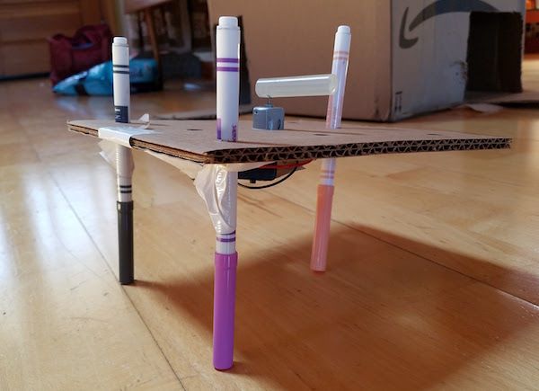
Duct tape, masking tape, rubber bands, or hot glue can be used to mount the motor and battery pack onto the body. These are the heaviest components, so it’s best to place them near the center of the body. I’ve found that most 7 to 11-year-olds don’t have the physical dexterity to work with rubber bands, so duct tape is my preferred adhesive method. After mounting the motor and battery, the legs are attached the same way. The caps on the markers add about 1.5 inches to their length, which needs to be considered while mounting them, otherwise the finished machine will sit too low to the ground when the caps are removed.
After watching the machine scribble random designs for a while, it’s time for some directed experiments.
- What happens if one leg is a different length than the others?
- What’s the effect of moving the legs closer to or further from the body’s center of mass?
- Can you configure the machine to wobble forward in a straight line instead of gyrating randomly? Try racing them.
- Reconfigure the motor to lie on its side, spinning the weight in the vertical plane. How does the machine’s motion change?
- Decorate the bodies with stickers and give them cool names.
Shopping List
Supplies for 30 kids:
30 electric motors $45.00
15 hot glue gun sticks $8.69
30 battery holders $24.36
60 AA batteries $11.87
30 laser-cut cardboard bodies $25.20
100 colored markers $17.44
The total cost is about $132, or $4.42 each.
If you build an Electric Scribble Machine, send me a note and tell me how it went!
Be the first to comment!Retro USB 1.1 Fail
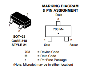
I received a large number of new Retro USB PCBs today, which include a few small component changes from the 1.0 design. Bad news: I blundered by reversing the gate and drain connections on the MOSFETs used for level conversion. DOH!! Always read the datasheet carefully, boys and girls. On a 3-pin device, I must have assumed the gate would be the pin on the side by itself, with drain and source paired up on the other side, just like the canonical drawing of a transistor. Unfortunately that’s not true here. Hopefully I can find another brand of SOT-23 N-channel MOSFET whose pins are organized the way I thought they should be, or else this whole pile of PCBs is going into the trash. For a moment I thought maybe I could rotate the MOSFET 120 degrees, or even mount it upside down, but I don’t think any soldering tricks can save me.
Read 5 comments and join the conversationFloppy Emu Back in Stock

After a few weeks of scarcity, more Floppy Emu hardware is again available at the BMOW store, hot off the courier truck. It’s always my goal to keep a steady inventory available, but that’s proven more difficult than I imagined. The trouble isn’t surges in demand, or assembly problems, but just managing the supplies of all the materials involved.
To sell one Floppy Emu, I obviously need to have a main board in stock. But I also need the DB19 adapter board, which is a separate part. And I need 20-pin ribbon cables. And SD memory cards. And acrylic cases from the laser cutter. And padded mailers, boxes, bubble wrap, and postage labels. Sales grind to a halt when I run short of any of those supplies. To get them at reasonable prices requires buying them in bulk, with delivery times ranging from a few days up to two months. I can’t just drop into the corner store to buy more when I run low.
Maintaining those supplies efficiently can be challenging, and it’s not something I do very well. Real companies have automated inventory management systems that automatically order more parts as needed. I just glance into a box now and then, and maybe order more supplies if the pile looks small and I’m not busy doing something else. In this case I didn’t begin the hardware assembly process soon enough to account for the long lead time. I still had lots of hardware on hand when I reordered more, but it was all gone two weeks before the order was fulfilled. It’s one more thing I need to learn to do better.
Read 1 comment and join the conversationRetro USB Firmware Update 0.1.8
Firmware version 0.1.8 is now available from the Retro USB page. This version adds several improvements:
0.1.8
- Added support for ISO keyboards, commonly used outside the USA. This should fix the key mapping for the ^ or @ key (the key to the left of 1) and the <> key (the key to the right of the left shift). Mostly untested since I don’t have any ISO keyboards.
- Keymap type can be cycled between ANSI, ISO, and JIS (currently non-functional) with the new help command Ctrl-Shift-Capslock-T
- The keymap type is automatically set to ISO at startup if an Apple-brand ISO keyboard is detected (untested). If you have a non-Apple ISO keyboard, you’ll need to switch to ISO manually with Ctrl-Shift-Capslock-T.
- Single-function USB devices are now prioritized over composite devices. Prevents a mouse with a keyboard macro feature from usurping the role of keyboard.
- New help command shows the USB vid:pid or ADB handler ID of the keyboard and mouse: Ctrl-Shift-Capslock-I
- Disabled HID report descriptor parser’s error check for report items with count = 0. Some real USB devices do this, like the Logitech RX 250 mouse.
- Added 250ms delay at startup in ADB-to-USB mode, before attempting any external communication
If you have an ISO keyboard, and you’ve previously used Retro USB with firmware earlier than 0.1.8 on an OSX Mac, you’ll need to delete the OSX keyboard preferences to make it “forget” Retro USB. Delete the file /Library/Preferences/com.apple.keyboardtype.plist, then restart. If you don’t do this, your key mappings may be incorrect.
0.1.7
- Permanently enables USB composite device support
- Increases mouse speed by 20% in USB-to-ADB mode
Retro USB is an input converter for USB and ADB keyboards and mice. It works in two directions, connecting modern USB peripherals to a classic ADB-based Macintosh or Apple IIgs computer, or ADB peripherals to a USB-based computer running Windows, OSX, or Linux. The foreign keyboards and mice behave exactly like native peripherals, requiring no special software or drivers – just plug it in and go.
Be the first to comment!USB Voltage Sag
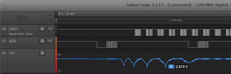
I received a couple of reports that Retro USB doesn’t work correctly with the Apple Aluminum Keyboard, model A1243 and its smaller sibling A1242. This is Apple’s standard wired USB keyboard, so it’s fairly common. The A1243 has an integrated hub with two USB ports for other devices. I don’t have one myself, but I was able to borrow an A1243 from a neighbor so I could take a look. What I found was not good.
During the USB enumeration process, there’s a huge voltage sag on the VUSB +5V supply. This is true whether VUSB is fed from the Macintosh’s ADB +5V supply, or from an external 5V supply. During USB enumeration, VUSB abruptly drops from 5V down to about 2.7V over a period of half a millisecond. Then it recovers, drops again, and repeats the process three or four times. Meanwhile the microcontroller starts reporting USB “bus turnaround” errors. Eventually the voltage bouncing stops after about 6 ms, but the keyboard never enumerates successfully.
At first I thought this was a simple problem: I just needed a bigger capacitor on VUSB. When the A1243 enumerates, it must switch on some internal power-hungry circuit that momentarily draws a lot of current, dragging down VUSB. The Retro USB board has a single 10 uF ceramic capacitor on the +5V USB supply. But when I tried larger capacitors up to 220 uF, they barely made a dent in the degree of voltage sag. With the 220 uF cap, the voltage sags bottomed out at 3.4V instead of 2.7V, but I still got lots of USB errors and failure to enumerate. 220 uF is already a jumbo-sized capacitor, and I can’t imagine fitting something even larger on the Retro USB PCB.
My second thought was to add an inline inductor between the VUSB supply and the USB connector. That would prevent too much current from being drawn all at once. I only had a single suitable inductor on on hand, with an uncertain value: the bag said 22uH, but the component was labeled 223 which I believe means 22mH. At any rate, it didn’t help much, and VUSB still sagged down to 3.2V while the keyboard failed to enumerate. With failures of both the capacitor and inductor techniques, I’m out of other ideas for ways I can minimize or eliminate this VUSB sag.
But wait, there’s more to this mystery. The A1243 actually enumerates OK, with no VUSB sag at all, if nothing is connected to its USB ports. It’s only when a mouse or a flash drive is connected to the A1243 that the big voltage sag occurs. And these same mice and flash drives don’t cause any voltage sag when they’re connected through a different unpowered hub. I’ve come to the conclusion that the A1243 contains a big capacitor that only gets charged during USB enumeration, and only if something is connected to one of its hub ports, so that the hub function is enabled.
I was sometimes able to get the A1243 with an attached mouse to enumerate successfully, if I powered the Retro USB board from an external 5V supply instead of the Macintosh ADB 5V supply. The same degree of voltage sag was still there, so I’m not even sure why it worked, and success seemed to depend on exactly which mouse I tried.
The A1243 also causes problems in other scenarios, even where no voltage sag is observed. It works OK when it’s connected through a separate unpowered hub. But if a mouse is also connected to that same hub, there’s no voltage sag, but there are large numbers of USB errors and none of the devices ever enumerate successfully.
There’s clearly something strange about the A1243’s power requirements, as evidenced by this Apple forum thread full of complaints. A hundred people all agree that their computer wasn’t recognizing their A1243 anymore, until they used the USB extension cable that’s bundled with the keyboard, then it magically began working again. A few people said a 3rd-party USB extension cable also solved their problems. It sounds bizarre, but if the extension cable is acting as a small source of additional inductance and capacitance, I could imagine it having a beneficial effect. However, when I tried using the extension cable with Retro USB and the A1243, the voltage sag was still just as bad and the problems remained.
If the A1243 weren’t such a common keyboard, I’d simply write it off as an unknown incompatibility. But given how common this keyboard is, I really want to find a way to make it work.