

DB-19: Resurrecting an Obsolete Connector
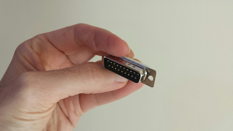
Oh man, this is good! You’re looking at the first DB-19 connector to be made in the 21st century:
This is a happy story about the power of global communication and manufacturing resources in today’s world. If you’ve been reading this blog for any length of time, then you’ve certainly heard me whine and moan about how impossible it is to find the obscure DB-19 disk connector used on vintage Macintosh and Apple II computers (and some NeXT and Atari computers too). Nobody has made these connectors for decades.
I’ve got a disk emulator product called Floppy Emu that attaches to an Apple DB-19 port, so I need a steady supply of these connectors to build my hardware, and that’s a problem. Over the past couple of years, I’ve scrounged what seems like every warehouse and basement on the planet, and bought up nearly the entire world’s remaining supply of new-old-stock DB-19 connectors. My last few product batches included DB-19s from some very obscure international sources. It was clear I’d reached the end of the road.
This wasn’t a surprise. The DB-19 shortage first became obvious to me about a year and a half ago, when a manufacturing error forced me to replace all the DB-19 connectors in a batch of boards, and replacements couldn’t be readily found. Since then I’ve written a dozen times about the impending DB-19 doomsday. I also made several attempts to design a DB-19 substitute using a small PCB and suitably-arranged header pins, but while they more-or-less worked, I wasn’t satisfied with the result.
The specific part in question is a D-SUB DB-19 male solder cup connector, sometimes called DB-19P. It’s very similar to the more familiar DB-9 (old style serial ports) or DB-25, but with a different width to accommodate the different number of pins. “But wait!” says the well-intentioned blog reader, “this web site over here has DB-19P connectors for sale right now!” They may claim to have them, but trust me, they don’t. Electronics parts suppliers seem to make a habit of listing available items that aren’t actually available, whether out of laziness or as an intentional bait-and-switch, I’m not sure. But if you call them or try to actually order the parts, you’ll find they don’t exist.
Custom Manufacturing
About 15 months ago, I first started looking into the idea of manufacturing new DB-19 connectors. So here’s the thing – how do you go about having something like this made? I had no clue, and it took me over a year. How do you find factories that might possibly build something like this, and then how do you find a contact person to whom you can explain your needs? Almost all the manufacturers that I talked to blew me off, or wouldn’t even talk to me at all. The US-based manufacturers weren’t interested, or couldn’t do it. In the end, I went through Alibaba listings for companies that make other types of D-SUB connectors, and emailed several dozen of them to ask if they could make a DB-19. Only a few even replied, and only two said they could, both located in China.
The estimated cost was eye-watering – a minimum order size of 10000 pieces and a total cost well into five figures. I had naively assumed that somebody might still have old DB-19 molds they could reuse, or that DB-25 tools could somehow be easily adapted to make DB-19 connectors. Nope. I did a lot of research into possible alternatives like 3D printing or alternate materials, but nothing looked viable. And given the tiny scope of my disk emulator business, I couldn’t justify spending tens of thousands of dollars for making new DB-19s.
So nothing happened. A year passed, and the DB-19 shortage grew more dire still. I made another attempt at designing a DB-19 substitute, but wasn’t satisfied with the results. Out of options, I reluctantly circled back to the manufacturing idea again. I tried to calculate how many years of future sales it would take before I could earn back my investment, and it was a depressingly large number.
But just as I was getting discouraged, good luck arrived in the form of several other people who were also interested in DB-19 connectors! The NeXT and Atari communities were also suffering from a DB-19 shortage, as well as others in the vintage Apple community, and at least one electronics parts supplier too. After more than a year of struggling to make manufacturing work economically, I was able to arrange a “group buy” in less than a week. Now let’s do this thing!
Let’s Build It!
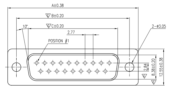
Early on, it became clear they’d need more specific directions than simply “make it like a DB-9 but with more pins.” They wanted mechanical drawings and specifications for the part. Umm… They asked for information from my engineering department. Er… I was stumped by this for a short while, but then I found an old mechanical drawing of a DB-25. I photoshopped that sucker, edited some key measurements, and that was what they used for the very expensive mold-making process. I’m still kind of shocked that this actually worked.
Payment required wiring a Very Large Amount to a bank in Hong Kong – no PayPal accepted here. I’m sure the people at my bank thought I’d been duped by some kind of Nigerian 419 scam. Maybe it’s more common elsewhere, but transfers of this type are rare at US retail banks. In my case, it took the branch manager and 30 minutes of paperwork to get the transfer done.
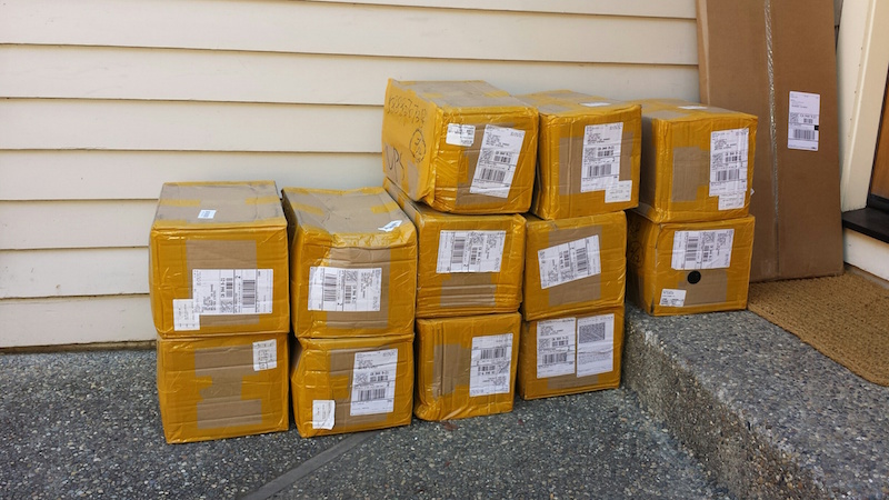
Two months passed, and a round of prototyping. Progress was slow but steady, and I received updates from the manufacturer every few days. I kept waiting, eagerly anticipating this DB-19 bounty. At the end of May the product finally shipped, only to disappear into a US Customs black hole somewhere for a couple of days. Then at long last, after what felt like an infinite wait, I came home to find 10000 of these beauties stacked on my doorstep:
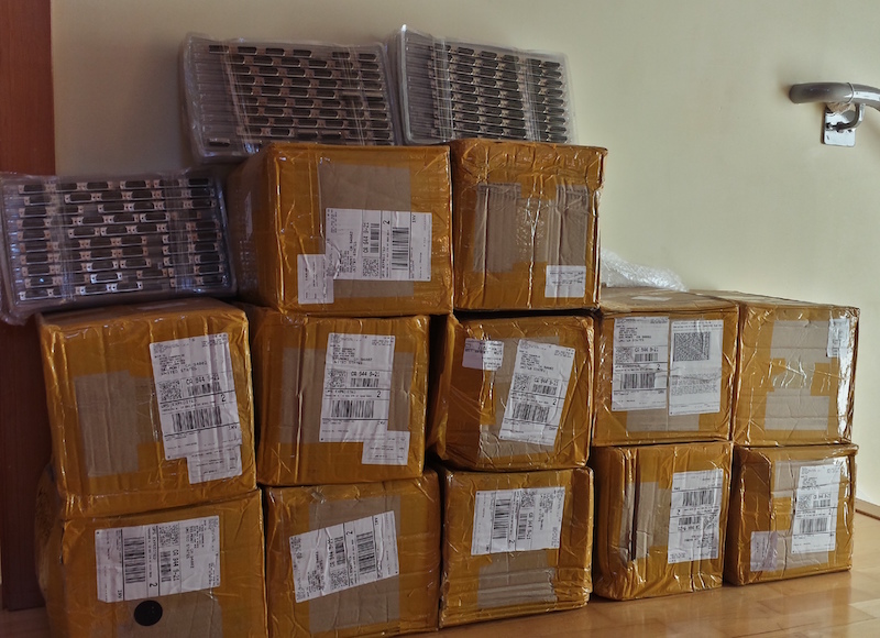
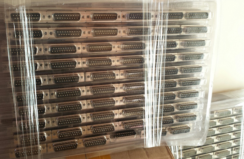
For the moment at least, I have nearly the entire world’s supply of DB-19 connectors, stacked in my living room. I think I’m going to fill the bathtub and swim in them.
Next step: re-ship the majority of these DB-19 connectors to the other people in the group buy. They should start becoming available in small quantities at electronics parts suppliers in a couple of weeks.
Assuming Floppy Emu sales continue apace, I’ll eventually make back my investment in a couple of years. If not, it will at least make for a good story. 🙂 Now, let the retro-hardware celebration begin!
Read 65 comments and join the conversationDirty PCBs Review
Today’s electronics hobbyists are blessed with many options for custom PCB manufacturing, like Seeed, Elecrow, and OSH Park. For around $1 to $2 per board, depending on size and quantity, these vendors will turn your EAGLE or KiCad or other Gerber files into shiny new PCBs. I’ve used all three in the past, but my go-to vendor for most things is Seeed.
Dirty PCBs is a newer entry in this space, but it’s affiliated with Dangerous Prototypes, who are long-time members of the hobbyist electronics community. A few years ago Ian Lesnet moved himself and the company to Shenzhen, China, and Dirty PCBs is sort of a matchmaking service between Shenzhen PCB manufacturers and hackers around the world. For a recent PCB purchase of 20 boards, I decided to give them a try.
Saving Pennies
The main attraction of Dirty PCBs is the price. Even among other cut-rate PCB manufacturers, it stands out as the cut-ratest. Any color PCB is available for the same cost, whereas most manufacturers charge extra for colors other than green. Slow-boat shipping is free worldwide, and the faster shipping options tend to be cheaper than at the competition. For my order of 20 red PCBs, 10×10 cm size, shipped by DHL China, here’s how Dirty PCBs compared to Seeed:
10×10 cm PCB @ qty 20 = $57.43
Red soldermask = $10.00
DHL shipping to USA = $24.71
TOTAL = $92.14
Dirty PCBs
10×10 cm PCB @ qty 20 = $50.00
Red soldermask = $0.00
DHL shipping to USA = $15.00
TOTAL = $65.00
Dirty PCBs also uses a constant price per board as you increase the quantity, or offers a small discount for larger quantities, as you would typically expect. Seeed has the bizarre habit of offering a negative “discount” for higher quantities. E.g. with Seeed it’s sometimes cheaper to buy 10 boards twice than to buy 20 boards.
Ordering
My biggest gripe with Dirty PCBs is the website itself and the way it’s marketed. The site’s tagline says “No bull, just crappy PCBs.” I suspect I’m in the minority, but I just don’t appreciate the joke here. Call it basic, no-frills, or rock-bottom if you like, but please don’t tell me I’m paying money for something that’s intentionally crappy. Especially when, if you read the specs and the terms, it’s not crappy at all. Yet I’m somehow left with a mental picture of a sloppy, careless, and all-around half-assed manufacturing process. I don’t think it’s accurate, but that’s the image it paints in my mind.
To be fair this attitude is intentional, and can be traced to the “accidental” launch of the Dirty PCBs service. As Ian tells it, he never meant to launch a PCB service, but simply hacked together some scripts for the convenience of his friends. That unofficial “for friends” service became unexpectedly popular, and Dirty PCBs was born. Ian’s said in the past that the service doesn’t really make any profit, so his tolerance for whiners and time-wasters is low. To quote the About page:
This site was intended for friends and not the public. We’ll process your boards, but we only make about 30 cents per order. We really don’t care if you want to take your business somewhere else, and it’s not worth our time to deal with stupid questions or asshats. Paypal fee reversals, annoying emails and the like will get you banned from the site.
Fair enough, and +1 for use of the word “flippant”. The actual ordering process was simple, except for a mistake I made when uploading the Gerber files. The upload button doesn’t mention what file format it expected (I later found this information on the About page), so I uploaded a zip archive of the same Gerbers I would normally send to Seeed. It appeared to work, and I went through the entire checkout and payment process, only to be informed after I’d paid that no board outline file was found. This was because my Gerbers had different filename extensions than Dirty PCBs was expecting. After renaming the files and uploading a new zip archive, all was well.
Delivery
My order was placed on Thursday afternoon, and the finished PCBs were in my mailbox on the following Wednesday afternoon. Six days! That is crazy fast. Maybe I just got lucky and hit the manufacturing cycle at the perfect time, but that’s more than twice as fast as any other PCB order I’ve ever made in China or the USA.
Inside the box was an unexpected surprise – 23 PCBs instead of 20. I know the Dirty PCB’s proto-pack is “about 10” and often 11 or 12, but I didn’t realize they did a similar thing for larger orders. Presumably they make 10% extra in case some PCBs fail the e-test, then mail you all the boards that passed testing. So hey, three extra free boards. Thanks!
Inspecting the Boards
Now for the key question: were the boards any good? From my inspection, I’d say mostly yes. I spent a long time examining the boards under 10x magnification, and comparing them to my original EAGLE files, and to the Gerbers using gerbv. Probably I’ve never examined any PCB quite so intensely, and some of the issues mentioned below may be typical of other discount PCB manufacturers too. For the money paid, I’m not complaining, but for completeness I’ve catalogued the good and the not-so-good.
The Good
First and foremost, my sample PCB worked great once I populated the components and put everything together. This is about the only thing that really matters in the big view, and it means there were no accidental shorts or breaks in the PCB traces. Of course I hadn’t really expected any problems there, since Dirty PCBs advertises a minimum 5 mil trace/space size, but I only went down to 8 mil and was nowhere near the limit.
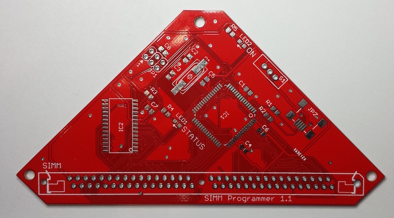
My board is a rather funky hexagon shape, or a triangle with clipped corners if you prefer. There were no problems routing this non-standard board outline.
When examined under magnification, all the drill holes appeared nicely centered in the vias and pads. The edges of traces and planes appeared clean and crisp. Silkscreen was sharp and nicely legible. The soldermask was a nice bright red color, and tented vias were actually tented.
The Not-So-Good
One small gripe: the silkscreen layer was slightly offset from the copper layers and drill holes, as you can see in the photo below. The silkscreen outline for this AVR ISP footprint isn’t centered around the pads. This doesn’t matter much, but it may bother you if you’re a stickler for little details.
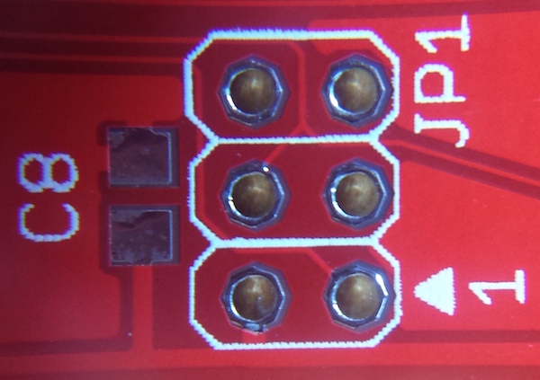
One bigger gripe, that I’m still not sure is my fault or Dirty PCBs’ fault: some of the extra-large vias appear either larger than intended, or not in the right place – it’s hard to be sure which. Here’s an example of a large untented via that connects ground planes on the top and bottom of the board. In the photo, notice how the edge of the drill hole is almost exactly in line with the edge of the ground plane (which is partly obscured by the silkscreen line)? And the plating around the drill hole actually extends beyond the ground plane, bowing outwards slightly into the gap between the ground plane and the neighboring trace? And the stop area (the area without soldermask) extends nearly all the way to that neighboring trace?
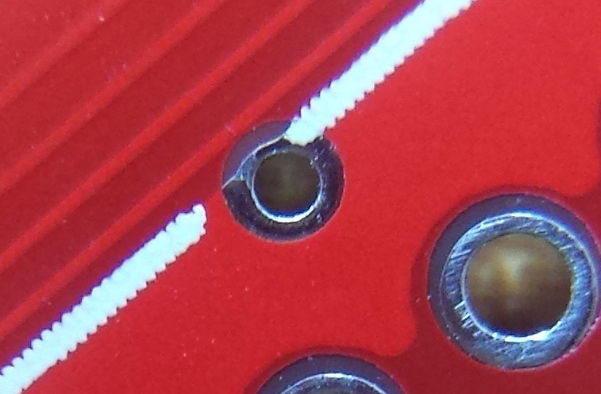
Here’s the same region viewed in EAGLE, with the silkscreen hidden. Notice that the drill hole comes well short of the ground plane’s edge, the plating around the hole doesn’t extend beyond the edge, and the stop area only extends maybe one-third of the way into the gap between the ground plane and the neighboring trace.

And here’s the same region once more, looking at the actual Gerber files with gerbv. The top copper layer is magenta, drill holes are lavender, and the stop mask is gray. Maybe the Easter Bunny chose this color scheme. Where layers overlap you’ll see additive coloring. There’s no separate color for the plating around the hole here, since both the plating and the ground plane are just part of the top copper layer. It almost looks like Dirty PCBs interpreted the stop mask layer (gerber.GTS) as an additional top copper layer, than generated its own stop mask around that.
Another possibility jumps to mind as I type this: I used a non-standard drill size for those extra-large vias of 0.02362205 inches – not sure how that happened. I wonder if DirtyPCBs rounded up to the next larger drill size, then automatically enlarged the copper area and stop mask to compensate. The through-hole pads in these pictures use a 0.040 inch drill, so the ratio of the hole sizes should be 0.02362205 / 0.040 = about 0.59. But measuring the actual hole size ratio observed in the PCB photo, it’s about 0.62. So those via holes are about 4.7% larger than they were intended to be, if my figuring is correct.

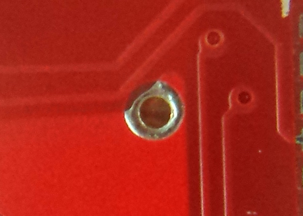
Here’s another example of the same issue. This via bulges outward slightly from the top-left of the ground plane, and the stop area extends all the way to the neighboring trace. But in the source file, the via’s drill hole and plated area are both completely within the boundaries of the ground plane, and the stop area only extends about a quarter of the way to the neighboring trace.
Overall Rating
As an overall rating, I’m giving Dirty PCBs a thumbs-up. They were cheap, super fast, sent me extra boards, and the boards worked. I’m not sure I’d trust them yet with a design that goes all the way to the 5 mil limit, but it’s probably best to avoid that limit anyway. I wish they’d change the name or at least the tagline, but that’s just me. I expect I’ll use Dirty PCBs again, and will report how it goes. Thanks for reading!
Read 6 comments and join the conversationDiscovery Day!
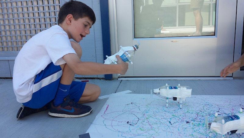
Every year I lead a group of kids in the construction of an “Electric Scribbling Machine”, as part of the local elementary school’s Discovery Day program. The program sessions are run by parents and local community members, and can be anything from karate to marshmallow cannons to frog dissection. The kids range in age from 7 to 10 years, and the sessions are only 50 minutes long, so it’s a challenge to design interesting projects to fit the available time and skill level of the kids. Despite the challenges, we always manage to have lots of fun!
The scribbling machine concept is simple:
- Attach an off-center weight to an electric motor, so it wobbles and vibrates
- Attach the motor to some kind of body
- Attach colored markers to the body as “legs”
- Set the machine on a large sheet of paper, and watch it go!
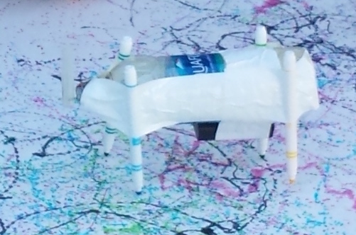
I use cheap DC hobby motors rated for 1.5V to 6.0V, with an AA battery. The off-center weight is a glue stick (designed for a hot glue gun), with a small pre-cut hole that press-fits onto the motor shaft. The body is an empty plastic water bottle, and the legs are washable Crayola markers. What could go wrong?
If you guessed there would be tons of problems, you’re right. In past years, we used rubber bands to hold the battery and legs to the body, and the motor wires to the battery. Kids and rubber bands don’t mix well in this project – most of them lack the physical dexterity needed to twist a rubber band around two objects and hold them in place. They struggle with it, accidentally crush the water bottle, and get frustrated. Rubber bands on the battery for the motor wires are also a problem. You can imagine how unreliable that connection can be, and there’s no easy on/off switch.
A New Design for 2016
This year we made two big changes to the design. I bought a pile of 2xAA battery holders with an integrated on/off switch, for a much simpler and frustration-free electrical connection. And I replaced all the rubber bands with duct tape. Who doesn’t love duct tape? With these changes, we were guaranteed a problem-free Discovery Day, right?
The battery holders were a clear improvement, and I was pleased with how they worked out. The duct tape was a mixed bag. It was certainly easier for the kids, and it allowed the legs to be attached in more orientations than are possible with rubber bands. But if you’re not the parent of an 8-year-old, it may be hard to appreciate just how big of a mess kids can make with tape. There were wads of snarled tape everywhere, and when someone wanted to un-tape a leg and make an adjustment, it was difficult.
I could live with snarled tape, but the bigger issue came from an unexpected source: the solder connections. Of 24 battery and motor packs, we had at least 12 that failed in various ways. Sometimes the wire broke off at the motor, and sometimes at the battery pack. This was a surprise, since we used the same motors soldered in the same way as previous years, where I’d only ever experienced one or two breaks before. During the first session, we went through all of the packs for that session and half of the packs intended for the second session. I raced home to get my soldering iron during the short break between sessions, and repaired as many packs as I could. In the end we had enough for everyone, but the fragility of the packs was surprising and frustrating for the kids.
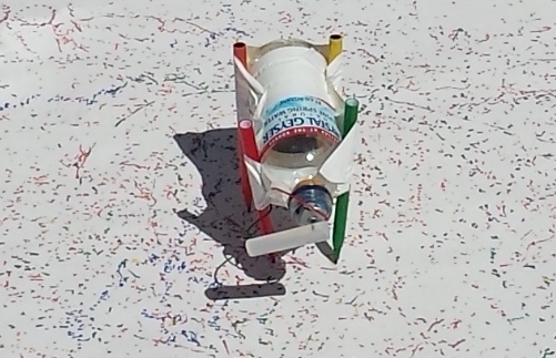
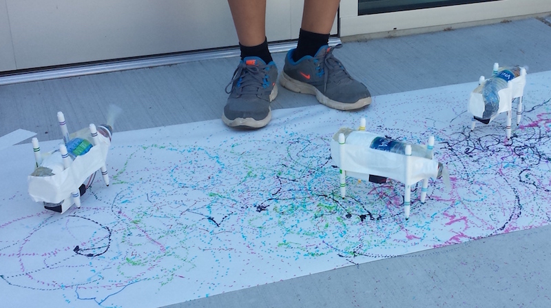
After the scribbling machines were more-or-less finished, it was great to see some of the kids experimenting with different designs. Longer or shorter legs, angled or straight, flat-footed or precariously balanced… each produced a different kind of motion in the resulting machine. Some spun in lazy circles, while others raced straight ahead like a car. All of them made interesting spiral and dot patterns on the paper as they went.
I believe I used the words “magnetic field” at least once during the session, so that counts as educational. Success!
AV2HDMI Video Adapter for Apple II
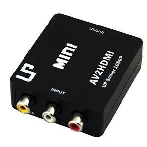
Many retro computers and game systems have a composite video output – the familiar round yellow plug. Unfortunately, composite video inputs are increasingly rare on modern TVs and computer monitors, creating a headache for retro enthusiasts. This is a mini-review of one solution to this problem: a composite video (and stereo audio) to HDMI converter box called AV2HDMI, which I purchased for $18 from Amazon.com.
Converting composite video to a more modern format is more difficult than it might first appear. It’s not merely a matter of physically converting one plug shape to another. Composite video is an analog signal that combines the color, luminance, and frame synchronization information all on the same wire. It comes in different formats like NTSC, PAL, and SECAM, which imply a different number of horizontal lines per frame and frames per second. The signal is also interlaced, meaning that the even lines are sent in one frame and the odd lines in the next frame.
A converter must detect the input format correctly, separate the color/luminance/sync info, deinterlace the lines, perform analog-to-digital conversion, upscale the resolution, and output a more modern VGA or DVI or HDMI signal. There are plenty of opportunities for things to go wrong and generate a poor quality result. It doesn’t help matters when the original composite video signal doesn’t quite meet the NTSC spec in the first place, as is the case for the Apple II series.
AV2HDMI
The AV2HDMI box that I purchased is one of at least 20 very similar items on Amazon, all with the identical case and connectors, but with different names, colors, and labels. It seems likely that these are all really the same device, with the guts manufactured by a single vendor, and then many other vendors packaging and rebranding it. The case is sealed tight, without any screws or other obvious methods of disassembly, so I couldn’t peek inside to learn more.
Previously I was using the composite video input on a Dell 2001FP LCD monitor, which seems to be known for good handling of composite video. But in an effort to declutter my desk, I really wanted to get my Apple II systems working with the primary Asus monitor that I also use for my PC and Macintosh work. Keeping around the Dell 2001FP just for occasional use was a hassle, so my main motivation in purchasing this converter was convenience rather than top-quality video output. I also wanted something that could work with any Apple II system, as well as old video game systems, rather than a solution that’s specific to any one model of Apple II.
The overall results from the AV2HDMI aren’t quite as good as the 2001FP, but they’re close, so I’m happy. I can’t decide if it’s stretching the 4:3 image to 16:9 or not – it seems maybe half stretched, like something midway between the two aspect ratios. It didn’t bother me. The output has very good contrast and color saturation. It’s also quite sharp, which isn’t necessarily a good thing. The 2001FP produces slightly fuzzier-looking output, which I think is more faithful to the appearance of an old-shool CRT, and helps make certain color-fringing artifacts less objectionable, but the difference is minor.
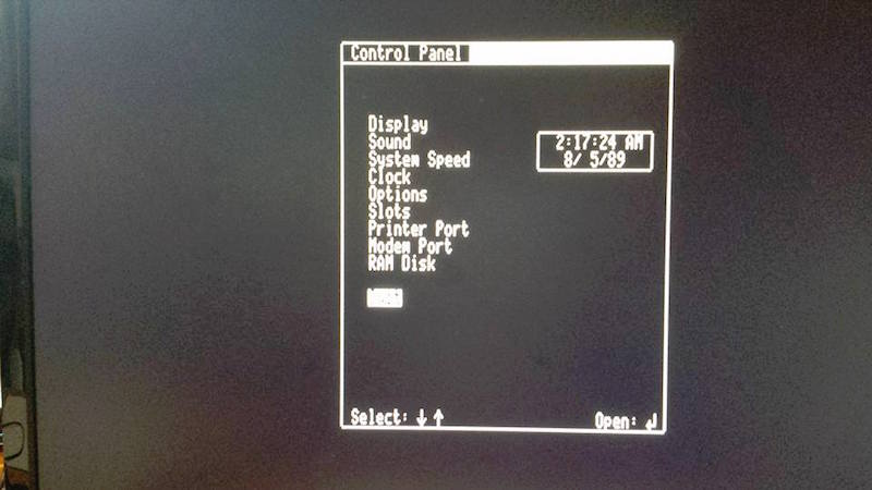
The AV2HDMI appears to have some kind of auto-configuring behavior, where it adjusts itself to the incoming video signal’s format, black levels, etc. This takes about two seconds, during which the image isn’t visible. Switching video modes on the Apple II (say between text and low-res graphics mode) forces a repeat of the auto-configure logic, so there’s a few seconds of black screen when switching modes. It’s a little bit annoying, but not too bad.
Testing
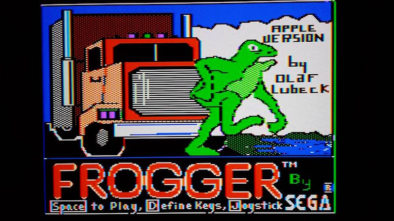
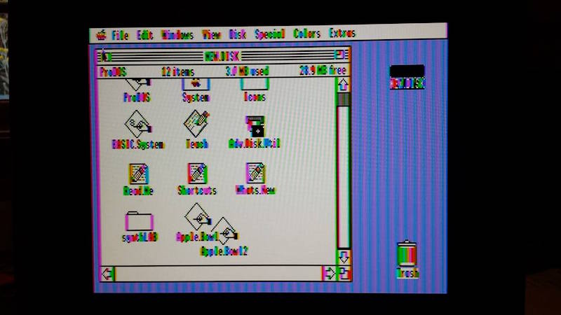
All of these tests but one were performed on an Apple IIgs. Pure text modes looked good in 40 and 80 columns, as did color games. The higher resolution GSOS desktop was acceptable in black and white, but suffered from minor shimmering and sparkle. GSOS in color was pretty bad, but remember this is still composite video, and GSOS never really looked very good on a composite monitor.
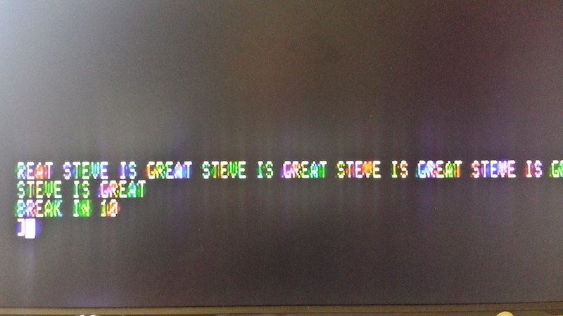
In the pure text modes, the computer disables the NTSC colorburst, which makes the monitor think it has a purely black and white video signal. This helps a lot, and results in a nice crisp image with the AV2HDMI. In low-res graphics mixed mode, with four lines of text at the bottom of the screen, the colorburst is enabled and the text looks markedly worse. Substantial amounts of green/purple fringing are visible on the edges of each text character. The 2001FP does a little bit better in this case, but still shows the same kinds of artifacts. I recall seeing those same green/purple artifacts back in the day, so I know they’re real and not due to some problem with the video conversion. I don’t recall them having been quite so dramatic as they appear now, but it’s been a long time.
AV2HDMI Photos
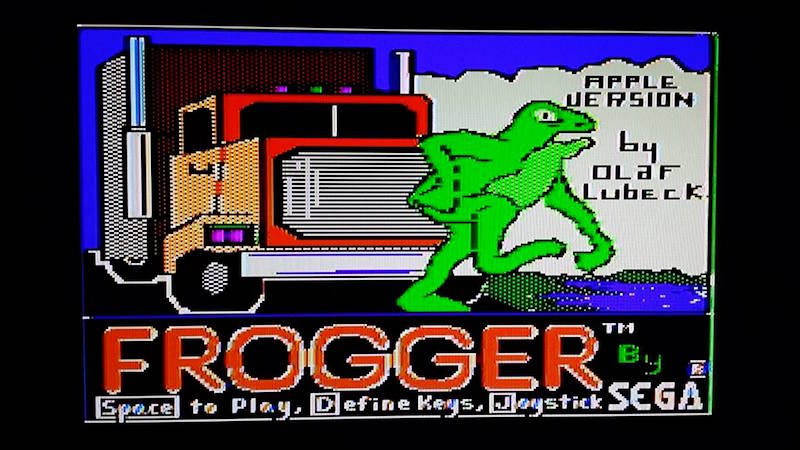
AV2HDMI color game
AV2HDMI pure text mode (80 column)
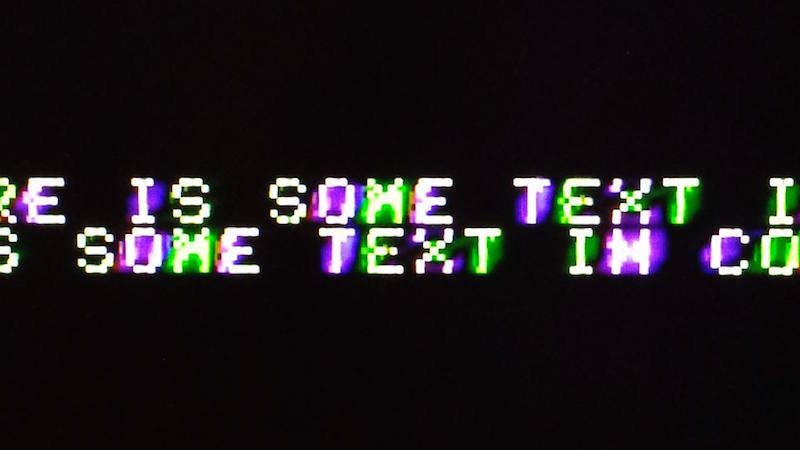
AV2HDMI mixed mode text close-up
AV2HDMI mixed mode text on Apple IIc
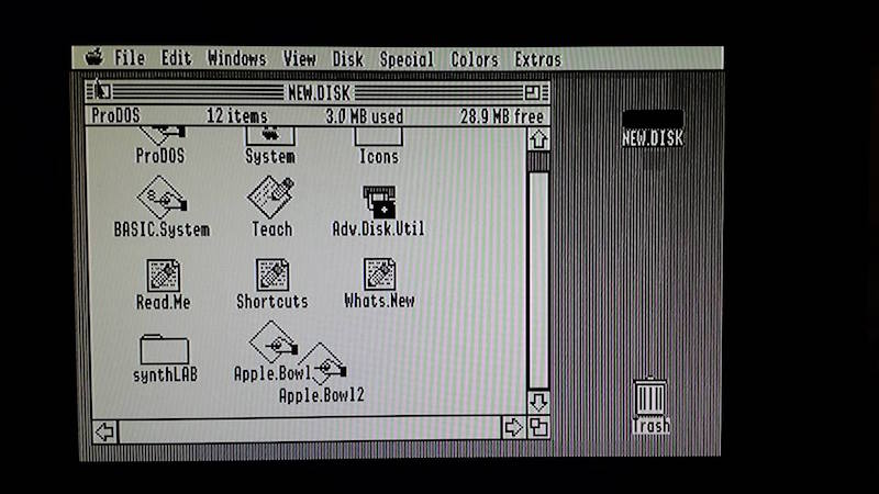
AV2HDMI GSOS desktop, monochrome mode
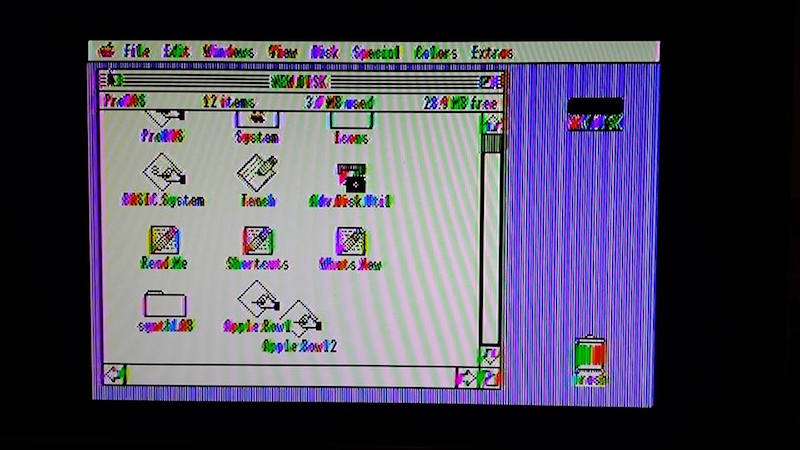
AV2HDMI GSOS desktop, color mode
Dell 2001FP Comparison Photos
2001FP color game

2001FP mixed mode text close-up
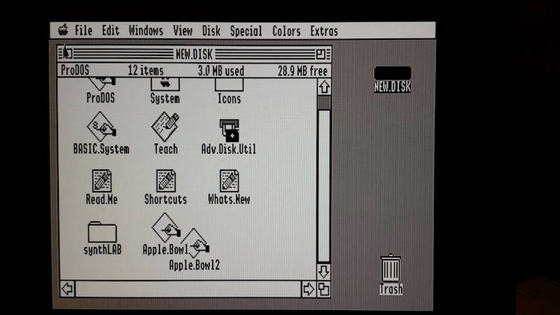
2001FP GSOS desktop, monochrome mode
2001FP GSOS desktop, color mode
For the money, I think the AV2HDMI is a good solution for semi-frequent use. The Dell 2001FP was slightly better overall, and a real composite CRT would surely have been better still (I don’t have one). There are also machine-specific VGA adapters available for some Apple II systems. But because I don’t boot my Apple II hardware very often, this was exactly what I needed to simplify my set-up.
Read 7 comments and join the conversationThe Amiga Years

I recently watched a new documentary about the Amiga years: From Bedrooms to Billions. It’s a $5 Vimeo rental that will be fascinating for anyone who lived through the 1980’s home computer revolution, or who’s interested in retro-computing technology. I was pleased to see a fair amount of technical content, as well as tons of interviews and more general discussion of the Amiga “scene” and the contemporary computer industry. There’s some nice discussion of other period computer systems too, especially the Atari ST series.
Amiga was a Silicon Valley start-up company, founded by Jay Miner and staffed by many ex-Atari engineers. They ran into financial difficulties during development, and were eventually bought by Commodore. The first Commodore Amiga 1000 computer was released in 1985, and its graphics, sound, and multitasking capabilities were far beyond any other home computer of the time, except perhaps for the Atari ST. As a high school student, I bought a second-hand Amiga 1000 system in 1989 and was absolutely stunned by its graphics fidelity. Yet I never really got into programming or hacking with the Amiga, and in my life it functioned only as a fancy game machine. I switched to a Macintosh when I went to university, and never looked back.
The Amiga Years reminds me of a few other nice documentaries about early computer history.
Get Lamp – A two-hour look into text adventure games, their roots in spelunking and Dungeons and Dragons, and especially Colossal Cave Adventure and Infocom. You are likely to be eaten by a grue.
BBS: The Documentary – Before the internet was common for home users, there were modems and bulletin board systems. This documentary does a great job of describing the BBS scene, as well as some of the technical backstory surrounding protocols and software that I’d never heard before.
What tech documentaries have you seen and enjoyed?
Read 2 comments and join the conversationIntroducing the Mac ROM-inator II
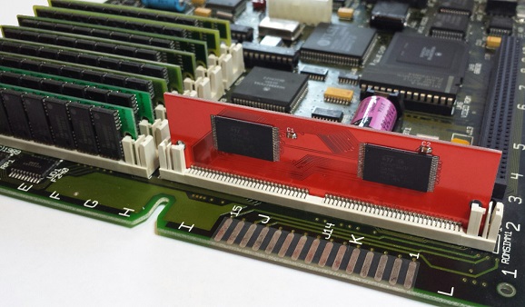
Say hello to a new retro-computing gizmo – the Mac ROM-inator II! It will supercharge your vintage Macintosh II series or SE/30 computer, by replacing the stock ROM with a programmable flash memory module. Add a bootable ROM disk, change the startup sound, hack the icons, gain HD20 support and a 32-bit clean ROM. Go nuts! The Mac ROM-inator II is available now in the BMOW Store.
The flash ROM comes pre-programmed with a custom ROM image with the following changes as defaults:
- Customized startup chime – major 9th arpeggio
- ROM disk image provides a diskless booting option
- New startup menu screen displays installed RAM, addressing mode, and ROM disk details
- Built-in HD20 disk support
- 32-bit clean
- Memory test is disabled for faster booting
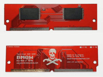
- Happy Mac icon is replaced by a color smiling “pirate” Mac
The ROM-inator II is derived from Doug Brown’s original Mac ROM SIMM design, used with permission. A portion of sales goes back to Doug.
ROM Hacking Magic
All the early Macintosh computers have some low-level functions stored in ROM. It’s the Mac equivalent of a PC’s BIOS. These ROM routines are responsible for initializing the computer when the power is first turned on, checking to see what hardware is installed, finding an attached disk with OS software on it, and booting that OS. Even after the OS has booted, the ROM routines still handle many low-level functions like interrupt handling, keyboard support, and floppy I/O, as well as some higher level functions like drawing windows and icons. If you can control the ROM, you can control virtually everything in the computer.
Nearly every member of the Macintosh II, Quadra, and LC families has a 64-pin ROM SIMM socket on the logic board. In some cases, the stock ROM is in this socket. In others, the stock ROM is soldered directly to the logic board, but it can be overridden by a ROM SIMM in the socket. All that’s necessary is to figure how to build a ROM SIMM that’s physically compatible, and then program it with appropriate software. A few years ago, the important details were reverse-engineered by Doug Brown and others at 68kmla.org in an epic forum thread that stretched to over 1000 posts.
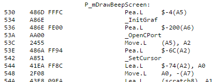
The ROM-inator II is a standard PCB, shaped and sized to fit the ROM SIMM socket. It comes pre-programmed with a base ROM image that’s modeled off the Mac IIsi ROM. This is a universal ROM that’s also capable of working in many other members of the Mac II family, including the SE/30, Mac IIx, IIcx, IIci, and IIfx. By patching key ROM functions, it’s possible to alter the Mac’s behavior in fundamental ways – a new startup chime, support for additional disk types, and a modified Happy Mac being a few examples. All it takes is a 68K disassembler and a lot of patience.
The stock ROM in most Macs of this period was around 512K in size, but the Mac’s address map devotes a full 8MB to ROM. In a normal Mac, the rest of this address space is unused. The ROM-inator II uses larger flash memory chips to take better advantage of the available address space. The first 512K of flash memory is used for the actual ROM code, and the rest is available for interesting goodies like a ROM disk image. Rob Braun’s original romdrv paved the way for ROM booting, and I’ve made several enhancements, including a startup menu and support for compressed disk images.
Compatibility
The pre-programmed ROM image is compatible with the Macintosh IIx, IIcx, IIci, IIfx, IIsi, and SE/30. The Mac ROM-inator II module is physically compatible with any Macintosh having a 64-pin ROM SIMM socket, except the Quadra 660AV and 880AV. This includes the previously mentioned models as well as many other Quadra, LC, and Performa models. For these other models, the flash memory will need to be reprogrammed with an appropriate ROM image.
For a similar ROM upgrade for the Macintosh Plus, 512Ke, 512K, and 128K, see the original Mac ROM-inator Kit.
HD20 Support and 32-Bit Clean ROM
A nice benefit of the pre-programmed ROM image is to add built-in support for HD20-type hard disks, such as the HD20 hard disk emulation mode of the BMOW Floppy Emu. The Macintosh IIx, IIcx, IIfx, and SE/30 lack HD20 support in their stock ROMs, so this replacement ROM enables those machines to use HD20 disks.
The pre-programmed ROM image also makes the Mac 32-bit clean, enabling it to use more than 8MB of RAM natively without the need for special system enablers or extensions. Some older Macintosh models like the IIx, IIcx, and SE/30 have stock ROMs that are “dirty”, meaning they can’t support 32-bit addressing without ROM patches. Using the Mac ROM-inator II and the pre-programmed ROM image, the Mac SE/30 can support up to 128MB of RAM!
ROM Disk
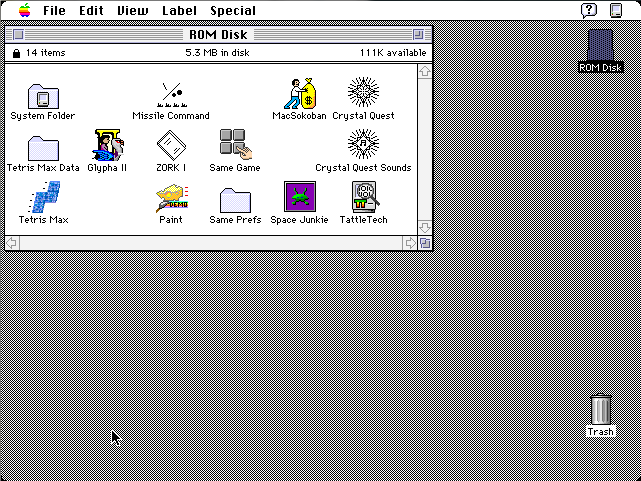
The built-in ROM disk is a 5.5MB bootable disk image containing System 7.1 and a collection of classic games. Using the ROM disk, it’s possible to create a diskless workstation without any physical disks attached. Once booted from the ROM disk, Appletalk file servers can also be mounted over a local network.
The ROM disk image is stored compressed in the module’s flash memory, and is decompressed on the fly as needed, in order to squeeze the largest possible disk image into the available space. This requires 1MB of RAM for caching of decompressed disk sectors, so a minimum of 2MB total system RAM is required. The ROM disk can be mounted as read-only, or as a read-write RAM disk.
Usage
When first powered on, the Macintosh will play a customized startup sound, and display diagnostic info about the amount of installed RAM, the current addressing mode, and the detected ROM disk type. After a moment, a startup menu will be displayed. To boot from the ROM disk as a read-only disk, press the R key on the keyboard. Or to convert the ROM disk into a writable RAM disk, press the A key. If no keys are pressed after five seconds, the Macintosh will boot normally from an attached SCSI disk, or wait for a floppy disk to be inserted.


Programming
The Mac ROM-inator II’s flash memory can be reprogrammed using an external SIMM programmer, providing the ultimate in customization. There’s 4MB of flash memory available for any purpose, like a custom ROM disk image, alternate ROM code, digitized sounds, user interface tweaks, or other crazy experiments. Using compression, this is enough for the base 512K ROM image plus a roughly 5.5MB uncompressed disk image. Or fill the whole space with a collection of different base ROMs, selected from a startup menu. Go crazy!
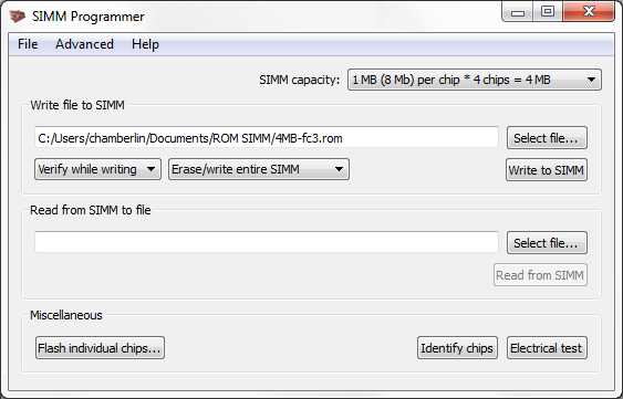
The SIMM programmer is currently a DIY project you can build yourself. See the schematics and PCB files, firmware, and host software on GitHub.
A second-generation SIMM programmer will be ready at the BMOW Store in summer 2016.
Happy ROM hacking!
Read 12 comments and join the conversation