

Apple Lisa Floppy Emulation

The Lisa computer was Apple’s precursor to the Macintosh, and it shared a lot of the same hardware and software. I’m going to look at adding Lisa support to my Floppy Emu disk emulator for Macintosh.
The Emu can already emulate a standard Sony 400K floppy drive, and the Lisa 2 aka Macintosh XL can use a standard Sony 400K floppy drive. (The relatively rare Lisa 1 used 5 1/4 inch Twiggy floppies.) So I *think* they should already be compatible at a low level, from an electrical and interface standpoint. That means the Lisa support could be added with just a firmware update, and no hardware changes necessary. My challenge is that I don’t actually own a Lisa! But with the assistance of a few kind Floppy Emu fans who are also Lisa owners, I’ve started getting closer.
The first obvious task is that the Emu firmware must be modified to support tag bytes. On both the Lisa and the Macintosh, a floppy sector’s data contains 12 bytes of tags, plus 512 bytes of normal data. On the Mac, the tags aren’t used for anything, and Floppy Emu just treats them as if they were always zero. Standard .dsk image files don’t even store the tag bytes, although Disk Copy 4.2 images do. But unlike the Mac, the Lisa needs those tag bytes in order for Lisa-formatted disk images to work correctly. So at a minimum, the firmware will need to fetch the tag bytes for each sector from the DC42 image file, instead of just pretending they’re zero.
Macintosh Emulation on the Lisa
But wait! Even without changing anything on the current Emu firmware, it should be possible to get it working on the Lisa under Macworks XL. Macworks is software for the Lisa 2 that basically turns the computer into an emulated Macintosh. After booting Macworks XL from a standard Lisa disk, you’ll then see the familiar Macintosh blinking question mark as it awaits a Mac boot disk. At that point, it should be possible to use a standard Floppy Emu and a Macintosh disk image to boot the Mac OS on the Lisa. Or boot into Mac OS with another disk, then use Floppy Emu to mount a second Macintosh disk. A helpful Lisa owner tried this exact experiment… and it didn’t work. The Lisa-as-Mac recognized that a disk was inserted, but complained that it wasn’t initialized, and offered to format it.
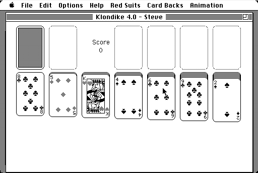
So why didn’t it work? I need to find the answer to that question before I even start worrying about tag bytes and other changes. My Lisa helper sent a few interesting screenshots, including the one above.
When booted using Macworks, the Mac OS on the Lisa includes a floppy control panel for something called the PFG, which I learned is the programmable frequency generator. Those control panel options look intriguing, but I’m not sure what they do. He tried normal and desperate modes with the same results.
From what little I could piece together, the PFG is an extra piece of hardware that not all Lisa 2’s have. If present, its purpose is to enable the Lisa to read floppies that were written in Macintosh II series computers that have three bit slip markers per sector. The bit slip marker is a special bit sequence on the floppy that helps the floppy controller get synchronized correctly. Apparently the Mac only needs 3 of them, although early Macs wrote 5 of them. The Lisa needs 5. With the Mac II series, the floppy logic was optimized to write only 3 bit slip markers, which made floppies written by those machines unreadable by the Lisa – hence the need for the PFG. I think.
The PFG shouldn’t be necessary when using a Floppy Emu, because the Emu sends at least 10 bit slip markers, and possibly as many as 55. So maybe there are too many, and that creates a problem? It shouldn’t be, given my knowledge of the Mac OS disk routines, if the Lisa is faithfully emulating a Mac.
Troubleshooting
To troubleshoot this, I need to find a way to get low-level floppy error data instead of just useless “this disk is not initialized” messages. Deep in the floppy routines, it knows if the read operation failed because it couldn’t adjust the drive speed properly, or couldn’t step to the desired track, or couldn’t find the sector on the track, or the sector checksum was wrong, or any of about 10 other possible failure reasons. There are a couple of ways I could do that:
1. I’ve already written a simple floppy testing program for the Mac. If I can get a Lisa with a hard drive and Macworks, I can copy the program onto the HD and run it from there. The trouble is, the generous soul who lives nearby and offered to lend me his Lisa doesn’t have an HD for it.
2. There’s a program called BLU (Basic Lisa Utility) that can be loaded from a floppy disk, and then used to run a variety of low-level tests, including floppy tests. The manual in appendix D shows the error info that’s provided, and it’s quite detailed. Unfortunately it’s sent to the serial port and not the screen, so I’d have to rig up a serial connection to another machine in order to see the output.
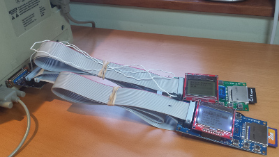
Without a hard disk, option 2 is really my only choice. But there’s another problem: I need a real floppy drive to load BLU from disk. But I need a Floppy Emu in order to test it. And the Lisa 2 only has a single floppy port. Hot swapping the drives is not an option. So I think what I’ll have to do is build a custom cable similar to my previous daisy chain adapter. This cable/adapter will allow the connection of two floppies drives to the same port, with both of them powered at the same time, and an external switch to control which one is enabled.
Other questions I’m unsure about:
- Does the Lisa have an IWM controller chip, like the Mac? I think it does. But possibly it’s clocked at a different speed.
- Is my understanding of the purpose of the PFG correct? Do all Lisas have one, or only some of them?
Assuming I can ever get this sorted under Macworks, then there are many other questions I’ll need to answer about tag bytes, the Lisa filesystem, and probably the DART disk image format. But getting Mac disks to work on the Lisa under Macworks is the first step.
Read 7 comments and join the conversationThe Sonic Bow Tie
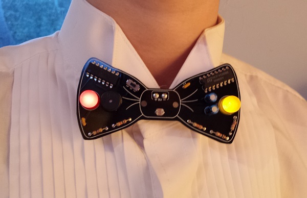
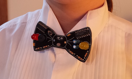
The Sonic Bow Tie is an electronic kit for engineering geeks with a sense of humor, available now at the BMOW store. The circuit board is shaped and sized like a real bow tie, and is colored classic black. Once assembled, a piece of ribbon can be anchored through the board’s central mounting holes, making it easy to wear at the collar of a dress shirt or tied around a ponytail.
Wearable computing is the latest trend, and you’re at a party listening to some hipster brag about his new iWatch. “Hmm, not bad…” you say. Then you casually reach for your collar and switch on your SONIC BOW TIE 3000. Wham! Your audience is blown away by your neck-based audio-visual spectacle. Lights flash and a digital melody bursts forth. With a wave of your hand you exert theremin-like controls, shifting the pitch of digital warbling at will. The onlookers cry out “WHAT IS THIS SORCERY?!”
Attending a wedding soon? Graduation ceremony? Audience with the pope? The Sonic Bow Tie 3000 is the perfect geek accessory for any formal occasion.
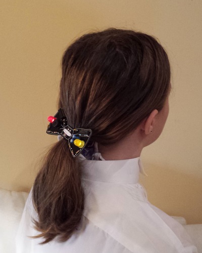
Ladies: are bow ties not your style? Turn it around, and make a dazzling electronic ponytail holder perfect for your next Maker Faire presentation or inaugural ball.
While a pair of jumbo 10 mm LEDs flash, the bow tie repeats a simple 8-note digital melody, alternately soothing and annoying those around you. A center mounted photo-resistor acts as a light sensor, biasing the melody’s pitch. Turn your body towards the light, and the pitch shifts upward. Turn away or shade the sensor with your hand, and the pitch shifts downward. Fortunately there’s also an on/off switch, for when your friends threaten you with bodily harm if they hear one more second of that #*&($#@!
The kit contents are simple through-hole parts, so it’s easy to solder even for a beginner. Build one for yourself, or get a kit for your kid/student/friend and assemble it together. Who wants the boring LED blinker in a typical learn-to-solder kit, when you could have a crazy bleeping sonic bow tie theremin?
How it Works
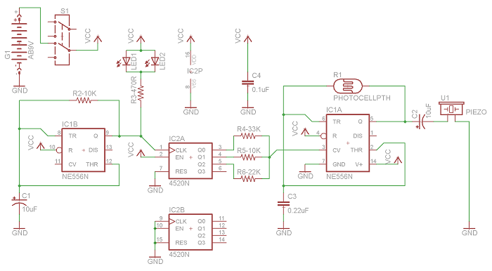
The fun begins with a classic 555 timer, configured in astable mode to generate a square wave with a frequency around 1000 Hz. This is IC1A as shown in the circuit diagram. The exact frequency of the square wave is determined by the values of C3 and R1. R1 is a photo-resistor whose resistance varies with illumination. This causes the timer frequency to shift up or down in response to changing light conditions. When connected to a speaker, it creates a continuous tone whose pitch changes depending on the light.
A continuous tone isn’t very interesting, but we’re not done yet. A second 555 timer is also configured in astable mode, generating a square wave at about 4 Hz (250 millisecond period). This is IC1B in the circuit diagram. A pair of LEDs are connected to this square wave output, causing them to blink 4 times per second.
The 4 Hz signal is also used as the clock input to IC2A, a 4-bit binary counter. The circuit uses a CMOS CD4520 binary counter chip, instead of a more common 7400 series binary counter, because the CD4520 can tolerate supply voltages up to 20 V. This makes it possible to run the entire circuit directly off a 9 V battery, with no voltage regulator.
The lowest three bits of the current count are connected through series and parallel resistors to the control voltage input of the first 555 timer. This biases the continuous tone up or down in pitch, with a new bias voltage appearing every 250 milliseconds when the counter advances. The result is a repeating melody of eight notes, whose relative pitches are set by the binary counter, and whose overall pitch can be shifted further up or down by changing illumination at the photo-resistor.
Wear and Usage
To wear the Sonic Bow Tie 3000 around your neck, drop the battery inside your front shirt collar and allow it to hang loose by the clip wires. Normally this is all that’s needed to anchor the bow tie at your collar. If desired, a ribbon or shoelace can be passed through the two holes in the center of the circuit board, and tied around your neck.
To wear the bow tie as a ponytail holder, pass a ribbon through the center holes, and tie it around your hair at the base of your skull. The battery can be dropped inside the rear of your shirt collar, or hidden inside your hair.
The pitch bends of the digital melody are controlled by the level of illumination on a photo-sensor mounted at the tie’s “knot”. The bow tie works best indoors, in a room with moderate lighting. To shift the melody’s pitch higher, move closer to a light source, or turn the bow tie to face directly towards the light. To shift the melody’s pitch lower, move away from the light source, or shade the photo-sensor with your hand. By waving your hand rapidly above the photo-sensor, a warbling vibrato effect can be achieved. Is it science, or sorcery?
Read 1 comment and join the conversation2 GB Disk Images with Floppy Emu
A few months ago I added a hard disk feature to Floppy Emu: HD20-compatible disk emulation, with disk images up to 2 GB! Unfortunately many people didn’t see the news, and I continue hearing from folks who are unaware their Emu can do anything more than 800K or 1440K floppy images. If you’ve got a Floppy Emu board and a Mac 128K, 512K, 512Ke, Plus, SE, Classic, Classic II, Portable, IIci, IIsi, or LC: your machine supports HD20-compatible disks! Install the latest HD20 alternate firmware now, and start working with giant disk images large enough to hold your entire vintage software collection. You can download the alternate firmware from the Floppy Emu product page.
The HD20 alternate firmware also supports switching back to floppy emulation mode, for those times when you need it. Press the SELECT button while the Emu is displaying its version info on the LCD, and it will show a menu for choosing between hard disk and floppy emulation modes.
Happy hacking!
Be the first to comment!ROM-inator Disk Setup Tutorial
The Mac ROM-inator kit adds 1 MB of rewritable flash memory to your vintage compact Macintosh. A bootable ROM disk is one of many interesting possibilities this creates. The kit comes with a preprogrammed System 6.0.8 boot disk image, but how can you edit the disk image or replace it with a different one? My previous description skipped over some steps that may not have been clear to everyone, so read on for a detailed tutorial on creating and transferring the disk image.
Creating the Disk Image
The first step is to download or create a new disk image file, to be used for the ROM disk. These files normally end with a .dsk filename extension, and are commonly used with Macintosh emulation tools and disk copy programs. The Floppy Emu disk emulator also uses .dsk files, so if you’ve already got an Emu, you can probably use one of your existing disk image files as a ROM disk. You can also download .dsk files for many old system versions, utilities, and games at tkc8800.com. As long as the file isn’t larger than 864K, and contains bootable system software, it should work.
But using an existing disk image is boring. What if you want to create a custom disk image, with your own personal collection of games? There are many ways to do it, including the tools HFVExplorer (Windows) or Fuse HFS (OS X). The method I’ll describe here uses a popular software-based Macintosh emulator called Mini vMac. We’ll use this software to set up a new .dsk file, and fill it with goodies.
- Download Mini vMac here. It supports OS X, Windows, Linux.
- Before you can run Mini vMac, you’ll need a Macintosh ROM file (vMac.ROM) and system disk. You can find both in this tutorial file archive.
- Move
vMac.ROMinto the same folder as the Mini vMac application you just downloaded, and follow the setup instructions. When the instructions ask you to drag your bootable disk image, use the fileHD20.dskfrom the previous step’s file archive.
You’re now running an emulated Mac Plus! You can attach additional disks by simply dragging the .dsk files into the Mini vMac window. Unlike a real Plus, you can have many disks attached all at the same time. Let’s create a bootable disk image for use with the ROM-inator, containing a few classic Mac games.
- The archive contains an empty 864K disk image file called
rominator-disk.dsk. Drag this file into the Mini vMac window. - Download
.dskfiles for Klondike, Brickles, MacMan. Drag these into the Mini vMac window too.
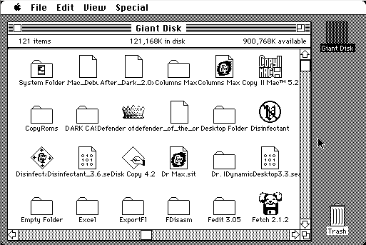
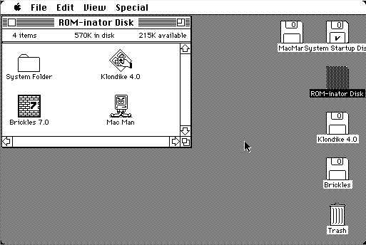
You should now have five different disks mounted in Mini vMac:
- In Mini vMac, drag the System Folder from the System Startup Disk to ROM-inator Disk. This copies the system software, and makes ROM-inator Disk a bootable disk.
- Copy the games from the other disks onto the ROM-inator Disk. Some of the game disks also contain System Folders. Don’t copy these – only copy the games themselves.
You should now have a finished ROM-inator Disk:
Drag the ROM-inator Disk icon to the trash can to unmount it. Your finished ROM disk image is now stored in the file rominator-disk.dsk.
Transferring the Disk Image
Now that you have a disk image file, how do you get it onto your Macintosh so you can write it to the ROM-inator? Once again there are several ways to do it, including connecting your compact Mac over Localtalk to a slightly less ancient Mac that also has Ethernet, or using an external SCSI drive to sneakernet the file from another computer. But the simplest method is to use a Floppy Emu configured as a hard disk emulator in HD20 mode.
Normally you would copy a .dsk file to the Floppy Emu’s SD card, so you could use it on the Macintosh as if it were a real disk. But in this case, we actually want the .dsk file itself transferred to the Mac, which means we need to put the file rominator-disk.dsk inside another disk image. We’ll use Mini vMac again.
- Start Mini vMac.
- When you see the blinking question mark, drag
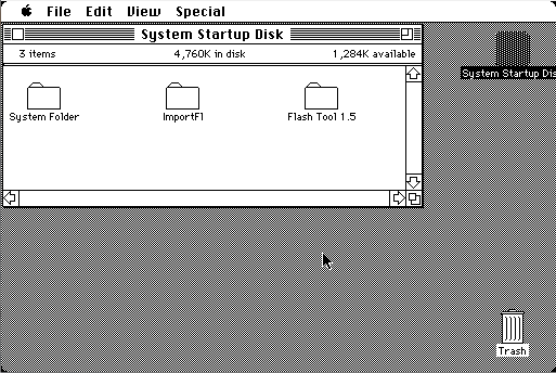
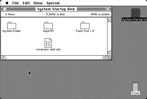
HD20.dskinto the Mini vMac window. - In Mini vMac, on the System Startup Disk, you’ll find a program called ImportFl. Double-click the icon to run it.
ImportFl will now wait for a file to import from the host operating system:
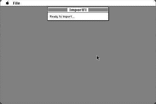
- From your OS X, Windows, or Linux desktop, drag the file
rominator-disk.dskinto the Mini vMac window. - When prompted, choose a destination on System Startup Disk to save the file. Any location is fine – just remember where you put it, so you can find it later.
- Quit ImportFl.
rominator-disk.dsk is now stored as a data file, inside HD20.dsk.
- Exit Mini vMac.
- Copy
HD20.dskto Floppy Emu’s SD card. - If you haven’t already, update your Floppy Emu with the latest HD20-aware firmware. You can download the firmware from the Floppy Emu product page.
- Connect the Emu to your Mac, and turn it on. If necessary, press SELECT while the Emu is displaying version info on the LCD, in order to switch into hard disk emulation mode.
- Reset the Mac. It will boot from the
HD20.dskimage on the SD card.
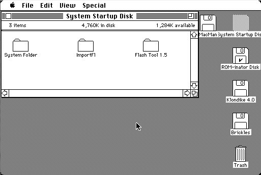
rominator-disk.dsk is now visible as a regular file, on the System Startup Disk mounted by your Mac.
Writing the Disk Image
The final step is the easiest – writing the new disk image to the ROM-inator. The utility program Flash Tool makes this easy, and to make it even easier, Flash Tool is already included in the HD20.dsk image.
- On your Mac, on the System Startup Disk, you’ll find a program called Flash Tool. Double-click the icon to run it.
- Under the heading “ROM Area to Update”, select ROM Disk Image.
- Press the Select File… button, and browse to the location where you previously stored
rominator-disk.dsk. Select this file.
The Flash Tool setup should now look like this:
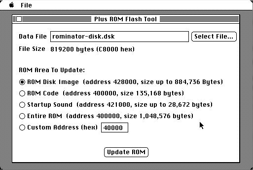
- Press the Update ROM button. You’ll see a progress bar while it’s working. The update takes about 60 seconds.
- When the update is finished, reset your Mac.
You’re done! It looks like a lot of steps, but the whole process only takes a few minutes. Your new disk image is now stored in flash memory by the ROM-inator. Whenever you turn on your Mac, you’ll see the “press and hold R now” message. To boot from the ROM disk, press and hold the R key on the keyboard for a few seconds. If R is not pressed, the Macintosh will boot normally from an attached SCSI disk, or wait for a floppy disk to be inserted.
Have fun!
DB-19 Madness
I have the DB-19 connectors. They’re mine, all mine! MINE!! MWAAAHAHAHAHA!!!!!
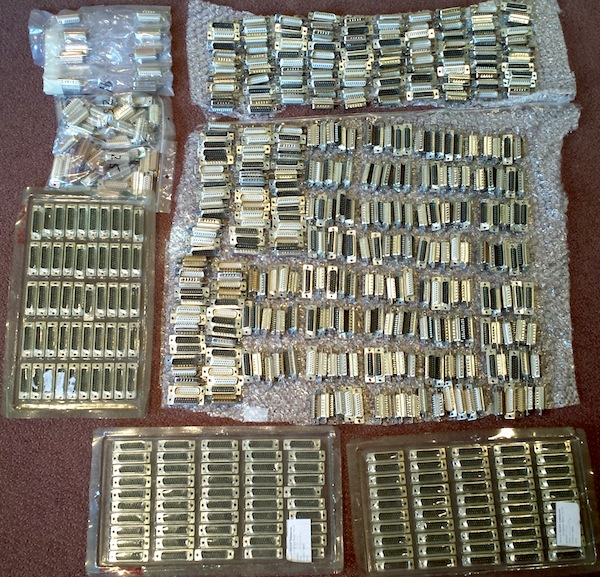
*Cough* Sorry about that, I don’t know came over me. So the great DB-19 panic of 2015 has ended, and I’ve got 581 of these metal and plastic beauties. Of course there will probably be another DB-19 panic in 2016 when these ones run out, but hopefully I’ll have worked out another solution before then.
If you’re new to this discussion and wondering what a DB-19 is, it’s a D-SUB connector like the more familiar DB-9 serial or DB-25 parallel connectors used on many older computers. My main product is a disk emulator for 1980’s Macintosh computers, and those computers were built with a DB-19 floppy port, so my emulator board must have a DB-19 connector. The trouble is that nobody has manufactured DB-19 connectors since about 1990, as far as I can tell. Since then the small remaining demand has been slowly draining the surplus warehouses that still have DB-19’s. Last month, the supply at the few big warehouses that still had them all went to zero, and it became virtually impossible to buy them anywhere.
This touched off a crazed panic on my part, and I went digging under every rock from San Jose to Skopje to Kuala Lumpur to find these things. And when I found some, I bought them ALL. I even got a friend of a friend to hand carry some connectors from Malaysia to California for me! After two weeks of furious hunting, the hoard above is my result. I can say with pretty good confidence that this is the largest remaining stockpile of DB-19s in the world. If anybody has more, they’ve certainly made them so difficult to find and buy that they may as well not exist.
So what happens in 2016 when the supply runs out? Plan A is to find a D-SUB manufacturer with some old DB-19 molds who is willing to make more, or who can adapt their existing DB-25 process to make DB-19s too. I’ve received several quotes from D-SUB manufacturers, but unfortunately I probably can’t afford the setup costs to do this. I’ve contacted a few people in the Atari and Apple II worlds who also use DB-19 connectors, and if we pool our efforts and share the cost, it might work. I’m continuing to talk with D-SUB manufacturers in the hopes that we can find a solution that works for them and for me.
Plan B is to make a DB-19 substitute from a custom PCB and header pins. It wouldn’t really be a DB-19, but it would fit a DB-19 female socket, and could be manufactured fairly easily.
Plan C is the brute force solution: get a huge pile of DB-25 connectors, and cut each one with a band saw. 🙂
Footnote: Many people have written to me about DB-19 connectors they saw advertised for sale on the web. Thank you! Unfortunately, it’s very likely that the store does not actually have any DB-19 parts, and never will. It seems to be common practice for parts warehouses to list parts they don’t actually have available, and even for the web page to claim they’re in stock. Unless you hear directly from somebody at the store who can confirm they really do have DB-19 connectors, and how many they have, it’s probably just a phantom.
I’ve also found that many of the web-based parts warehouses are just alternate electronic storefronts for other warehouses, or aggregators for several other warehouses, but don’t actually have any inventory of their own. This makes it look like there are more people selling DB-19 connectors than there really are. Instead, it’s just different salesmen all selling the same stock.
Read 16 comments and join the conversationMacintosh Disk Daisy Chaining
Floppy Emu was originally developed to be purely a floppy disk emulator for the Macintosh. More recently, I added the ability to emulate a hard disk too, for those Mac models that support Apple’s original HD20 hard drive. This enabled the use of much larger disk images up to 2 GB, but it also enabled another feature that’s been unexplored until now: daisy chaining!
With a standard Macintosh floppy drive, there can only be one drive per floppy port. There’s only a single ENABLE signal at each port, and the Mac ROM only expects to find one drive on each port. So you can have one drive on the external floppy port (if the Mac has one), and one drive on the internal floppy port, and that’s all. If you somehow brewed up a custom splitter cable to connect two floppy drives to a single floppy port, it definitely wouldn’t work, and would cause electrical contention that might damage the drives or the Mac. This would be true whether you used Floppy Emus, or real floppy drives.
When Apple introduced the HD20 external hard drive in 1985, the situation changed. An often-overlooked feature of the HD20 is the floppy-out connector on the back of the drive. Combined with new HD20-aware code in the Macintosh ROM, this made it possible to daisy chain multiple drives together for the first time. Floppy drives were still “dumb” and didn’t understand daisy chaining, but you could build a chain of one or more HD20 drives, with an optional floppy drive at the end of the chain. Aha!
Signaling
To support daisy chaining multiple drives on a single port with a single ENABLE signal, Apple used a trick. The ENABLE signal from the Mac’s floppy port was connected to the first drive in the chain. That drive used internal logic to generate a new ENABLE signal, which it passed to the second drive in the chain. The second drive did the same for the third, and so on. As long as things worked correctly, only one drive at a time would ever see ENABLE asserted, so the drives could coexist happily on a shared port.
To select the next drive in the chain, the Mac asserted and then deasserted another signal called LSTRB, while keeping ENABLE asserted the whole time. The drive that believed it was currently enabled was supposed to see this, disable itself, and enable the next drive. When ENABLE was finally deasserted, all drives would disable themselves. When ENABLE was later asserted again, the first drive in the chain became enabled, and the process began anew.
This daisy chaining technique was mentioned in a dusty old HD20 document I found, but I was never able to get it to work as described in the document. Only after a lot of trial and error, and reverse engineering of the HD20 code in the Macintosh ROM, was I finally able to get daisy chaining working with the Floppy Emu.
Why?
Is daisy chaining actually useful for computer collectors in 2015, or just a novelty? I can see two scenarios where it would be helpful:
With a Mac 128K or 512K, to use one Emu as a floppy source for loading Apple’s HD20 Init, and a second Emu in HD20 mode as a boot volume. Since the Mac 128K and 512K don’t have built-in ROM support for HD20, they normally can’t boot directly from an HD20 without a real floppy disk with the HD20 Init on it.- With any Mac, to use one Emu in HD20 mode as a primary boot disk, and a second Emu in any mode as a tool for transferring files between Macs or between a PC and a Mac.
The Daisy Chain Board
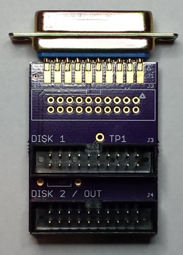
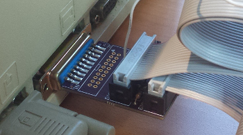
To make daisy chaining easy, I designed the daisy chain adapter board pictured above. Plug the adapter into your Mac, either directly at the external floppy port, or with a cable to the internal floppy port. Then connect two drives to the DISK 1 and DISK 2 connections, and an extra wire to disk 1’s TP1 output, and you’ll be in daisy chaining heaven. Or link a second adapter board at DISK 2 to create an even longer daisy chain. Although it looks like a Y-splitter, topologically the enable signals form a daisy chain.
I was unsure how popular daisy chaining might be, so I only had a few samples of this board made. If you might be interested in buying a daisy chain adapter board, please let me know. If there’s sufficient interest, I’ll build more.
Maybe Don’t Try This At Home
Building your own daisy chaining setup requires some non-standard connections and custom wiring between two or more Emu boards. Damage to the Emus or the Mac is definitely possible if you botch this, so be extra careful to check your connections, and don’t proceed if you’re uncertain about your ability to do it correctly.
Briefly, all the drives should be connected as a shared bus, with the same floppy cable signals going to each one, except for the ENABLE signal. The ENABLE signal from the Mac should be connected to the ENABLE input of the first drive. The TP1 test point of the first drive should then be connected to the ENABLE input of the second drive. TP1 of the second drive should connect to the ENABLE input of the third drive, and so on.
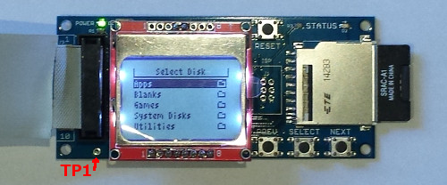
You’ll find TP1 on your Floppy Emu board near the bottom left corner of the LCD’s overhang. It’s an unlabeled metal-ringed hole just below the 10×2 black plastic IDC connector.
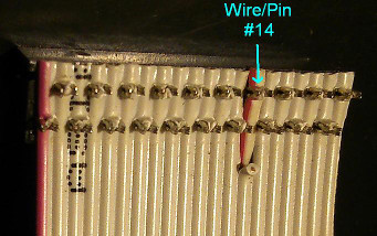
If you’re building a custom cable using standard IDC-20 flat ribbon cable, ENABLE is on pin 14. Pin 1 on the cable is colored red, so start at the red end and count 14 wires to locate ENABLE. Count twice, cut once!
Important Notes
- Be sure you’re using the latest HD20-aware firmware for the Emu, which as of this moment is HD20-0.7A-F14.5. You can download the firmware here.
- The first Emu in the chain must be in HD20 hard disk emulation mode (or a real HD20 if you’ve got one). You can string together more HD20 mode Emus if you’d like. The chain can end with zero or one Emus in floppy mode, or a real floppy drive. If there is a floppy-mode Emu, it must be at the end of the chain.
- In order for daisy chaining to work, your Mac must have HD20 support in ROM, or boot from a disk that contains Apple’s HD20 Init. The supported machines are the Mac 128K and 512K (with HD20 Init), 512Ke, Plus, SE, Classic, Classic II, Portable, IIci, IIsi, and LC (but not LC-II or LC-III).
- The topology and total length of the daisy chain cables is important. Longer cables with forking paths will cause signal reflections and delays that may cause the Emus to work intermittently when daisy chained, or not at all.