

Hacking the Happy Mac
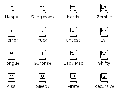
Anyone who used a Macintosh in the 80’s or 90’s remembers the Happy Mac icon – the smiling computer face that appeared on the screen while the machine was booting up. With my new ROM-inator flash memory kit for vintage compact Macs, hacking the Happy Mac icon is easy. The happy face is stored as a 20 byte raw bitmap, beginning at offset $FD2 (hex) in the ROM code file. It’s a 16 x 10 rectangle within the “screen” area of the surrounding Macintosh icon.
All of the icons above can be downloaded from the ROM-inator page. I went with the sunglasses for my Mac Plus, ’cause that’s how I roll…
Read 1 comment and join the conversationIntroducing the Mac ROM-inator
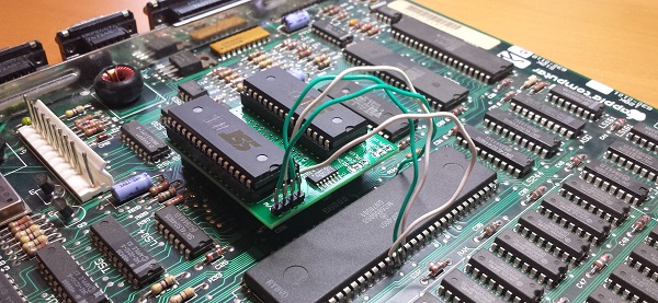
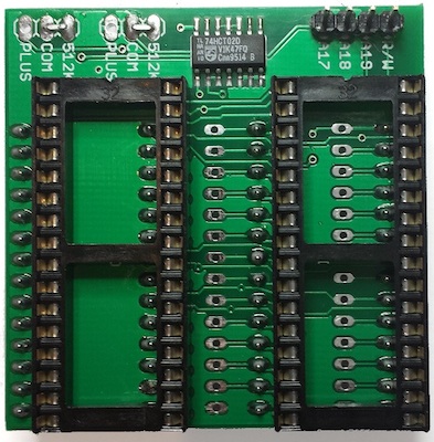
Today I’m excited to introduce a new product: the Mac ROM-inator kit. The ROM-inator replaces the stock 64K or 128K of ROM in a compact Macintosh with a full 1 MB of flash memory, unlocking wild new possibilities. Add and edit a bootable ROM disk! Replace the startup sound, or tweak the ROM code behavior. What’s best is the flash ROM’s contents can be updated from within the running Macintosh, allowing for crazy customization experiments. For power users, binary editing of the ROM image opens new possibilities like changing the Happy Mac icon, altering the built-in fonts, and modifying the system startup routines.
The Mac ROM-inator supports the Macintosh Plus, Mac 512Ke, 512K, and 128K. The kit includes two preprogrammed flash memory chips, with a System 6 ROM disk and a “mooo” startup sound. It’s priced at $25, and is available immediately. Get yours now!
The ROM-inator is a descendant of Rob Braun’s original Mac Plus ROM Adapter and disk driver. More details about its inspiration and development are here.
Usage
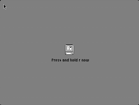
When first powered on, the Macintosh will play a customized startup sound, and display a “pirate Macintosh” icon. To boot from the ROM disk, press and hold the R key on the keyboard for a few seconds. If R is not pressed, the Macintosh will boot normally from an attached SCSI disk, or wait for a floppy disk to be inserted.
The 1 MB flash ROM includes 132K for ROM code, 28K for a custom startup sound, and up to 864K for a ROM disk image. The preprogrammed flash chips contain ROM code based upon the Mac Plus ROM. If used with a Macintosh 128K or 512K, it will turn them into a 128Ke or 512Ke. This will also give those machines native HD20 support, for use with Floppy Emu in HD20 hard disk emulation mode.
The utility program Flash Tool can update the flash ROM from within the running Mac. Alternatively, the flash chips can be removed from their sockets and reprogrammed using a standard EPROM programmer.
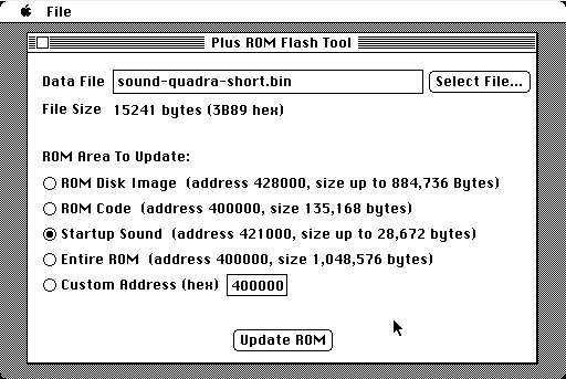
To use Flash Tool, simply select the ROM area and the data file to use for the update. The program will verify that the data file is the correct size for the area to be updated. After about sixty seconds, it’s done!
Read 5 comments and join the conversationA Good Idea That Wasn’t
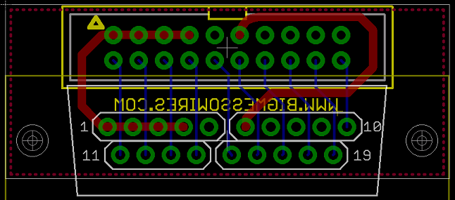
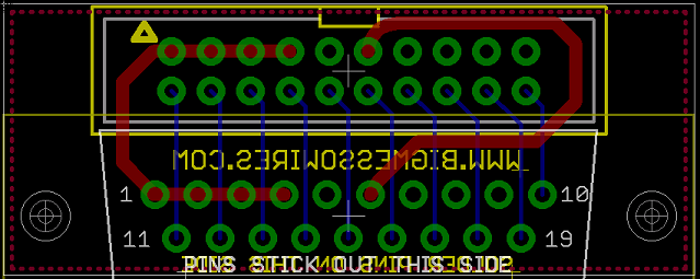
A few weeks ago I designed a right angle adapter PCB for the Floppy Emu. The idea was to make a little board that plugged into a standard Emu and converted it to right angle rear mounting, with the LCD and buttons facing outward, and the main board leaning against the back of the computer’s case. It’s possible to hack your Emu to do this, but I wanted a solution without needing to resolder or modify anything.
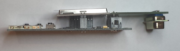
Unfortunately the geometry is wrong, and the adapter doesn’t fit. In order to plug into the computer’s floppy port, the DB-19 connector on the adapter board needs to extend about 1 cm behind the main Emu board. But as you can see in the photo, it doesn’t extend behind the main board at all. It’s not even close. So the main board just whacks into the Mac’s case and won’t let the adapter go any further.
I knew the geometry would be a problem even before I sent the adapter boards off to be made. I was hoping there would be enough flex or play in the connections that it would still fit, but no dice. Chalk this one up as a learning exercise!

Bagging the DB-19
After days of fruitless searching, I finally found a shop in Macedonia with a stock of DB-19 male solder cup connectors. I bought them all! To be honest, I had to check a map to learn where Macedonia is, because it’s not exactly one of the top 10 most likely sources for electronic components. Total cost for 500 pieces including VAT and shipping was 27019 denar, or about $497 US dollars at current exchange rates, so that’s just under $1 per connector. Not bad, considering most other places wanted to charge $2 to $4 per connector, if they even had them in stock.
I may have to pay import duty tax. I’m not sure how that works, but I assume DHL or somebody will tell me what’s needed. The total price also includes about $50 in European VAT, which as a United States buyer I shouldn’t need to pay. Anyone have experience in getting VAT refunded? I presume there’s a form I need to send somewhere.
At almost the same time that I heard from Macedonia, I also got my first concrete response from a supplier in China about manufacturing new DB-19 connectors. We discussed two options: a soft tooling setup, with a lower initial setup fee but higher per-piece cost, or a hard tooling setup with the opposite cost balance. I asked for soft tooling. After many rounds of back and forth, I finally received a setup cost quote of (drum roll…) $11,185. They didn’t state what the per-piece cost would be after setup, but already it’s too expensive. Unless I could somehow band together with other DB-19 users in the Atari and Apple II communities for a large combined order of 10000+ pieces, it’s not practical.
I won’t rest easy until the package from Macedonia arrives. Even though they say they’re sending 500 pieces of DB-19P male solder cup connectors, and the photo on their web site looks right, I’ve found too many vendors whose web sites are out of date, or whose stock mysteriously disappears when you try to place an order. Or maybe they’ve got 500 DB-25 connectors in a mislabeled box, and will be sending those to me. I’m crossing my fingers in hopes that nothing will go wrong.
Floppy Emu demand has been widely variable, so I’m not sure if 500 pieces will be enough supply to last two years or only a few months. The Macedonian shop wasn’t sure if they could get more stock, so at some point I’ll likely run out of DB-19 connectors again. I’ll continue hunting for other sources and refining my DB-19 substitute designs.

Edit: I was just about to post this update, when I noticed the order confirmation page from the Macedonian shop says the order both was and wasn’t successful. So which is it? Ugh. The saga continues…
Read 7 comments and join the conversationDesigning a DB-19 Substitute
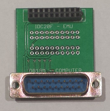
I’m still searching for a source of more DB-19 connectors, but so far I’ve been unsuccessful finding a single one. As a backup plan, I’m exploring building a DB-19 substitute using a PCB and 19 individual pins. The result won’t really be a proper D-SUB connector, because it won’t have a surrounding shield, but it will still fit a DB-19 female port. Add a standard IDC-20 connector to the back side of the same PCB, and it can make a strange but effective DB-19 to IDC-20 converter cable.
The first version of this PCB is shown above, and is based on an idea by Charles Phillips. It uses four sections of standard 0.1 inch (2.54 mm) pitch male header. That’s the wrong pitch – a D-SUB connector has a 2.77 mm pitch – but it’s close enough that short sections of 4 or 5 header pins can bend a little and still fit the D-SUB. The advantage of this version is that it’s cheap and easy to make, and should be no trouble for the board assembly shop. Reliability is a question, though. Slightly bent pins may not make good contact inside the female port, or there may be an issue with square header pins in round port holes. But the initial tests look promising.
The second version of the PCB is very similar to the first, except the pads are all on a 2.77 mm pitch D-SUB grid instead of a 0.1 inch (2.54 mm) pitch. And instead of using 0.1 inch male header, it uses 19 individual D-SUB crimp pins in a non-standard way: the pins are each soldered in place, and then the crimp sections are cut off. The advantage of this version is that the pin spacing is perfect, and the pins are round, so the fit in the female port should be perfect. But it would be a couple of dollars more expensive, and it’s something that would have to be done manually, without standard assembly tools or processes. I need to check with the board assembly shop I’m using to see what effect it would have.
Neither of these PCBs has a shield surrounding the 19 pins, so if somebody tried hard enough, they could insert the connector aligned incorrectly. With the whole unit offset by 1 pin horizontally or vertically, the connected electronics might get zapped with 12 volts on a signal pin. You’d have to try pretty hard to do this, though.
Read 7 comments and join the conversationFloppy Emu – Back in Stock
After a long delay, Floppy Emu is back in stock and available for sale now. It’s available with a built-in connector for placement at the rear of the Mac, or bundled with a three foot extension cable so you can place it anywhere on your desk. Beginning with this batch of hardware, the LCD backlight is now enabled by default too. Woot!
I’m having difficulty locating sources for the floppy connector, a DB-19 male D-SUB. These were common in the 80’s and 90’s, but the supply has dried up and they’re almost impossible to obtain now. I’m still chasing down possible sources and investigating alternatives. If I don’t find a good solution, this may be the last batch of Floppy Emu hardware for a while.
As a new option, I’m now offering an SD card preloaded with disk images of System software versions 1 through 7.5.3, as well as some classic software like MacPaint, Hypercard, After Dark, Kid Pix, and Fool’s Errand. Cases for the Floppy Emu are also available, in brown wood hardboard or clear acrylic.
For those who have waited patiently on the waiting list since mid-December, thank you. Happy emulation!
Be the first to comment!