

Supply Chain Snafu
Where and how do you find the parts needed to build your hardware? Selling Floppy Emu on a small scale has introduced me to the difficulties of managing a supply chain, and I’ve discovered it’s more difficult than it looks. Doing it wrong means higher costs, more risk, and a danger of running out of key parts at the wrong time. Due to my own poor planning, Floppy Emu has been stuck at “out of stock” for far too long, and I can’t even say for certain when it will be back.
Choosing a vendor from whom to buy parts seems like it should be easy: just use a search engine like Octopart to find the vendor with the lowest price. Sadly it’s not that simple. Some guy on eBay may have the lowest price, but how can I know if his parts are good quality, or if they’re recycled, relabeled, or even counterfeit? Is the savings enough to be worth the risk? And then there are “overstock” vendors like Arrow, Avnet, and Verical, who often have very good prices but require minimum orders of 100+ parts. Are they worth it?
Even if it’s clear which vendor is best for a specific part, it becomes less clear when all the parts are considered together. Floppy Emu is built from about 15 different types of parts, and if I ordered each one from a different vendor, the combined shipping costs from all those vendors would kill me. It’s a balancing act, and it’s often necessary to buy a part from a vendor whose price isn’t the best, so I can combine it with other parts in the same order from that vendor.
Mapping all this out is a pain, but at least it only needs to be done once, right? Wrong. The vendor prices are constantly changing, and less commonly the minimum order sizes change as well. So every time I go to order more parts, I have to start the analysis over again.
I struggle the most with determining how many parts to order. Virtually every vendor has a sliding price scale, where the per-part cost decreases as the number of parts ordered goes up. So there’s an incentive to make orders for large numbers of parts to drive down the average cost, but there’s also a risk. If I order 100 ATMEGA1284 microcontrollers, and then interest in Floppy Emu dries up, I could be left with $1000 worth of useless chips sitting on a shelf. But if I order them 10 at a time, I’ll not only be paying more per chip, I’ll also be reordering nearly every week and risking running out of parts if demand temporarily spikes up.
Out of Stock
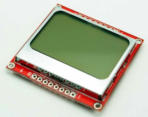
My current problems are due to Floppy Emu’s LCD display. In mid-January I thought I had two boxes of LCDs remaining, when in reality I only had one. When I discovered the truth, I only had about six LCDs left. I placed an order for more LCDs on January 29, from the same Chinese vendor I’d used in the past. But then Chinese New Year hit, and nothing happened for a week. The package finally shipped on February 6. Meanwhile, I ran out of LCDs on February 8 and put Floppy Emu into “out of stock” status.
My last order from this vendor took 10 days to arrive from China, so I expected the new LCDs to appear around February 16. But that day passed with nothing in my mailbox, nor the next, nor the next. Time ticked by. As I waited, I accumulated enough Floppy Emu back orders so that the new supply of LCDs would already be nearly exhausted by the time it arrived, so I placed a second order for even more LCDs.
When I checked back on the first order, I saw the vendor was now quoting 25 to 30 working days for delivery. What?! That’s like a month and a half! I’m not sure if this was a change in policy, or the 10-day delivery time I had earlier was just an outlier, but they were now giving me an estimated delivery date of March 7-15. Somehow the second LCD order was estimated to arrive earlier, on February 28 to March 6, despite being ordered three weeks after the first LCDs and being shipped by the same method. And there’s no tracking info on either shipment, so there’s nothing to do but wait.
Read 8 comments and join the conversation
BMOW on RetroMacCast Show

Burning through my 15 minutes of fame, I was the featured guest on this week’s episode of the RetroMacCast show – listen to it here. RetroMacCast is a weekly podcast about vintage Macintosh systems, software, and collectibles. Hosts James and John have been doing this since (at least) 2008! They were kind enough to invite me to this week’s show, where we discussed Floppy Emu, Plus Too, Tetris Max, and my other Apple-related hacks.
This recording prompted an interesting side-discussion: have I been mispronouncing “Floppy Emu” for the past two years? Is it “emyoo” (short e + myoo, as in ’emulator’), “eemyoo” (long e + myoo, a flightless Australian bird), or “eemoo” (long e + moo, an electronic cow sound)?
Read 6 comments and join the conversationEmulating the Apple HD20
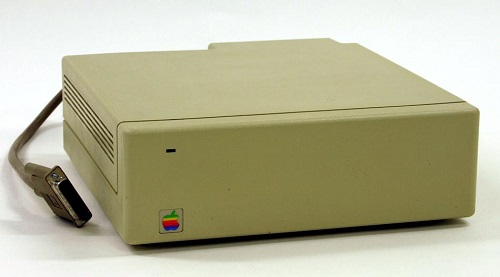
The Apple Hard Disk 20 (HD20) was an external 20 MB hard drive for the Macintosh, introduced in 1985. This was during the earliest days of the Mac’s history, before the introduction of SCSI support, so the HD20 connected to the Mac’s floppy port. Despite sharing the same DB-19 connector as a floppy drive, the HD20 used an entirely different communication method, making it something of a hardware freak. When SCSI support was introduced in 1986, external hard drive solutions quickly adopted the new standard, and the HD20 faded into obscurity.
During the long course of Floppy Emu’s development, several people have suggested that it might be possible to emulate the HD20 using the same hardware. In theory it should only require changes to the CPLD and AVR firmware, since the HD20 uses the same physical interface with the same pins as a floppy drive. But in practice, no documentation of the HD20 communication protocol existed, and reverse engineering it looked to be such a daunting task that it wasn’t worth it.
Circumstances changed last fall, when a couple of HD20 specification documents surfaced on the internet. Who knows where they came from – probably rescued from the bottom drawer of an ex-Apple engineer’s desk in a questionable release of company confidential information. But it’s hard to imagine anyone getting upset over documents nearly 30 years old, detailing a long obsolete peripheral for a long obsolete computer. The two most interesting documents are the specifications for “directly connected disks”, one dated March 1985 and a later revision dated May 1985. The DCD standard was planned to support a variety of device types, but ultimately the HD20 was the only product to ever use it. With these two documents and a careful examination of the HD20 driver routines contained in the Mac’s ROM, it looked like it might finally be possible to emulate the HD20.
Into the Abyss
So how does it work? First off, we can assume that raw data bytes are sent and received in serial fashion using NRZI encoding on the ReadData and WriteData lines of the floppy connector. While the DCD documents don’t specifically mention this anywhere, it’s a safe assumption because the floppy interface is powered by the Mac’s IWM chip (Integrated Wozniak Machine), which is hard-wired to send and receive data this way. So the main questions surround exactly what data bytes are sent and received, and when, and how the other lines on the floppy connector are used.
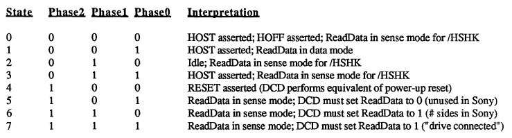
The DCD docs describe a state-based protocol that’s mercifully straightforward, compared to the oddities of the floppy drive interface. The Phase0, Phase1, and Phase2 lines on the floppy connector (sometimes called CA0, CA1, CA2) are used as a 3-bit state ID, to control the workings of a state machine governing Mac to DCD communications. At boot up, the Mac cycles through states 6, 7, and 5 in that order, checking the value on the ReadData line after each state transition. If it sees the values 1, 1, and 0, then it concludes that a DCD is connected to the floppy port, rather than a standard floppy drive.
HD20 communication is always a two-way exchange, with a command from the Mac followed by a response from the drive. From state 2 (idle), the Mac transitions to state 3 to indicate it wants to send a command. Seeing this, the DCD pulls /HSHK (the ReadData line) low to indicate that it’s ready to receive the command. The Mac then transitions to state 1 and sends the command, after which it transitions to state 3 to signal that it’s done. The DCD then brings /HSHK high again to acknowledge the end of the transfer, after which the Mac transitions back to the idle state.
When the DCD is ready to send a reply, while in the idle state, it pulls /HSHK low to indicate that it wants to send. The Mac then switches to state 1, and the DCD sends the reply bytes. After the last byte, the DCD brings /HSHK high again, and the Mac transitions back to the idle state.
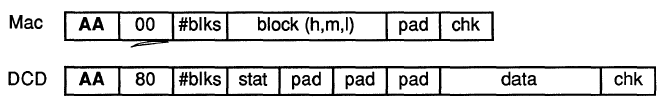
Commands follow a fairly simple structure. A read command and response are shown above. The command begins with $AA, which functions as a sync byte and start of command marker. The next byte is the command id. In this case, $00 means it’s a read command. Following that are the number of 512-byte blocks to read, a three byte block address, a padding byte, and a checksum.
The reply looks similar to the command. Again there’s an $AA sync byte, followed by the command id. The command id in the reply is always the command id from the request plus $80, though I’m not sure the reason for this. After that is the sequence number of the block being sent, a status byte (zero means OK), more padding, the actual block data, and a checksum.
The HD20 carries over the concept of tag bytes that originated with the Apple Lisa, and that are also present (but unused) on Macintosh floppies. Each block has 20 tag bytes, so from a low-level point of view, blocks are essentially 532 bytes instead of 512, and 532 bytes of data will be returned in reply to a read request. The Mac throws away the 20 tag bytes, however, and only the last 512 bytes are treated as disk data. From the point of view of an emulator, only those 512 bytes need to be filled from a disk image file, and 20 bytes of zeroes can be prepended for the tags.
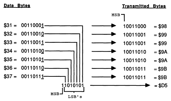
Because of the way the IWM works, the MSB of every transmitted byte must always be 1, so in effect there are only seven usable bits per transmitted byte. The DCD standard uses a 7-to-8 technique in which data is collected into groups of seven bytes, and then repackaged and transmitted as eight bytes with an MSB of 1 for every byte. This technique right shifts each of the seven bytes by one bit, chopping off the LSB, and setting the MSB to one. Then all of the chopped off LSBs are collected into an 8th byte. At the other end of the line, the receiver applies the reverse process to recover the original seven data bytes.
From Theory to Practice
That’s how it’s supposed to work, anyway, but there are many gaps and inconsistencies in the documents. One of the biggest concerns is that the March version of the doc differs in major ways from the May version. For example, the handshaking method described in the March doc is completely different than what I described in the previous section, based on the May doc. If there was that much change in the space of two months, it’s likely that the spec continued to evolve after that, and the May doc may not reflect the final version as it was eventually implemented.
Some important details just aren’t mentioned at all. What’s the checksum algorithm used? Nobody knows. An appendix also mentions a couple of dozen diagnostic commands, without describing what the parameters mean, or how the DCD should reply. Answering these kinds of questions requires a combination of educated guesswork, experimentation, and good old reverse engineering.
The code used by the Mac to communicate with the HD20 is contained in the ROM of the Mac Plus and other early Macs. Unfortunately this is raw 68000 machine language, so it’s difficult to read and understand what it’s doing. With the help of disassembler tools, the ROM data can be converted into 68000 assembly mnemonics, and symbolic names can be substituted for some known memory addresses, resulting in a code listing like this one:
L4772: MoveQ.L $4, D0
L4773: DBF D0, L4773
       Move.L D6, D0
       Add.L $810081, D0
       Move.B $-56, $400(A0)
L4774: Tst.B (A3)
       BPL L4774
       Move.B D0, (A0)
       Swap D0
L4775: Tst.B (A3)
       BPL L4775
       Move.B D0, (A0)
That’s not very instructive. But after long hours of studying and examining other nearby sections of code, some sense of structure does slowly emerge. For example, from looking at where A3 is set previously, I can tell that those Tst.B (A3) instructions are checking to see if the IWM is busy. And the Move.B D0, (A0) instructions are each writing a new byte to the IWM. Other clues are provided by the literal value $-56 appearing in the code, which when expressed as an unsigned byte is $AA – the sync byte. So what we have here is something that does a short busy loop, then adds $810081 to an unknown value from D6, and stores the 32 bit result in D0. Then it writes the $AA sync byte, waits for the IWM, writes the low byte of D0, waits for the IWM, and writes the high byte of D0. So it looks like it’s the preamble to sending a command to the DCD.
This is the kind of “deep in the weeds” analysis that’s needed to fill in the blanks for an emulation project. It’s something I’ve spent a lot of time doing for Floppy Emu and for Plus Too before that, so I’ve gotten pretty good at it, but I can’t really say it’s fun.
And a Progress Report
Armed with all this information, I began by hacking up the firmware on a Floppy Emu to identify itself as a DCD, and observe the proper handshaking rules for the various states. No data was actually sent or received. That was enough to get a noticeable reaction from the Mac: at bootup it froze for a long time, then when it finally did boot (from a SCSI drive), it complained that an attached disk was uninitialized and needed to be formatted. Then I wrote a simple test program to read arbitrary blocks from the DCD. The program always reported error -17 (driver can’t respond to this call). That was logical, but a little disappointing, as I could see from the ROM disassembly that there were many other more specific error codes that might be returned to give better feedback on what was and wasn’t working. I was hoping I might get an error like 64, no response received, or 33, timeout waiting for sync byte.
I spent a while tinkering with things, trying to get a more specific error than -17, but without success. I also tried using MacsBug to debug the HD20 driver routines while they were executing, but that appeared to create some new timing-related problems that messed things up even worse. Finally I decided to change course, and attack the other end of the problem by looking at what was happening on the Floppy Emu when the error -17 occurred.
I started with just displaying the current state number on the Floppy Emu LCD. I could see it go through states 6, 7, and 5 at bootup, just as the docs say it should. Then it went through states 2, 3, 1, 3, and 2, which looked like an attempted Mac to DCD command transmission. That seemed promising, so I leveraged the existing write code for Floppy Emu to try to collect the data bytes sent by the Mac, and display them on the LCD. That’s when I got the first payoff, as the received bytes were:
AA 81 B1 C1 81 80 80 80 80 80 FE
There was the $AA sync byte. And if you looked at the last eight bytes (beginning with $C1), it looked like a valid 7-to-8 encoding. Decoding those bytes yielded:
03 00 00 00 00 00 FD
That was command id 3 (drive status, according to the doc), with a bunch of padding and a checksum of FD. The sum of all the bytes mod 256 was 00, so that’s likely the checksum algorithm.
But wait, what were the second and third bytes for, 81 B1? Those shouldn’t have been there, according to the doc. Help! Truthfully I’m still not sure what those are, but after long examination of the ROM routines, I’m about 90% sure the first byte is the size of the data being sent, and the second byte is the size of the expected reply. Both sizes are expressed as a number of 7 byte groupings, then added to $81. In fact, the code that outputs those two bytes is the snippet I analyzed in the previous section.
So for the example above, the size of the data being sent was zero (no data payload for a drive status command), and the size of the expected reply was $30 groups of 7, or 336 bytes. Probably these size bytes were added to the DCD protocol late in the development process in an attempt to provide some amount of forward compatibility, so a device could gracefully handle an unknown command and send back a dummy reply of the correct size.
That’s where things stand today. With a little more experimentation, I’m hoping I can send back a valid drive status reply, or at least one that’s close enough to generate a more specific error code than -17. Then things will start to get very interesting.
Read 12 comments and join the conversation
Drag Soldering for Surface Mount Chips
I’ve seen many people look at surface mount chips, with their tiny sub-millimeter pin spacing, and assume it’s impossible to hand solder them without special tools and equipment. I used to believe it myself, but fortunately for us hobbyists, it’s actually quite easy to hand solder most SMT chips with nothing but a standard soldering iron!
The video above shows how I use the drag soldering technique to solder a 44-pin chip in a typical TQFP package. The chip is only about 1 square centimeter, so those pins are tiny. Attempting to solder them one at a time in through-hole style will never work. Instead, the trick is to use the magic of flux and the surface tension of solder to do the hard work for you. Once you get the hang of it, it’s as easy or easier than soldering a through-hole component.
The process begins by applying a liberal amount of flux to the pads, then positioning the chip on top. I use a pencil eraser to hold the chip steady while I tack down a couple of pins with a blob of solder from my iron. If some pins accidentally get bridged together while tacking them down, it’s OK. Next, I apply more flux to the sides of the chip, wetting both the pins and the pads underneath. The final step is to lay a few millimeters of solder onto the pins at the edge of a row, then use the iron to melt it and drag the molten solder blob horizontally across all the pins in the row. It seems as if that should bridge every single pin together into a giant mess, but with enough flux the solder will magically stick only to the pins and pads, without creating any bridges between them. It’s fun to watch!
Most of the time, I’m able to solder all 44 pins with this technique without creating any bridges. If I do create a bridge, I can often fix it by applying more flux and then briefly heating the bridged pins with the iron. The video shows how to recover when that trick doesn’t work: a piece of solder wick (a braid of thin copper wire) can be laid on top of the bridge, with the iron laid on top of the wick, and the excess solder will be sucked up into the wick and leave a clean joint behind.
Read 6 comments and join the conversationBoard Revision 1.2
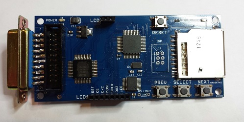
Introducing Floppy Emu version 1.2: it’s blue, because blue makes it go faster! Buy yours now from the Floppy Emu product page.
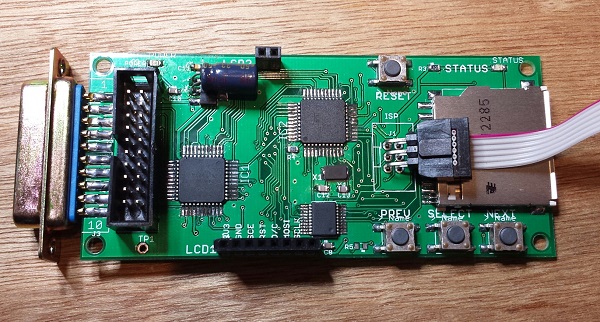
Version 1.2 is a minor update that cleans up a few details. You may have noticed that the silkscreen labels on the version 1.1 boards looked a bit strange, with some overlapping labels and most parts labeled twice. That will teach me to submit my designs to the PCB fab without inspecting the Gerbers first! Version 1.2 corrects this, and makes everything much more readable.
More significantly, the pin assignments on the LCD connector have changed. The leftmost pin was 3.3V in version 1.1, but now it’s RESET, and the other pins have changed as well. This was done to accommodate a change that’s occurred in Asia where these LCD panels are made. About six months ago, I noticed that two versions of this Nokia-clone LCD were available for sale online, seemingly identical except for the order of the pins. Over time, LCD panels with the old pin layout became harder and harder to find, so I’ve switched to the new pin layout beginning with version 1.2. I had to replace my stock of LCDs, and was left with a few old-style LCDs I can’t use, but that’s the price of progress!
Did I mention that it’s blue?
You’ll also notice a through-hole resistor footprint labeled LIGHT, adjacent to the PREV button. This was added to make it easier for people to mod their boards to enable the LCD backlight. I think the backlight looks like poop, so I don’t enable it for the Floppy Emus I build. Some people really, really want the backlight, though, and this was meant to give them a way to do it. Unfortunately, it doesn’t work. The new-style LCD modules surprised me by reversing the polarity of the backlight LEDs, so the circuit I designed doesn’t work. Doh! Eventually there will probably be a version 1.3 to correct it. The vertical spacing between the two LCD headers is also a bit off, so that’s another point to address in a future version. But other than those minor headaches, I’m quite happy with this new version 1.2.
Mounting holes were added to the corners of the board in version 1.1, with the idea of supporting a case for the Floppy Emu. But to my knowledge, no one has made one yet. It should be simple to cut and drill two pieces of acrylic to act as top and bottom plates, and put them together with standoffs like a sandwich. It wouldn’t be a true case due to the open sides, but it would still look pretty spiffy. More advanced makers might use the mounting holes to anchor a custom 3D-printed case. At least one person was working on a custom case that looks like a miniature external Apple drive, but never quite got it to work. If you’ve got a cool case design, post it in the comments!
Read 3 comments and join the conversation
International Shipping Meltdown
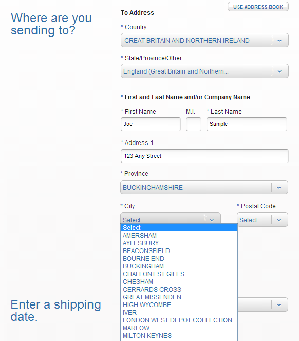
US Post Office, what are you doing to me? The USPS Click-n-Ship service has always been cumbersome, but it’s the only practical way to mail packages outside the USA via First Class Mail, which is the only way to send packages economically. Over the weekend the post office revamped the site, and now I’m unable to send any packages by First Class Mail. This leaves me with a choice between increasing my international shipping fee by 2x, or withholding all international shipping until some other solution is found. At the same time, the post office changed the method of address entry for most countries, so it’s no longer a free-form text entry, but a series of drop-down menus. If the city or postal code in your package’s address isn’t one of the choices provided, too bad.
In last month’s rant about international shipping headaches, I mentioned some of the problems I’ve encountered. Addresses must be formatted a particular way, regardless of whether that’s how they’re normally formatted in the destination country. Only numbers or the 26 letters from A to Z are permitted in the address. If the address is supposed to contain an accented letter, or any non-Roman letters like something from the Japanese or Korean alphabets, too bad. This is the US Postal Service. We don’t do accents.
The recent move to drop-down menus for composing the address makes matters even worse. Today I tried to send a package to the UK: destination Uxbridge, London, UB11 1BB. Look at the screenshot above, and you’ll see that I’m required to select a province before I can fill in the rest of the address. I wasn’t aware the UK even had the concept of provinces. So what province is London in? Ummm, England? Nope, that’s not a choice. Let’s see, British geography quiz, this should be fun. According to the post office, the city of London is in the province of… London! But then I had to choose a city (which should be obvious), given a list of 10 choices including “London”, “London West Depot Collection”, “Finchley Road”, and “Westminster”. Ugh. And no matter which one I chose, UB11 1BB was never offered as a choice for postal code. Total failure. I simply cannot mail a package to this address, using this service.
Then I discovered that the interface for choosing the shipping method has also changed. It used to be that you’d enter the package address, then on the next page you’d see a list of shipping methods including First Class, Priority Mail, and Priority Express. Now it’s a Javascript-enabled form that dynamically changes to show you the applicable shipping methods for the address as you type it. At least that’s the theory. In practice, it only ever shows Priority and Priority Express as choices. At first I thought this might reflect a change in policy for international shipping, but then I discovered that the same problem occurs when printing postage for domestic packages. RIP, First Class Mail?
I went to the local post office, waited in line, and spoke to an employee who assured me that First Class International was still a valid shipping method, and she was able to send the package to London UB11 1BB without problems. But it required almost an hour of my time, driving to the post office, waiting in line, and filling out custom declaration forms by hand, and it also cost 10% more than purchasing the same postage online by Click-n-Ship used to.
I’m not sure the best way to get this resolved. I tried Click-n-Ship’s live support feature, but got a generic error asking me to try again later. I spent an hour on hold waiting to talk to tech support before hanging up in frustration. Under the theory that maybe it was a browser bug, I tried Internet Explorer instead of my normal Chrome, but that didn’t help. Maybe there’s something about the address and package details I’ve entered that rules out First Class mail as a choice, so it’s never shown as an option? I don’t think so, though.
At this point, I think my only option is to hope that this is a bug and not a policy change, and hope that it magically gets fixed in the next few days. If not, I may have to start shipping international packages by Priority Mail, and charging substantially more for international shipping than I have been thus far. I sure wish the post office weren’t such an inscrutable bureaucracy, or that any of the other carriers like FedEx offered reasonably-priced options.
Edit: It looks like First Class International postage has been fixed! Thank you, USPS web programmers. My apologies to everyone who suffered through my rant. Now if I can only figure out how to ship to London UB11 1BB…
Edit 2: Choose “other” from the Province drop-down menu, then you can type in whatever you want without needing to follow the post office formatting.
Read 20 comments and join the conversation