

Electric Bow Tie
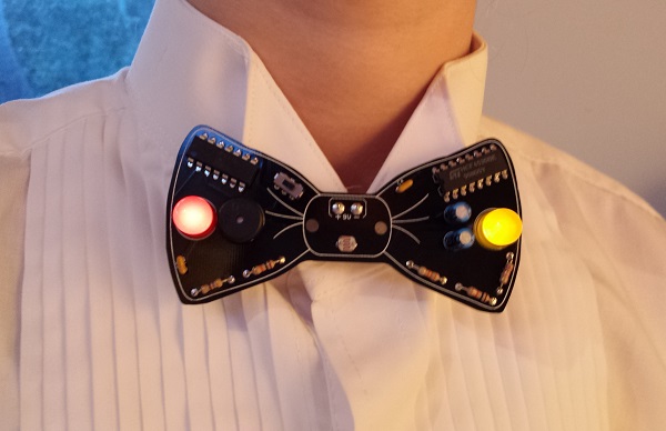
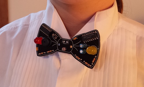
The Electric Bow Tie is an electronic kit with a circuit board shaped and sized like a real bow tie, and colored classic black. Once assembled, a piece of ribbon can be anchored through the board’s central mounting holes, making it easy to wear at the collar of a dress shirt or tied around a ponytail.
Attending a wedding soon? Graduation ceremony? Audience with the pope? The Electric Bow Tie is the perfect geek accessory for any formal occasion. Your audience will be blown away by your neck-based audio-visual spectacle. Imagine the scene as bow tie lights flash and a digital melody bursts forth. With a wave of your hand you exert theremin-like controls, shifting the pitch of digital warbling at will. Is this magic?!
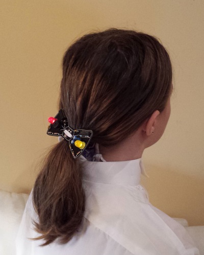
Ladies: are bow ties not your style? Turn it around, and make a dazzling electronic ponytail holder perfect for your next Maker Faire presentation or inaugural ball.
The kit contents are simple through-hole parts, so it’s easy to solder even for a beginner. Build one for yourself, or get a kit for your kid/student/friend and assemble it together. Who wants the boring LED blinker in a typical learn-to-solder kit, when you could have a crazy bleeping sonic bow tie theremin?
Sadly the Electric Bow Tie 3000 kit is no longer offered for sale, but you can make your own. Download the schematic, PCB files, parts list, and instructions here.
Instructions
- Electric Bow Tie 3000 Kit assembly instructions
Wear and Usage
To wear the Electric Bow Tie 3000 around your neck, drop the battery inside your front shirt collar and allow it to hang loose by the clip wires. Normally this is all that’s needed to anchor the bow tie at your collar. If desired, a ribbon or shoelace can be passed through the two holes in the center of the circuit board, and tied around your neck.
To wear the bow tie as a ponytail holder, pass a ribbon through the center holes, and tie it around your hair at the base of your skull. The battery can be dropped inside the rear of your shirt collar, or hidden inside your hair.
The pitch bends of the digital melody are controlled by the level of illumination on a photo-sensor mounted at the tie’s “knot”. The bow tie works best indoors, in a room with moderate lighting. To shift the melody’s pitch higher, move closer to a light source, or turn the bow tie to face directly towards the light. To shift the melody’s pitch lower, move away from the light source, or shade the photo-sensor with your hand. By waving your hand rapidly above the photo-sensor, a warbling vibrato effect can be achieved. Spooky!
How it Works
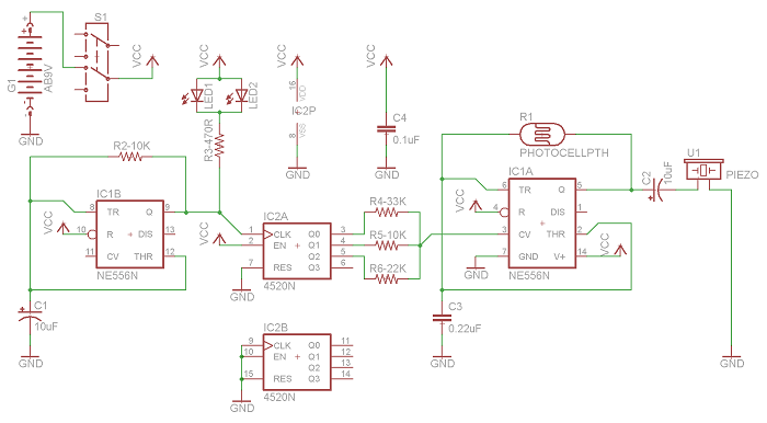
The fun begins with a classic 555 timer, configured in astable mode to generate a square wave with a frequency around 1000 Hz. This is IC1A as shown in the circuit diagram. The exact frequency of the square wave is determined by the values of C3 and R1. R1 is a photo-resistor whose resistance varies with illumination. This causes the timer frequency to shift up or down in response to changing light conditions. When connected to a speaker, it creates a continuous tone whose pitch changes depending on the light.
A continuous tone isn’t very interesting, but we’re not done yet. A second 555 timer is also configured in astable mode, generating a square wave at about 4 Hz (250 millisecond period). This is IC1B in the circuit diagram. A pair of LEDs are connected to this square wave output, causing them to blink 4 times per second.
The 4 Hz signal is also used as the clock input to IC2A, a 4-bit binary counter. The circuit uses a CMOS CD4520 binary counter chip, instead of a more common 7400 series binary counter, because the CD4520 can tolerate supply voltages up to 20 V. This makes it possible to run the entire circuit directly off a 9 V battery, with no voltage regulator.
The lowest three bits of the current count are connected through series and parallel resistors to the control voltage input of the first 555 timer. This biases the continuous tone up or down in pitch, with a new bias voltage appearing every 250 milliseconds when the counter advances. The result is a repeating melody of eight notes, whose relative pitches are set by the binary counter, and whose overall pitch can be shifted further up or down by changing illumination at the photo-resistor. Is it science, or sorcery?
5 comments5 Comments so far
Leave a reply. For customer support issues, please use the Customer Support link instead of writing comments.
Planing on picking one of these up next pay day. Also planing on seeing if i can wrap this in fabric but keep the photo-resistor able to see.
I’m sure you could – but you’d be hiding the best part of nerd pride! 🙂
Any of the parts except the two chips could also be soldered onto the back of the board, if you prefer to keep them hidden. Or put only the LEDs and photoresistor on the back, then flip the whole thing over so the “back” becomes the new front.
Proud owner 🙂
I wore one yesterday while at the Silicon Valley Electronics Flea Market – it got lots of compliments!
screeeeeeeech!
The least it could do is make modem and fax sounds.