

Video Palette Setup
I’ve been thinking some more about the best way to set up the palette for BMOW’s video system. It’s the only part of the design that I’m not really happy with. There are a number of different options I’m considering. Here’s a summary of each one, along with a sample palette image showing all the possible colors. I’ve tried to arrange the colors in each sample in the most pleasing way, but try not to let the ordering of the colors sway your opinion.
8-bit palette entries, RRRGGGBB format
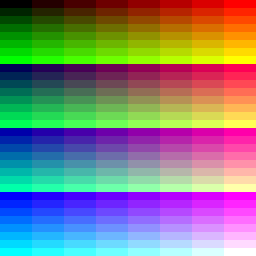
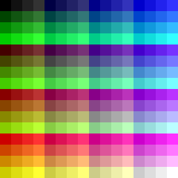
 This is the current plan. Two alternative orderings of the same 256 colors are shown here. Each entry is a single byte, with 3 bits of red, 3 bits of green, and 2 bits of blue. It’s simple to understand and build, and requires two 3-bit DACs (digital to analog converter) and one 2-bit DAC. There are 256 possible colors, and the division of bits between red, green, and blue is asymmetric. Only 8 or 4 intensities of any given hue are possible. For grayscale, it’s limited to either 4 shades of gray, or eight shades where some “grays” have too much or too little blue, since there’s less precision for blue than for red and green.
8-bit palette entries, HHHIIIII format
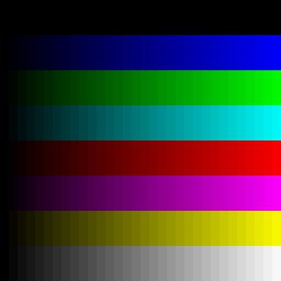 Each entry is a single byte, with three bits of hue and five bits of intensity. The three hue (H) bits are used to switch the R, G, and B color outputs on or off. Then for any color outputs that are on, the five intensity (I) bits define the intensity for all of them. There are still only 256 possible colors, but it’s symmetric in that all the color channels are treated identically, and it permits 32 intensities per hue. It requires a single 5-bit DAC whose output is used for all three color channels, and three transistors to switch the analog outputs on and off according to the H bits (I think this would work– I need to sketch up an appropriate analog circuit). The big drawback is that there are only 8 hues, so some colors like orange and brown can’t be rendered. Also, 39 of the 256 possible colors are black, which seems wasteful. That’s the entire top row and left column in the sample image.
8-bit palette entries, HHHHIIII format
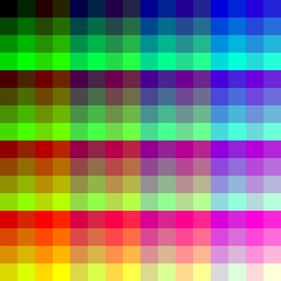
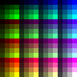
 In theory this would yield 16 hues, with 16 intensities per hue, which sounds like a decent compromise. In practice, I can’t think of a simple way to define 16 hues from the four H bits. Three bits of H are easy to treat as on/off controls for the R, G, and B channels, but four bits? If anyone can think of an obvious way to map eight bits of HHHHIIII to individual R, G, B outputs, I’d love to hear it. The image shows one possible mapping, but it’s a big switch statement in the program I wrote to generate the sample images, and I’m not sure how I’d implement it efficiently in hardware. Certainly some extra chips would be needed in the output logic.
8-bit palette entries, RRGGBBSS format
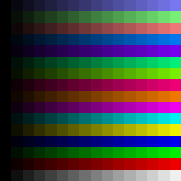
 Each entry is one byte, with four bits each for R, G, and B. However, the least-significant two bits for each color are shared among all the colors. There are 256 possible colors in total. They consist of 64 basic hues, and each hue can be biased brighter by 4 intensity levels, with the total intensity bias being as much as one-quarter of the total black-to-white intensity range. It requires four 4-bit DACs, but no other special output logic.
8-bit palette entries, RRGGBBII format
 This is very similar to RRGGBBSS format, except that the extra two bits are used to set the overall intensity of the pixel, rather than as the least significant bits of the color data. Each of the 64 primary hues can be rendered at 25%, 50%, 75%, or 100% of normal intensity. It’s a similar idea to the extra half-brite mode from the Amiga. The advantage over RRGGBBSS format is that there’s more fidelity among the darker colors. There is some redundancy in the palette, however: red = 01 (binary) with 100% intensity is the same as red = 10 (binary) with 50% intensity. I’m not sure what the best way to implement this in hardware would be. Possibly as a 2-bit intensity DAC, whose output is used as the reference voltage for three more 2-bit color DACs.
15-bit palette entries, RRRRRGGGGGBBBBB format
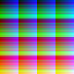 Each entry is two bytes, with five bits each for R, G, and B. There are 32768 possible colors. It requires three 5-bit DACs. Since palette entries are twice as large as the 8-bit formats, it also requires two palette RAMs arranged in parallel. Storing the data in a single RAM that’s twice as big won’t work, because all 15 bits for the pixel need to be output simultaneously. It also requires two output registers to latch the output of the palette RAM, instead of one. Overall this would provide the best-looking results, but require the most hardware, and double the amount of palette data that the CPU needs to generate.
16 Comments so far
Leave a reply. For customer support issues, please use the Customer Support link instead of writing comments.
Good news: I was able to find that UM70C171 VGA palette chip that John Honniball wrote about. I visited a store called Weird Stuff here in Silicon Valley, which has a whole warehouse full of electronics junk. I dug through eight boxes of old video cards, and found one with the coveted UM70C171, socketed. I also found a second card with the pin-compatible IMS G171, although that’s soldered in and not socketed. Then I found a third card with a socketed Music TR9C1710-66PCA, which I’m guessing is another pin-compatible clone, judging by the card, chip, and part number. Anyone ever heard of Music Semiconductor? I wasn’t able to find a datasheet, or confirm that it’s a compatible chip.
One odd thing is that only one of the hundred or so cards I looked at had a 25.175MHz oscillator on it, which is the horizontal frequency needed for 640×480 VGA. I was looking for one I could desolder and re-use. All the cards had oscillators at speeds like 36MHz, 40MHz, and 42MHz. I don’t understand how they could generate the necessary 25.175MHz clock from a 36, 40, or 42MHz base frequency.
So now I need to decide whether I’ll go with my existing design, or alter it to use the UM70C171. The existing design is more complex, requires more parts, and will have poorer color resolution. But on the other hand, I designed it myself, and it uses nothing but a couple of GALs, RAM, ROM, and some 7400-series logic gates. I guess I’ll finish up the details of the current design, see how complicated it becomes, and make sure I have enough board space before I decide for sure, but I’m leaning towards keeping the existing design and saving the UM70C171 for a future project.
Superb! Glad to hear that you found a palette chip, and a real G171, too! Some people at INMOS called them the Colour Look-Up Table chip, or CLUT. I’ve found my INMOS data books for the graphics chip sets, so if you need a scan of the data sheet, do let me know. You may need to supply a constant current to the DACs on the chip, and some VGA cards used a little 3-pin constant-current diode part for that, usually located right next to the CLUT.
Wow! Eight boxes of VGA cards in Weird Stuff — I wish I could take a trip there myself…
I found the datasheet online for the UM70C171, and I’ll probably use that if I use any of them, since it’s socketed and the G171 would need to be desoldered. There are some sample circuit designers for the current source, but I didn’t look at them much.
Weird Stuff is a great place– I can’t believe I’d never been there before, after living in the area for 12 years. Some of their stuff is listed online at http://www.weirdstuff.com , and there’s a shot of their “As-Is Warehouse” at http://www.weirdstuff.com/sunnyvale/html/as-is.htm . It seems like three decades of surplus/liquidation junk from every Silicon Valley company that’s ever gone out of business. It was strange to see top-of-the-line computers and peripherals that certainly cost thousands of dollars in the 1980’s, sitting piled haphazardly in cardboard boxes, for three dollars apiece or so. Need an old X terminal, Sun SCSI card, SGI Indy, Apple II floppy drive, voltage transformer, or oscilloscope? They’ve got them all.
One other question John: do you know if the part number suffixes like UM70C171-66 refer to the clock period in nanoseconds, or clock speed in MHz? I wasn’t able to find that in the datasheet. I’m guessing it must be MHz, since a 66ns clock period would be too slow for 640×480 video if my math is correct.
**Sigh!!**
I have so far bought one thing from that excellent firm, from their website.
What I do want to buy, however is only available via their storefront and I happen to be here in NYC, 3 thousand miles away from them. (It’s their collection of PDAs. I need to track down a cluster of the entire 3COM branded line of Palm devices, and then the regular line of Palm devices.)
I have a note into them about an idea. More later on that.
Yes, the suffix is the pixel clock speed in MHz. It’s mentioned at the very end of the INMOS data sheet, under “ordering information”. The older INMOS parts were either 35MHz or 50MHz.
As for Weird Stuff, well I already have two SGI Indys and there are a few Apple ][s in the loft… BTW, the Indy uses the Brooktree RAMDAC, a competitor of INMOS’.
Haha, after all the time I spent musing about these different RGB palette systems and constructing the sample images, I discovered a nice article on Wikipedia that covers the same topic, with nicer sample images: http://en.wikipedia.org/wiki/List_of_monochrome_and_RGB_palettes#Non-regular_RGB_palettes
I found an online store selling the UM70C171 chip. http://www.acpsurplus.com/servlet/StoreFront
They also have an ebay store, which is how I found it – searched for the chip in the ebay search bar. They have a bunch of other vintage chips too.
Does anyone know if I can use this chip with 12-bit wide RGB output? Or do I need a chip designed for 12-bit color?
It’s a 256 entry color palette, where each palette entry is specified using an 18-bit RGB value. The output is three VGA analog voltages for R, G, and B.
OK, I was wondering whether it would work with 12-bit colour information though. I guess I would have to do some binary maths to convert 12-bit output to 18-bit. I’m not sure what the output would look like.
Here’s the datasheet– hopefully this answers your questions. http://www.datasheetcatalog.org/datasheet/UMC/mXyztwts.pdf
I just ran across the discussion of the Inmos and Music Semiconductor Color Palette chips, one a few years late. I worked for both companies, as the responsible Applications Engineer for Inmos when IBM designed it into the original VGA cards, and I did the same for Music, along with working on the deign team. If your still interested, please add a comment here and I can answer most questions.
Hi Randy! Sounds like a fun part to work on. I did eventually get the UM70C171 working in my homebrew computer – read the later posts here for more details on the development of the video system.
I know this is 8 years old but I have to say, the ‘RRGGBBSS’ palette is a really neat way of using 8 bits to get such a wide range of colors and still have 16 true grayscale colors. It does make it impossible to achieve full saturation and full brightness at the same time, but this is probably very rarely a problem for someone using such a small palette. I will probably be using this idea for a LED display, where such issues will be basically invisible. Thank you.
Compared to websafe, RRGGBBSS has better brightness precision, but worse hue and saturation precision. Both are subsets of 12-bit RGB. There are many ideas for bitwise 256 color palettes, like subsets of 9-bit RGB; for example reducing the 8 LSB combinations to 4 with xor for a sphere–packed palette but no white, or sharing the red and blue LSBs. I suppose trying to do a subset of 15-bit RGB will lead to even more hue sacrifice, that it’s better to use websafe or something rounded to 1÷31 and add the grays.
The same comparison comment (better brightness precision, but worse hue and saturation precision) can be said about many palettes compared to RRGGBBSS. RRGGBBSS has only the color precision of 6–bit RGB, but a brightness precision of 12–bit RGB. 8×8×4 RGB uses the two extra bits for more color precision instead of more brightness precision; it has 1÷7 red, 1÷7 green and 1÷7 yellow, but no 1÷7 gray. Color precision does help, brightness precision depends; it might be not very useful, or it might be very useful (anti–aliasing, gradients). I personally like RRGGGBBV (V is violet, the shared LSB of red and blue), as it offers 8 grays, but still offers superior color precision to 6–bit RGB, and is bitwise unlike websafe.