

Z-80 Based Credit Card Terminal
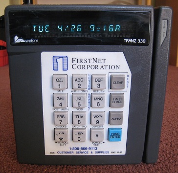 I found an old credit card terminal at an electronics surplus store recently, and bought it to tinker with. $5 at Weird Stuff in Sunnyvale! This Verifone Tranz 330 was used to process credit card transactions in the 80’s and 90’s, and is probably still used today some places. I wasn’t really interested in the credit card aspect though, but hoped to take it apart, learn how it works, and see if I could do anything interesting with it. Inside is a simple, self-contained 8-bit computer with a lot of hacking potential.
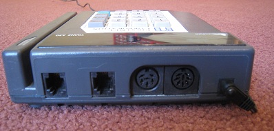
The Tranz 330 has a 16 key keypad, 16 character vacuum flourescent display (each charachter with 16 alpha-numeric segments), and a serial port with an 8 pin DIN connector. It also has an internal modem, a pair of telephone jacks, and a specialized 6 pin DIN serial port intended for use with peripherals. Lots of interesting interfaces to experiment with here.
Inside are two stacked circuit boards. The logic board contains a Z-80 CPU running at 4MHz, with a 32K socketed ROM, and 32K SRAM. The display board contains the VFD controller and keypad interface, as well as a piezo speaker.
So what do I do with this thing? It’s a full-on Z-80 based computer capable of lots of mischief, cramped only by the limited keypad and display. In theory, I could play Zork on this box. The socketed ROM would make it easy to replace the credit card terminal program with something of my own.
The challenge lies in determining the memory and I/O mapping used. How do you read the keypad? How do you write a character to the display? How do you work with the serial port or drive the speaker? I could dump the contents of the ROM and reverse-engineer the credit card program to find the answers. That’s probably the best way to go, but it sounds like a pain in the butt. I could also attach probes and examine the busses with my logic analyzer while the terminal is running. The logic and display boards are joined by a single 20 pin connector, so there’s not that much to analyze.
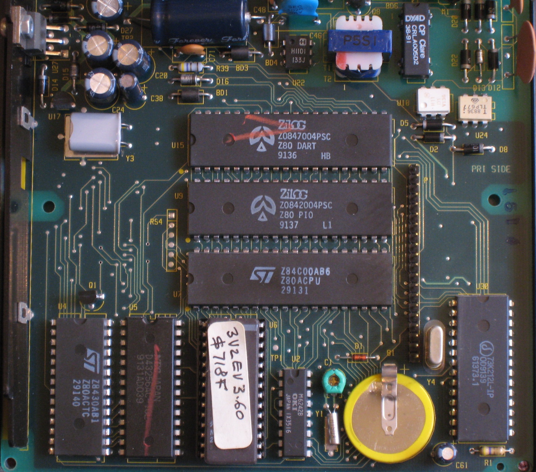
Meanwhile, let’s take a closer look at the components on the circuit boards, and see what’s there. Examining the CPU board first, in the center there’s the Z-80 CPU, PIO (parallel ports, probably used for the keypad and display), and dual UART (presumably used for the serial ports). Across the bottom row from left to right, there’s the Z-80 counter/timer, 32K SRAM, 32K EPROM, real-time clock chip, battery, and the single-chip modem. There are a few smaller chips at the top– I couldn’t learn anything about them, but by their placement I’m guessing they’re related to the phone interface.
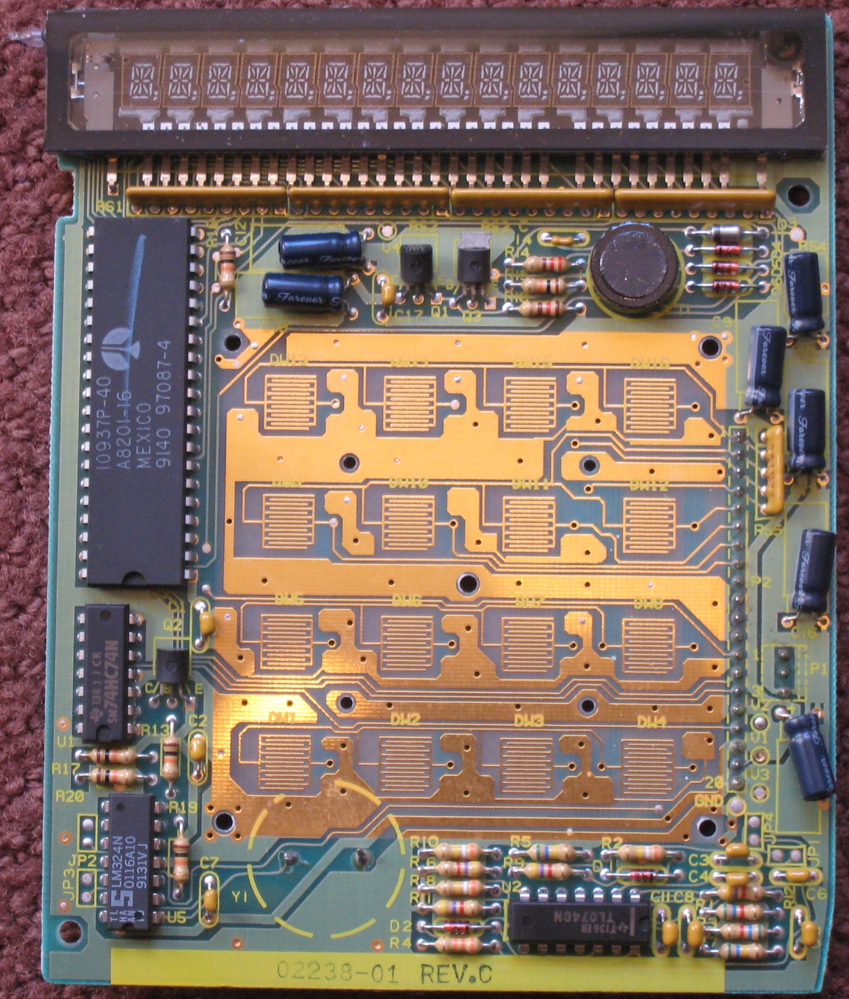
On the display board, examine the chips going counter-clockwise beginning with the largest chip. The large chip is the VFD display controller, a Micrel MIC10937. Following that is a dual-D flip-flop chip, a quad op-amp chip, and a second quad op-amp chip of a different type. I’m not sure what the eight op-amps are needed for– powering the VFD perhaps? Driving the speaker? Decoding the keypad key presses?
Post your best ideas for interesting hacks using this little box!
Read 33 comments and join the conversation33 Comments so far
Leave a reply. For customer support issues, please use the Customer Support link instead of writing comments.
The memory map most likely has the ROM as the low 32K and the RAM as the high 32K. This would make for easy decoding that could be done with a single transistor, like Q1.
To work out the I/O map I’d dump the ROM and look for the I/O routines. As the Z80 has a separate I/O address space this should be fairly easy.
The small chips at the top are optoisolators and part of the phone line interface.
Lee.
You’re right about the RAM and ROM in the memory map. I’d forgotten that the Z-80 also has a separate I/O address space, so I need to figure out which I/O ports are mapped to all those devices, and even more importantly, what values to output in what order to control the devices. Against my better judgement, I dumped the contents of the Tranz ROM, ran it through a Z-80 disassembler, and have made some progress reverse-engineering it to help answer those questions.
If you hooked the modem output up to an audio output (maybe even the piezo speaker) you could turn it into a funky DTMF drum machine + white noise generator.
BTW – did you see the “Tranz 330 Reference guide” at the bottom of http://www.verifone.com/technical-support.aspx ?
There is something in that described as a memory map, but it is not what you may be hoping for. On the other hand, it looks like it would give you enough info on how to write your own application in ‘Terminal Control Language’, assuming that is what is in ROM
Given the lack of logic chips on the board I would also guess that each I/O device is addressed by tying its enable line to an address line. It may be worth at least buzzing out A7 and below to the the enable pins on the CTC (16), PIO (4) and DART (35).
The opamps are probably part of the magstripe reader circuit.
The “Tranz 330 Reference guide” on the page that Jonno linked gives the pinout of the ports in appendix B.
Lee.
I like the idea of a self-contained music machine! The rudimentary speaker control may not be up it, but I’ll try!
Yup, I’ve read the Tranz 330 reference manual, and while there are a few good tidbits like the serial port pinout, it mostly describes how to write custom processing apps in a custom language running inside their “credit card OS” – what I call the program in the ROM. My hope is to replace the ROM altogether, and write something interesting in native Z-80 assembly.
Through a combination of tracing out the connections on the boards, and examining the disassembled ROM, I’ve made some pretty good progress towards figuring out how things work and where the devices are mapped. There is a hidden LS138 and HC10 on the reverse side of the CPU board used for address decoding.
I feel like I’m pretty close to being able to work with the keypad, display, and speaker now, and it’s more a question of reading the appropriate data sheets and learning more Z-80 assembly than in reversing the Tranz hardware design. I’ll post an update once I have something working. It would be awesome if I could offer some documentation and simple library routines that let anyone run a general purpose Z-80 program on one of these boxes by replacing the ROM, since they’re so common and inexpensive.
Great work !
i am inspired to
make revese
a 10937 due its not aviable
at market and VFD alpanum not aviable too.
i have 10937 by MICREL , also i read
about OKI and ROCKWELL .
so i have a MICREL version.
Please give more information about
power supply 10937 ( pin 1 VSS pin 18 VDD and what is logic levels (voltages )on pin 20 power-on-reset ,21 DATA ,22 SCLK) , also about power supply of Z80PIO.
Best wishes , Pete !
I have a Verifone TRANZ 380X2, and I was wondering how I could hook it up to my IBM server running linux. Right now I have the first phone RJ11 jack connected to a serial/RJ11 converter which is connected to my serial port on the back of my server. I was wondering if I could communicate with this terminal somehow and how would I go about doing that? I also have an adapter that sticks in the original output and splits to PS2, I tried adding then another adapter from PS2 end to USB > USB male to USB male, but didn’t really try it. I just would like to use some type of software to reset this terminal and also see if the card strip is capable of writing to blank cards. Write me back please if you have any info that might help. I know little to nothing about TCL and or programming for the Z80…
Hi, would happen to know the configuration for the cable in order to do terminal to terminal downloads (master – slave) Din8 male to Din8 male.
Thanks in advance
Joe Riverside
Anybody out there??
I have 330’s, 530’s and 380×2’s… power packs, some cables, wall mount plates etc., some new in the box from Verifone.
I used to be a TCL application programer.
I would like to sell these units cheap, maybe just shipping rather than junking them.
Contact me at kenconner@clockmaster1.com
I want to hack one of these things, and use it as a Shop Clock-In and Clock-Out system. with ID cards. Now, I wonder if I can just replace the Z80 board with an AVR board that hooks back to my server. Problem is, the F2F stuff. Now I know they do make 3rd party F2F Decoder ICs. Does the magstripe reader put out clean F2F to be decoded by another IC?
I dont know how to write an F2F decoder for an AVR/Arduino. So not sure what to do about that.
You can buy new, stand-alone magnetic stripe readers for not much money if that’s your main focus. Probably easier than removing and replacing all the guts of a Tranz 330. But if you still want to go that route, I believe the Tranz 330 magstripe reader is simply hooked up to an interrupt pin on the Z-80. So in theory you could reconnect it to an AVR interrupt pin instead, and write new software to handle the data.
Yea, but thats no fun. I want the FUN route. haha. But since the trans330 has a display, and keypad, i figured it would be a good fit as I can use the keypad for punching in a PIN, or 1-clock in, 2-clock out, 3-lunch. etc…
Now, sure I could hook the unit up to an AVR with an interrupt, but how to decode? The only thought I came up with is use a 16-bit Timer, and on each pin-interrupt edge trigger, store the timer value and reset the timer. if the timer overflows, I either stopped the card, or finished the swipe.
Then I assume I use the first couple values as a reference with a +/- tolerance? Not sure…
well i have been goofing off with this for awhile now, and I cannot seem to decode the F2F using INT0 on an AVR, someone would have to write the ASM code to do that, so I ended up moving to a MagChip… Anyways, it appears the 380 is a different animal. it has a little microcontroller ASIC for the F2F on the top board, but no idea how to work it, has to be scoped. And, the display uses 5V at VSS instead of 0V on the trans330, so my AVR cant communicate with it, I think its polarity-inversed. display RESET is the same though.
Did you look at the card reader routines in http://www.bigmessowires.com/tranz330.asm.txt? They’re Z-80 assembly, but you should be able to understand it enough to use the same method for F2F decoding on an AVR. The transitions may even be slow enough that you could do it with software polling instead of timer interrupts.
Yes I have. but my ASM is weak. I know a little bit of AVR before I decided to switch to high level languages. I know virtually 0 Z80, I tried getting into Z80 years ago but it sorta went over my head. same deal with the 8051. I knew 6805 the best honestly.
I am more of a high level language person myself, BASIC/VB only though. C is out there with Z80 for me.
Oh, and I know JAVA, and PHP. I forgot about that. haha. Anyways, I did try using the 16-bit timer in a Mega32 to monitor the card line, and each INT0 would print the timer value to me, and reset the timer until the next transition.
Problem was, I couldnt make heads or tails of it. the timer values were all over the place, and not very consistent. Probably because of noise, and maybe even the acceleration of sliding the card changing certain degrees. So I couldnt really do anything from that angle, because my math skills just arnt that great to deal with the magnetic noise floor, etc…. Then it could also been my implementation as well. who knows? for my AVR compiler, I use BASCOM-AVR as thats what I have gotten advanced at.
I think I have the Z80 routines figured out for the most part. Except for this one thing:
card_scale_bit_duration:
its commented as doing A = 11/8 but I have no idea what that means, and what its actually doing. Can you elaborate with an example value? it would better help me understand whats going on there..
the card_read routine was pretty streight forward, its just taking a looping value B, and putting it into a buffer and incrementing it. like a big byte array. of just B values. Which is similar to what I was doing with the timer.
I didn’t actually write the card reader code. I dumped it from the original ROM, decompiled it, analyzed it, and wrote comments describing what it does, but I can’t necessarily explain WHY it does it. So that particular routine multiplies the bit time by 11/8, but I don’t know why. I think it’s related to the fact that all bit durations should be either N or 2N. So duration greater than 11/8N is used as the threshold for distinguishing between a 0 and a 1 bit.
My question was a bit more low-level than that.
11/8 what is an 11/8? to me that looks like an improper fraction. haha.
I guess what I mean is, if I were to pull up windows calculator, do I do 11 divide 8? thats where I am confused… I am trying to work out the math high-level using a regular calculator. But I dont know what that math is…
Yes, 11 divided by 8, which is 1.375. I’m not sure why it used that instead of 1.5 as the threshold between 1 and 2.
BTW, the Tranz 380 has a microcontroller on the top PCB that intercepts the F2F information from the head, and it doesnt work like the 330 at all, it doesnt produce any pulses. just a single low, then high.
So I gotta probe that one out, because I have a bunch of the 380s as well.
Hi! I’m surprised and elated to stumble across this page. I was employee #2 with Verifone, and I was on the design team for the Zon, Zon Jr, and most of the Tranz terminals.
The card reader in the 380 is indeed a reader chip, for the Jr and lower end Tranz we just used the interrupts and timing between them to read.
I don’t have much of the info anymore, but I’ll help where I can.
Hi David! If you haven’t already, check out my two follow-up posts on hacking the Tranz 330:
https://www.bigmessowires.com/2011/05/06/mozarts-credit-card/
https://www.bigmessowires.com/2011/05/10/mapping-the-tranz-330/
David: Awesome! Maybe I can pick your brain. How do you interface with the reader chip on the 380?
I don\’t know, the 380 was after my time. Hopefully there\’s a data sheet available?
Trivia: The first TCL program delivered to a customer was \”MNL\” read the Magcard, priNt it, and link back and do it again.
The Zon terminal (large, with phone on the back) has a complex sound generator chip, which we never really exploited.
Wow, I only just found this and as another former VeriFoner probably a few years after David, I can’t believe the amount of work that you guys have put into reverse engineering our equipment. As far as the sound goes, all it can really do is a square wave, which sounds really rough. On one of our later product lines based on the same hardware, we could network up to 32 units, if I recall correctly. I wrote a demo app that could play music on all of them at once, with harmonies naturally. Since a square wave sounds a bit like bagpipes, I had them play Scotland The Brave. Good times.
Haha. @Grant. I did something similar with this, I replaced the mainboard with an AVR Atmega and Ethernet shield so I could use the original VFD display, keypad, and mag reader, but the board designed differently so I could interface it with PHP Timeclock. That was fun.
I did find a much newer unit, with the LCD display, but that stuff was obfuscated and secure to the point you cant really do anything unless you know the underlying arch to the CPU (probably ARM). Hell even the LCD display was proprietary.
When we started designing these, we used 6 MHz Z-80 computers in S-100 frames as our “PCs”. The IBM PC was barely getting started, and was a weak competitor at that point. The terminals were 4 MHz Z-80 systems, so we were putting basically a version of a desktop computer to work as a credit card terminal. Given that we had serial ports, I suppose it might have been possible to run CP/M on them if we were inclined to do so.
In about 89 or 90, the whole Z-80 system was available at 20 MHZ(!) on a single chip from Hitachi, 100 pin QFP IIRC. Still, the Z-80 was relatively slow, and an 8 MHz AVR would have kicked it’s ass for sure. But that wouldn’t come along till much later. The Z-80 alternate register set was nice for handling interrupts without the usual push and pop dance, but of course well written code wouldn’t un-necessarily push or pop any registers anyway.
In the early ZON Jr and Tranz firmware Bob Loui put in a string “Nosey little fucker aren’t you” intended for those who would try to reverse engineer the rom. I believe there were also traps for disassemblers, since the Z-80 had multi-byte instructions (one reason it was so slow..) it was easy to mislead the disassembler by tossing in a few seemingly random bytes between routines.
Ha ha, that’s great. I don’t remember seeing any “nosy little fucker” messages when I was reversing the ROM, but maybe I had a different version. I actually just pulled up my commented disassembly of the ROM (https://www.bigmessowires.com/tranz330.zip) with everything that I learned or guessed while reverse-engineering it. I wrote the disassembly 9 years ago, and I was surprised that I barely remember any of it now. I’m impressed that the original engineers can recall these technical details on a 35-year-old project!
For the VeriFone folks, definitely check out these two posts if you haven’t already:
Reprogramming the Tranz 330 to play procedurally-generated music: https://www.bigmessowires.com/2011/05/06/mozarts-credit-card/
A reverse-engineering guide to the Tranz 330: https://www.bigmessowires.com/2011/05/10/mapping-the-tranz-330/
As to the AC adaptor: The ZON terminal needed multiple voltages, positive and negative. The Jr did as well, but we pulled this off a single AC winding. As the designs evolved, they may have gotten past the need for the negative voltages, but when you already have millions of AC adaptors in the field, and you’re getting them at a super cheap price, changing to a DC out version would only cost more money.
If you’re interested in the mostly non-tech side of these devices, I can HIGHLY recommend this book:
https://www.amazon.com/VeriFone-memories-first-ten-years/dp/B085K85MXW
Yours truly is pictured in a couple places as well. 🙂
EPROMS.. Ah the miseries…
Development involved each programmer having a burner and an eraser, and cycling those just about constantly. Major pain in the butt, and we wore out the EPROM sockets regularly.
One summer Dan Ryan and I spent in LA, changing EPROMS on some 2000 ZON terminals.
One is accessible through a hatch in the bottom, the other requires disassembly of the terminal. To make matters worse, we had an 8 chip gang programmer from some outfit that would typically yield only four or five usable chips, the other three were either unprogrammed, or damaged, and sometimes the ceramic package was split in half by the heat! We drove all over LA looking for anywhere that had those EPROMS, buying all they had on hand. We were working in the garage of one of our sales reps, and come to think of it, I don’t really remember where (if!) we were sleeping! Hour after hour, erasing, reprogramming and testing…. Fun days though.