

Building a Halloween LED Display
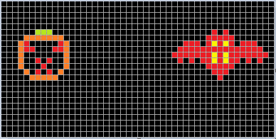
This Halloween, my daughter and I are working on a large LED display board for the yard. We started with a 3 x 6 foot pegboard with a grid of 24 x 48 holes pre-drilled, and 100 each red, orange, yellow, and green LEDs. 5mm size T 1 3/4 LEDs fit pretty nicely into the pegboard holes. Her job is to design some interesting animated shapes for the board, and my job is to figure out how to wire the whole thing up and power it.
My initial thought was to fill only the holes needed for a few specific Halloween shapes, and connect the LEDs using some ad-hoc point to point wiring. But the more I thought about measuring, cutting, stripping, and soldering hundreds of different ad-hoc wires, the more I hated the idea.
The Grid
Wiring up the board as a regular grid should be much easier, even if not all the grid points are used. The simplest method would be to lay down lengths of bare wire horizontally and vertically between the pegboard holes, using a plastic or rubber spacer at the crossing points to ensure the row and column wires don’t make electrical contact. To add a new LED to the grid, you’d just bend one leg down and solder it to the nearest row wire, and bend the other leg to the right and solder it to the nearest column wire. If the column wire was supplied a positive voltage while the row wire was grounded, then the LED at the intersection would illuminate. The great thing about this arrangement is that it wouldn’t require any wiring changes if you later need to change the shape of a jack-o-latern’s eye or a bat’s wing: you could just add a new LED to the grid, and alter the software that controls it.
Driving this grid would require 24 row lines and 48 column lines. The columns would be scanned rapidly one at a time, with all the row lines driven simultaneously to control the state of the LEDs in that column. If the columns were scanned rapidly enough, the human eye would perceive the whole display at once. The 24 row lines would most likely come from a shift register connected to the MCU, while the column lines would come from some type of decoder that enables exactly one of 2^N columns using N input bits from the MCU.
Splitting the Grid
Scanning through 48 columns one at a time would work, but with a 1/48 duty cycle, the LEDs would look very dim. A 1/8 or 1/4 duty cycle is more realistic in order to create an acceptably bright display. To achieve a 1/8 duty cycle, the grid would have to be divided into 6 independent sub-grids, each with 24 rows and 8 columns, with 192 LEDs per fully-populated sub-grid . Each of these sub-grids would require its own 24-bit shift register for the rows, and a 3:8 decoder for the columns.
Power requirements would likely force the sub-grids to be even smaller. Assuming 10 mA per LED, a fully-populated 24 x 8 sub-grid with all LEDs on would see 1.92 amps of current at the decoder, which is way too much for any common IC. After looking at some typical purpose-made LED driver chips, it looks like 300 mA is a more realistic upper limit.
I have a sample of the MAX7219 LED driver, which combines 8 row drivers and 8 column drivers with built-in column-scanning circuitry into a single chip. It can control 64 LEDs, with a total current limit of 320 mA. Each LED is driven with 40 mA when its column is enabled, and the 1/8 duty cycle results in an average drive current of 5 mA per LED. With 1152 total grid positions, it would require subdivision into 18 sub-grids to control the full grid with 18 MAX7219’s. For a brighter display, the MAX7219 could be configured with only 4 columns and a 1/4 duty cycle, for an average drive current of 10 mA per LED. That would require twice as many sub-grids and twice as many MAX7219’s.
Cost Estimate
At roughly $8 per MAX7219, the cost of driver chips would be $144 for the normal display, or $288 for the brighter display. That’s a bit out of the budget range for a weekend Halloween project! I suspect I could save a significant amount of money by using a simpler driver chip, but so far a specific solution has eluded me. The row drivers need constant current outputs, with a relatively high current limit in the 40 mA range. The column drivers (assuming they’re a separate chip and not combined like the MAX7219) need a very high current limit in the 300+ mA range.
The best option I’ve found for the row drivers is the STP08DP05B1, a $1.82 chip with eight constant-current outputs able to supply up to 100 mA per row and 800 mA total. I’m having a little trouble understanding the datasheet, though, and I’m not certain those are truly the per-pin current numbers, and whether they’re for sourcing or sinking current.
I’ve not yet found any good options for the column drivers, probably because I don’t know what such things would be called. High-power decoders? Analog demux switches? I need something with three digital inputs, that enables one of eight analog outputs, and can supply as much current as possible to that output, but at least 300 mA.
I could also use standard low-power shift registers and decoders, connected to separate high-power transistors. That would greatly increase the total number of components needed, though, since I’d need a separate transistor for every row and column in every sub-grid.
No matter what the eventual solution, it appears the cost for driver electronics will be at least $50 or so, and possibly much more.
Power
The power requirements of the full grid would be non-trivial. Assuming I used 18 of the MAX7219 drivers, the maximum current draw would be about 6 amps! That’s well outside the capability of any wall-wart 5V supply in my collection, and would probably require some type of bench supply or switching power supply scavenged from an old PC. However, the display would only draw 6A if it were fully populated with all LEDs simultaneously turned on. With a less than fully populated grid, and some upper limit on the fraction of LEDs that could be on at once, the power requirements might be reduced to a more reasonable level.
Solutions?
Since I’m not about to give up on this display entirely, nor wire up a few hunded LED’s with ad-hoc point to point wiring, some variation of the grid approach looks like the only viable solution. That means I’ll be spending a lot of money on driver electronics and a high-current power supply. To help keep the cost and assembly time down, I’ll probably only build a subsection of the entire 24 x 48 grid, but do it in a way such that the rest of the grid can be populated over the course of future holidays. 🙂
Edit: Thinking about this further, I’m starting to doubt whether this project is a very good idea. 5mm LEDs with a 1 inch grid spacing will do a very poor job of space filling, so this display likely won’t look very good. It will appear more like a bunch of isolated point lights than adjacent pixels in an image– OK for abstract displays, but not so good for making a recognizable image of a jack-o-lantern.
My bigger concern is safety. Combining a 6A power supply with a grid of bare wires on the back of the board sounds pretty dangerous. Curious fingers could get a significant shock.
Read 5 comments and join the conversation5 Comments so far
Leave a reply. For customer support issues, please use the Customer Support link instead of writing comments.
For the row drivers you can try the 74HC195. It can deliver up to 70mA (in total), but you might get away drawing a little more than that. A very cheap column driver can be made of an ULN2803 (8-channel high power Darlington array) in connection with a 8:3-mux or 74X195.
If you worry about the current sourcing capability of the 74HC195 you can add an UDN2981 or just use the TPIC6B595 (1.60 USD from Digi-Key).
To fix the problem of the LEDs being point sources, mount a sheet of translucent white or frosted plastic an inch or so in front of the LEDs to act as a diffuser. Don’t use LEDs with too narrow of a viewing angle.
Why not use an old AT/XT/ATX power supply, 5V and lots of Amps?
Why not backlight the whole board with a suitably powerful lamp and then cover the holes with coloured gel?
See this: http://www.youtube.com/watch?v=mGU8dlvOPUY
It is studends’ project called PIWO (BEER in Polish) which almost perfectly fits into English Powerfull Indexed Window O(=D)isplay.