

What Is The Bus Pirate?
I’ve been aware of the Bus Pirate for several years, but never had a clear understanding of precisely what it is, beyond being a serial adapter of some sort. Its name suggests a black-hat hacking tool, or maybe something for defeating DRM locks. The official home page only says “The Bus Pirate is an open source hacker multi-tool that talks to electronic stuff”, but that one sentence explanation doesn’t help very much. Links to the Bus Pirate Manual just show an advertisement, and the few “Bus Pirate for Dummies” style of guides I found weren’t super helpful either. I finally got curious enough that I decided to just buy one, and get the sense of the Bus Pirate through hands-on experimentation.
My conclusion is: it’s great! Imagine every hardware programmer, debugger, serial cable, and interface tool you’ve ever used, rolled into one. That’s the Bus Pirate. But it’s even better than that, because the Bus Pirate also offers interactive diagnostic features those other tools never dreamed of. If you like to tinker with digital electronics, the Bus Pirate is the tool you’ve always needed, without realizing how much you needed it. Here’s some of what it can do:
- program or read an AVR microcontroller (replaces the AVRISP mkII)
- program or query CPLDs, FPGAs, ARM micros, and other JTAG devices (replaces tools like Altera’s USB Blaster)
- connect to serial devices over a USB to serial connection (replaces the FTDI USB-to-serial cable)
- read or write Flash and EEPROM memory chips
- communicate with virtually any SPI- or I2C-based chip through an interactive command line console or a binary API
- passively sniff the SPI or I2C bus while other chips are using it, and record traffic
- other goodies like a low-speed logic analyzer and oscilloscope mode, raw digital (bitbang) mode, and more
To be fair, the Bus Pirate probably isn’t the best tool for any of these purposes – it won’t replace your high-end logic analyzer or expensive JTAG debugger – but it offers an amazing breadth of functions in a single device.
History
The Bus Pirate was originally developed in 2008 by Ian Lesnet for Hack a Day, and his post introducing the Bus Pirate remains the best overall summary of what it is and what it does. Ian later founded Dangerous Prototypes and took the Bus Pirate with him, releasing the design into the public domain, but continuing to improve the hardware and software with the help of others. Making it public helped build a robust community around the Bus Pirate, and today there are several companies selling variants of the Bus Pirate hardware, including Seeed Studios and Sparkfun.
Unfortunately, the public nature of the design has led to fracturing of the hardware, and some neglect of the software and documentation. For example, Dangerous Prototypes and Sparkfun use different naming conventions when describing versions of the hardware, leading to confusion when reading that a particular feature is available in version 3.5. And depending on whose Bus Pirate and cables you buy, the mapping of wire colors to signals may be backwards relative to other hardware versions. Be careful if you’re using somebody else’s color-coded wiring diagram! To confuse things further, there are also two major versions of the hardware in simultaneous development: 3.x and 4.x. The 4.x version is supposed to be the “new” Bus Pirate, but despite having been released in 2010 it’s still officially beta hardware, and new users are encouraged to buy the 3.x version. In practice, the community seems about evenly split between 3.x and 4.x hardware users.
The software and documentation suffer from not having a clear owner or maintainer. Those things take a lot of work, so it’s not surprising that a public domain project has some hiccups there, but it does make things difficult for a new Bus Pirate owner trying to get oriented. There are tons of Bus Pirate wiki pages on the Dangerous Prototypes web site, but many of them are out of date or inaccurate, or duplicates of other pages, or contradict other documentation on the site. The software harbors a few more potential points of confusion, with different sets of files contained in each firmware archive, and much ambiguity about which firmware is the right one to use.
But ultimately these are just minor bumps in the road. It may take a bit of extra reading and experimentation to get everything configured, but once the Bus Pirate is set up, it’s definitely worth the trip.
Hands On
I bought the Seeed Studio version of the Bus Pirate, hardware revision 3.x, along with the female-to-female jumper cable. Other people seem to prefer the cable with grabber probes. Consider what you’ll be connecting to most often, and buy accordingly. Or get both cables – they’re cheap. I also purchased the optional clear acrylic case. Shipping from Seeed took about two weeks to the United States.
Nokia 5110 LCD
After connecting the Bus Pirate to my PC, and installing the recommended terminal software (TerraTerm Pro), I connected to COM4 at 115200 bps and was on my way! The interactive terminal was a little daunting at first. The basic idea is to use simple text commands to choose an interface mode like SPI, I2C, or UART, configure the options for speed, pull-ups, and such, then type in data values to be sent to the device. Any incoming data from the device is displayed in the terminal window as well.
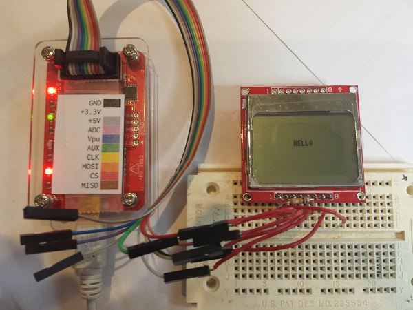
After plowing through a tutorial, my first test was interfacing with a Nokia 5110 graphical LCD. This 84 x 48 LCD has an SPI interface, and I’ve used it on several past projects. The Bus Pirate can optionally supply 3.3V or 5.0V to the connected device, so I turned on the power supplies and connected 3.3V to the LCD. The LCD’s SPI pins were connected to the corresponding pins on the Bus Pirate, and its D/C (data or command) pin was connected to the the Bus Pirate’s AUX pin. Finally, I tied the LCD’s reset pin to 3.3V.
From past experience with this LCD, I knew the magic series of command bytes necessary to initialize the display. In Bus Pirate terminal mode, they translated to:
a[0x21 0xBF 0x14 0x20 0x0c]
   a - set the AUX pin low (puts LCD in command mode)
   [ - asserts LCD chip select
   0xNN - data bytes to send
   ] - deasserts LCD chip select, ending the transfer
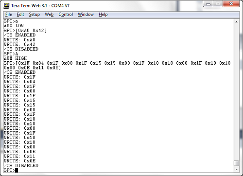
It worked! After a little more fiddling around, I was able to clear the display, set the cursor position, and print the “hello” message you see in the leader photo. In this case, my experimentation merely confirmed what I already knew about the LCD’s communication interface, but if I’d never used the LCD before, the Bus Pirate could have been a life-saver. Human-speed interactive communication with an unknown device like this is a much easier way of learning its behavior, compared to writing code for a microcontroller, or building a protoype PCB.
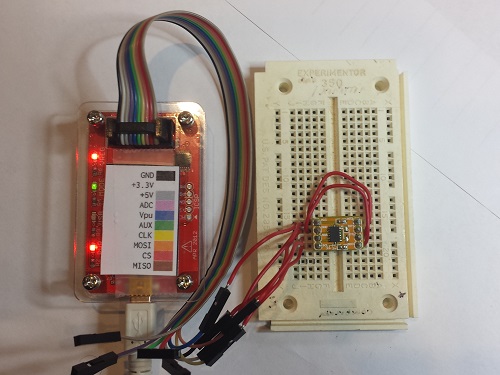
ADXL345 Accelerometer
My second test was an accelerometer module that I bought a few years ago, then put in a drawer and never used. Unlike the LCD, I had no prior experience with this chip. The ADXL345 can operate in either SPI or I2C mode, so for the sake of variety I chose I2C. Unlike SPI, I2C devices have a unique address used for bus communications, sort of like an Ethernet MAC address. Two addresses are needed: one for writing and one for reading. I could have read the datasheet to learn what addresses are used by the ADXL345, but I’ve got a Bus Pirate! So I connected up the pins, ran the Bus Pirate’s I2C address search macro, and voila! 0xA6 write address, 0xA7 read address.
OK, to go further I did need to peek at the datasheet. I learned that internal register 0 is the product ID register, and should return the value 0xE5. To read an I2C register using the interactive terminal, the syntax is not especially intuitive. To read the product ID register the command was:
[0xA6 0x00 [0xA7 r]
You’re probably thinking something’s wrong with those mismatched brackets, but it’s correct as written. [ sends an I2C start bit. 0xA6 0x00 identify the chip address and register number. [ sends another start bit, which is a restart, and is necessary for switching the chip from write to read mode. 0xA7 is the chip read address, and r reads a byte from register 0. Finally ] sends an I2C stop bit and ends the transfer. I ran the command, and saw happy 0xE5 come back as the read result.
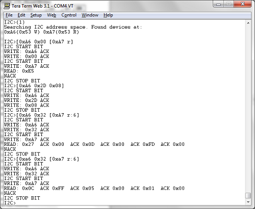
Reading the datasheet a bit further, I found that the accelerometer XYZ axis data is in registers 0x32 – 0x37. It’s two bytes per axis, with the low byte first. See the screenshot for the data from my test. The first time I queried the registers, the module was lying flat on my desk, with gravity nearly aligned with the chip’s Z axis. The measured axis values were 0x0027, 0x000D, 0x00FD. For the second test, I stood the module on its edge, with gravity nearly aligned with the chip’s X axis. This time the measured values were 0xFF0C, 0x0005, 0x0001. Pretty neat!
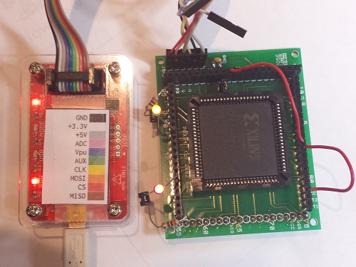
XC9572 CPLD
For my final test, I decided to try some JTAG programming. There are three different ways to use JTAG with the Bus Pirate, so it’s easy to get confused. The first method is from an interactive terminal session similar to the SPI and I2C examples. This isn’t very useful in practice, and support for it has been removed in recent firmwares, but it’s still mentioned in the documentation. The second method is to use the Bus Pirate as a JTAG dongle with OpenOCD software. I didn’t try this, but apparently recent versions of OpenOCD have Bus Pirate support built in, but it only works if you’re running the right firmware. I used the third method: using the Bus Pirate as a stand-alone XSVF player. XSVF files are a type of pre-recorded JTAG sequence, created by the Altera and Xilinx development tools for programming FPGAs and CPLDs.
Here’s where things get a bit complicated. My first two tests were interactive terminal sessions, running Terra Term on my PC with the default firmware 5.10 installed on the Bus Pirate. The XSVF player isn’t an interactive terminal mode, though, but a binary-only API requiring different firmware for the Bus Pirate. That meant I needed to learn how to update the Bus Pirate’s firmware and replace it with something different.
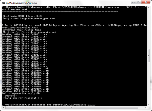
Poking around on the Dangerous Prototypes site, I found links to various firmware tools and downloads, but no indication of which one I should use. My Bus Pirate shipped with firmware 5.10, which seems to be the standard, even though it’s quite old and the latest firmware is 6.3. I eventually found what I was looking for, hidden inside the firmware 6.2 download archive: a firmware image named bpv3-xsvf-vb.hex, which provides the XSVF player functionality on the Bus Pirate. But how do you talk to the Bus Pirate when it’s in XSVF player mode, and send it the XSVF file you want to play? This requires a Windows program that’s inexplicably not included with the corresponding firmware, but must be downloaded separately. One I grabbed that as well, I was finally able to get started.
I’ve had an old XC9572 gathering dust in my parts box for years, and I’ve never actually used it, because I don’t own anything that can program it. Or I didn’t until now! I used the Xilinx ISE to create a simple design for the XC9572 – just a couple of AND and OR gates to prove that it worked. I then exported this as an XSVF file, connected the Bus Pirate, ran the XSVF player, and I was in business. It wasn’t fast, taking about 30 seconds for JTAG programming what must be the simplest part in Xilnx’s entire product lineup, but it worked. I hooked up some LEDs and jumper wires to exercise my AND and OR gates and make sure everything was working as expected. Hooray, new life breathed into this old CPLD!
Conclusion
The Bus Pirate is a remarkable tool. It’s a shame that the hardware, software, and docs have become somewhat muddied and difficult to follow, but it’s worth the effort to dig through and get it working. If you’ve got a box full of single-purpose programmer/adapter devices, then this is for you. I expect the Bus Pirate will occupy the top spot in my electronics toolbox for a long time to come.
Read 3 comments and join the conversation
3 Comments so far
Leave a reply. For customer support issues, please use the Customer Support link instead of writing comments.
Wow i literally just bought a bus pirate and the ADXL345 Accelerometer in order to learn how to use the bus pirate. I agree the documentation is not very new user friendly at all and needs to be updated.
This post is also a great help to me and learning to use teh bus pirate as well.
Thanks a lot.
Could you please demonstrate “classic” RS-232 communication sniffing (i.e. using Bus Pirate’s BUS sniffing mode to sniff “Hello world!” string, or is it available just for SPI/I2C ?).
Thanks !
I’ve never used it, but the “live UART monitor” is described here: http://dangerousprototypes.com/docs/UART#Live_UART_monitor You’ll need to know the baud rate and parity ahead of time, and it only monitors the RX pin, not the TX pin. That may be fine depending on your needs, but if you’re trying to observe communications in both directions between two other devices, the Bus Pirate will only sniff one side of that conversation.