

Missing Pull-up, Sad Trombone
Wah wah wah waaaaaaah. In the battle for 5.25 inch Apple II disk write emulation, it seems I declared victory too soon. While write support works great in many situations, it doesn’t work at all in others. The problem is with the /WRREQ signal from the Apple II, which goes low to indicate when a write is occurring. On old-school disk controller cards, like the Disk 5.25 Controller Card, or the even older Disk II Controller Card, this signal is generated by a 74LS05 hex inverter chip with open collector outputs. It can actively pull the signal low, but it needs an external pull-up resistor to pull the signal high. And Floppy Emu doesn’t have one. On the Apple IIgs (and probably also the IIc), the circuitry can actively drive /WRREQ high, so this isn’t a problem. And on other Apple II models, it’s also not a problem if there’s another real drive connected in the daisy chain, because that drive will have a pull-up, and /WRREQ is shared among all drives. But if Floppy Emu is the only disk drive connected to a Disk 5.25 or Disk II Controller Card, writes won’t work. Ouch.
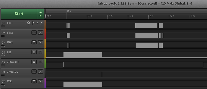
The logic analyzer trace above shows what happens. /WRREQ is connected directly to an input pin on the Xilinx XC9572XL CPLD. The input has a very weak pull-up that’s active at initialization time, as well as a keeper circuit that actively maintains the input at the last externally-driven level. At power-up, the weak pull-up pulls /WRREQ high, and the keeper circuit keeps it there. Then when a write occurs, the disk controller card actively drives /WRREQ low. At the end of the write operation it releases /WRREQ, but with nothing to pull it high again, the keeper circuit maintains the low value forever. To the Floppy Emu, it looks like a write operation that never ends. You can see the result in the trace. /WRREQ stays low forever, even after the drive enable signal is de-asserted.
Unfortunately, I don’t think there’s any way to fix this other than to add a pull-up resistor. The XC9572XL CPLD chip doesn’t have configurable built-in pull-ups that I can turn on in firmware, as far as I can tell. 5.25 inch read emulation will still work fine, as well as 5.25 write emulation on a IIgs or on any Apple II with another drive present. But for a single-drive Floppy Emu setup on an Apple IIe, write emulation won’t work without a hardware fix.
I already designed an adapter board, which I described in this earlier post. I had hoped that the adapter board would only be needed for certain situations of 3.5 inch Apple II disk emulation, but now it seems certain situations of 5.25 inch emulation will need it too. There’s too much “certain situations” about the whole thing for my comfort, and I’m sure it confuses everyone else just as much. So I’ll probably just rechristen the adapter board as a general purpose “Apple II adapter”, even though it’s not strictly needed for all circumstances of Apple II emulation. That will be easy to understand, and won’t steer anybody wrong. Power users can read the footnotes and discover which Apple II setups can work without the adapter board, if they wish.
Adding a pull-up resistor to the adapter board will be easy, but it does mean I’ll need to have new PCBs made. The only good thing in all of this is that it justifies my decision to postpone manufacturing large numbers of the adapter boards until after the Apple II 5.25 inch and Smartport disk emulation is working. If I had built lots of adapter boards three weeks ago when I thought they were only needed for 3.5 inch Apple II disks, I would now have a lot of angry people who’d bought them, and a pile of additional boards I couldn’t use.
Read 5 comments and join the conversation5 Comments so far
Leave a reply. For customer support issues, please use the Customer Support link instead of writing comments.
Would adding the pullup resistor to the adapter board affect 3.5″ drive mode operation in any way? I’d assume the added electronics in the IIgs (and IIc?) would take it into account. The 3.5″ daisy chain board appears to have some logic attached to the /WREQ line as well but the resistor in any connected 5.25″ drive appears to be in the circuit anyway as it directly passes the /WREQ to the daisy chain port.
It’s all good, and I’ve modified my prototype board to confirm it works. 3.5 inch mode emulation and IIgs/IIc support aren’t affected. The 10K ohm pull-up resistor is weak enough that it won’t interfere with an actively-driven high/low /WREQ signal from a IIgs, a 3.5 Drive’s daisy chain board, or other sources.
Hi Steve,
Would you consider releasing the details of the pull-up resistor modification for those of us who want to make the changes. I assume we can easily add a 10K resistor to the board to bring it up to the same revision as your revised board?
Cheers, Smartin..
Smartin – check out http://www.bigmessowires.com/2015/04/25/rom-03-revisited/
The pull-up modification isn’t one of the modifications shown in the “ROM 03 Revisited” post. The mods in the other post are required for 3.5 inch disk emulation on a IIGS ROM 03, and a few other scenarios. The pull-up modification is required for write emulation on 5.25 inch disks when using an old-style disk controller card like the Disk II Controller Card.
The pull-up is just a 10K resistor between /WRREQ and +5V. There are a few places where those signals can be tapped. I’ll post a photo later, or you can use the pin diagram from http://www.bigmessowires.com/2015/04/25/rom-03-revisited/ to see which pin is which on the disk connector.